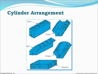
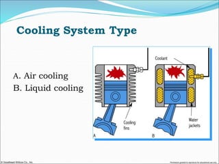
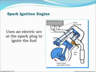
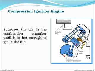
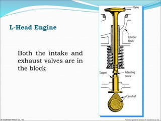
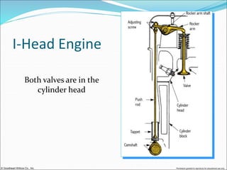
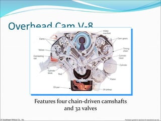
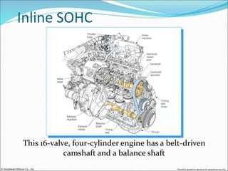
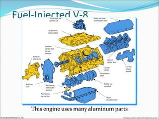
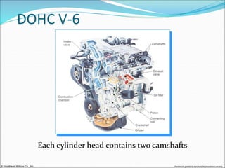
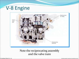
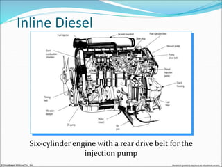
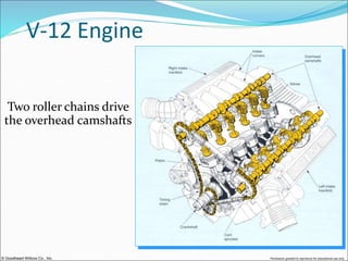
© Goodheart-Willcox Co., Inc. Permission granted to reproduce for educational use only
 Even though basic parts are the same, design
differences can change the way engines operate
and how they are repaired
 For this reason, you must be able to classify
engines
© Goodheart-Willcox Co., Inc. Permission granted to reproduce for educational use only
Common Engine Classifications
 Cylinder arrangement
 Number of cylinders
 Cooling system type
 Valve location
 Camshaft location
© Goodheart-Willcox Co., Inc. Permission granted to reproduce for educational use only
Common Engine
Classifications
 Combustion chamber design
 Type of fuel burned
 Type of ignition
 Number of strokes per cycle
 Number of valves per cylinder
 Type of aspiration
© Goodheart-Willcox Co., Inc. Permission granted to reproduce for educational use only
 Refers to the position of the cylinders in
relation to the crankshaft
 There are five basic cylinder arrangements:
 inline
 V-type
 slant
 W-type
 opposed
Cylinder Arrangement
© Goodheart-Willcox Co., Inc. Permission granted to reproduce for educational use only
Cylinder Arrangement
© Goodheart-Willcox Co., Inc. Permission granted to reproduce for educational use only
Number of Cylinders
 Most car and truck engines have either 4, 6, or 8
cylinders
 Some may have 3, 5, 10, 12, or 16 cylinders
 Engine power and smoothness are enhanced by
using more cylinders
© Goodheart-Willcox Co., Inc. Permission granted to reproduce for educational use only
Cylinder Numbering
 Engine manufacturers number each engine
cylinder to help technicians make repairs
 Service manual illustrations are usually
provided to show the number of each cylinder
 Cylinder numbers may be cast into the intake
manifold
© Goodheart-Willcox Co., Inc. Permission granted to reproduce for educational use only
Firing Order
 Refers to the sequence in which the cylinders fire
 Determined by the position of the crankshaft rod
journals in relation to each other
 May be cast into the intake manifold
 Service manual illustrations are usually provided to
show the firing order
© Goodheart-Willcox Co., Inc. Permission granted to reproduce for educational use only
Cylinder Numbering and Firing Order
© Goodheart-Willcox Co., Inc. Permission granted to reproduce for educational use only
Cooling System Type
There are two types of cooling systems:
 Liquid cooling system
 surrounds the cylinder with coolant
 coolant carries combustion heat out of
the cylinder head and engine block
 Air cooling system
 circulates air over cooling fins on the
cylinders
 air removes heat from the cylinders
© Goodheart-Willcox Co., Inc. Permission granted to reproduce for educational use only
Cooling System Type
A. Air cooling
B. Liquid cooling
© Goodheart-Willcox Co., Inc. Permission granted to reproduce for educational use only
Fuel Type
 Engines are classified by the type of fuel used
 Gasoline engines burn gasoline
 Diesel engines burn diesel fuel
 Liquefied petroleum gas (LPG), gasohol (10%
alcohol, 90% gasoline), and pure alcohol can also
be used to power an engine
© Goodheart-Willcox Co., Inc. Permission granted to reproduce for educational use only
Ignition Type
 Two basic methods are used to ignite the
fuel in an engine combustion chamber:
 spark ignition (spark plug)
 compression ignition (compressed air)
© Goodheart-Willcox Co., Inc. Permission granted to reproduce for educational use only
Spark Ignition Engine
Uses an electric arc
at the spark plug to
ignite the fuel
© Goodheart-Willcox Co., Inc. Permission granted to reproduce for educational use only
Compression Ignition Engine
Squeezes the air in the
combustion chamber
until it is hot enough to
ignite the fuel
© Goodheart-Willcox Co., Inc. Permission granted to reproduce for educational use only
Valve Location
 Engines are classified by the location of
the valves:
 L-head engine
 also called a flat head engine
 I-head engine
 also called an overhead valve (OHV)
engine
© Goodheart-Willcox Co., Inc. Permission granted to reproduce for educational use only
L-Head Engine
Both the intake and
exhaust valves are in
the block
© Goodheart-Willcox Co., Inc. Permission granted to reproduce for educational use only
I-Head Engine
Both valves are in the
cylinder head
© Goodheart-Willcox Co., Inc. Permission granted to reproduce for educational use only
Camshaft Location
 There are two basic locations for the engine
camshaft:
 Camshaft located in the block
 cam-in-block engine
 Camshaft located in the cylinder head
 overhead cam (OHC) engine
© Goodheart-Willcox Co., Inc. Permission granted to reproduce for educational use only
Cam-in-Block Engine
 Uses push rods to transfer motion to the
rocker arms and valves
 Also called an overhead valve (OHV) engine
© Goodheart-Willcox Co., Inc. Permission granted to reproduce for educational use only
Overhead Cam Engine
Camshaft is located in the
top of the cylinder head
© Goodheart-Willcox Co., Inc. Permission granted to reproduce for educational use only
Overhead Cam Engine
 OHC engines may use one or two camshafts per cylinder
head
 Single overhead cam (SOHC) engine
 uses only one camshaft per cylinder head
 Dual overhead cam (DOHC) engine
 uses two camshafts per cylinder head
 one cam operates the intake valves, while the other cam
operates the exhaust valves
© Goodheart-Willcox Co., Inc. Permission granted to reproduce for educational use only
Combustion Chamber Shape
 Four basic combustion chamber shapes are
used in most automotive engines:
 pancake
 wedge
 hemispherical
 pent-roof
© Goodheart-Willcox Co., Inc. Permission granted to reproduce for educational use only
Pancake Combustion Chamber
 Chamber forms a flat pocket over the piston head
 Valve heads are almost parallel to the top of the
piston
© Goodheart-Willcox Co., Inc. Permission granted to reproduce for educational use only
Wedge Combustion Chamber
 The valves are placed side-by-side
 The spark plug is located next to the valves
 When the piston reaches TDC, the squish area
formed on the thin side of the chamber squirts
the air-fuel mixture out into the main part of
the chamberthis improves air-fuel mixing at
low engine speeds
© Goodheart-Willcox Co., Inc. Permission granted to reproduce for educational use only
Wedge Combustion Chamber
Provides good air-fuel mixing at low engine speeds
© Goodheart-Willcox Co., Inc. Permission granted to reproduce for educational use only
Hemispherical Combustion Chamber
 Shaped like a dome
 The valves are canted on each side of the
combustion chamber
 The spark plug is located near the center
of the chamber, producing a very short
flame path for combustion
 The surface area is very small, reducing
heat loss
© Goodheart-Willcox Co., Inc. Permission granted to reproduce for educational use only
Hemispherical Combustion Chamber
First used in high-horsepower racing engines
Excellent design for high-rpm use
© Goodheart-Willcox Co., Inc. Permission granted to reproduce for educational use only
Pent-Roof Combustion Chamber
 Similar to a hemispherical chamber
 Has flat, angled surfaces rather than a
domed surface
 Improves volumetric efficiency and
reduces emissions
© Goodheart-Willcox Co., Inc. Permission granted to reproduce for educational use only
Pent-Roof Combustion Chamber
© Goodheart-Willcox Co., Inc. Permission granted to reproduce for educational use only
Other Combustion Chamber Types
 In addition to the four shapes just covered, there are
several less common combustion chamber
classifications
 Each type is designed to increase combustion
efficiency, gas mileage, and power while reducing
exhaust emissions
© Goodheart-Willcox Co., Inc. Permission granted to reproduce for educational use only
Swirl Combustion Chamber
Causes the air-fuel
mixture to swirl as it
enters the chamber,
improving combustion
© Goodheart-Willcox Co., Inc. Permission granted to reproduce for educational use only
Four-Valve Combustion Chamber
Uses two exhaust valves and two intake valves to
increase flow
© Goodheart-Willcox Co., Inc. Permission granted to reproduce for educational use only
Three-Valve Combustion Chamber
 Uses two intake valves and one exhaust valve
 Two intake valves allow ample airflow into the
combustion chamber on the intake stroke
 Single exhaust valve provides enough surface
area to handle exhaust flow
© Goodheart-Willcox Co., Inc. Permission granted to reproduce for educational use only
Stratified Charge Combustion
Chamber
 Uses a small combustion chamber flame to ignite and
burn the fuel in the main, large chamber
 Lean mixture is admitted into the main chamber
 Richer mixture is admitted into the small chamber by
an extra valve
© Goodheart-Willcox Co., Inc. Permission granted to reproduce for educational use only
Stratified Charge Combustion Chamber
 When the mixture in the small chamber is
ignited, flames blow into the main chamber and
ignite the lean mixture
 Allows the engine to operate on a lean, high-
efficiency air-fuel ratio
 fuel economy is increased
 exhaust emissions are reduced
© Goodheart-Willcox Co., Inc. Permission granted to reproduce for educational use only
Air Jet Combustion Chamber
 Has a single combustion chamber fitted with an
extra air valve, called a jet valve
 The jet valve injects a stream of air into the
combustion chamber at idle and at low engine
speeds to improve fuel mixing and combustion
 At higher rpm, normal air-fuel mixing is adequate
for efficient combustion
© Goodheart-Willcox Co., Inc. Permission granted to reproduce for educational use only
Air Jet Combustion Chamber
© Goodheart-Willcox Co., Inc. Permission granted to reproduce for educational use only
Precombustion Chamber
 Commonly used in automotive diesel engines
 Used to quiet engine operation and to allow the use
of a glow plug to aid cold weather starting
 During combustion, fuel is injected into the
prechamber, where ignition begins
 As the fuel burns, the flame expands and moves
into the main chamber
© Goodheart-Willcox Co., Inc. Permission granted to reproduce for educational use only
Precombustion Chamber
© Goodheart-Willcox Co., Inc. Permission granted to reproduce for educational use only
 Vehicles generally use internal combustion, 4-
stroke cycle, reciprocating piston engines
 Alternative engines include all other engine types
that may be used to power a vehicle
© Goodheart-Willcox Co., Inc. Permission granted to reproduce for educational use only
Rotary Engine
 Uses a triangular rotor instead of pistons
 The rotor orbits a mainshaft while turning inside a
specially shaped chamber
 This eliminates the reciprocating motion found in
piston engines
© Goodheart-Willcox Co., Inc. Permission granted to reproduce for educational use only
Rotary Engine
© Goodheart-Willcox Co., Inc. Permission granted to reproduce for educational use only
Rotary Engine Operation
 Three complete power-producing cycles take place
during every revolution of the rotor:
 three rotor faces produce three intake, compression,
power, and exhaust events per revolution
© Goodheart-Willcox Co., Inc. Permission granted to reproduce for educational use only
Rotary Engine Operation
 Rotor movement produces a low-pressure area,
pulling the air-fuel mixture into the engine
 As the rotor turns, the mixture is compressed and
ignited
 As the fuel burns, it expands and pushes on the
rotor
 The rotor continues to turn, and burned gases are
pushed out of the engine
© Goodheart-Willcox Co., Inc. Permission granted to reproduce for educational use only
Rotary Engine Operation
© Goodheart-Willcox Co., Inc. Permission granted to reproduce for educational use only
Steam Engine
 Heats water to produce steam
 Steam pressure operates the engine pistons
 Known as an external combustion engine since its
fuel is burned outside the engine
© Goodheart-Willcox Co., Inc. Permission granted to reproduce for educational use only
Steam Engine
Used on some of the first automobiles
© Goodheart-Willcox Co., Inc. Permission granted to reproduce for educational use only
Gas Turbine
 Uses burning and expanding fuel vapor to spin fan-
type blades
 Blades are connected to a shaft that can be used for
power output
 Expensive to manufacture because of special
metals, ceramics, and precision machining
required
© Goodheart-Willcox Co., Inc. Permission granted to reproduce for educational use only
Gas Turbine
© Goodheart-Willcox Co., Inc. Permission granted to reproduce for educational use only
Two-Stroke-Cycle Engine
 Not used for automotive applications because of
high emission levels and poor fuel efficiency
 Requires only one revolution of the crankshaft for a
complete power-producing cycle
 Two piston strokes complete the intake,
compression, power, and exhaust events
© Goodheart-Willcox Co., Inc. Permission granted to reproduce for educational use only
Two-Stroke-Cycle Engine
Operation
 As the piston moves upward, the air-fuel mixture is
compressed
 Vacuum is created in the crankcase, which draws fuel
and oil into the crankcase
 A reed valve or rotary valve controls flow into the
crankcase
© Goodheart-Willcox Co., Inc. Permission granted to reproduce for educational use only
Two-Stroke-Cycle Engine
Operation
© Goodheart-Willcox Co., Inc. Permission granted to reproduce for educational use only
Two-Stroke-Cycle Engine
Operation
 When the piston reaches the top of the cylinder,
ignition occurs
 Burning gases force the piston downward
 The reed valve or rotary valve closes, compressing
and pressurizing the fuel mixture in the crankcase
© Goodheart-Willcox Co., Inc. Permission granted to reproduce for educational use only
Two-Stroke-Cycle Engine
Operation
 As the piston moves down in the cylinder, it
uncovers the exhaust port
 Burned gases leave the cylinder
 The piston continues downward, uncovering the
transfer port
 Pressure in the crankcase causes a fresh fuel charge
to flow through the transfer port and into the
cylinder
© Goodheart-Willcox Co., Inc. Permission granted to reproduce for educational use only
Two-Stroke-Cycle Engine
Operation
© Goodheart-Willcox Co., Inc. Permission granted to reproduce for educational use only
Two-Stroke-Cycle Engine
Lubrication
 The crankcase is used as a storage chamber for each
successive fuel charge
 Lubricating oil is introduced into the crankcase along
with the air-fuel charge to provide lubrication
 Inside the crankcase, some of the oil separates from the
fuel
 The oil mist lubricates and protects the moving parts
inside the engine
© Goodheart-Willcox Co., Inc. Permission granted to reproduce for educational use only
Miller-Cycle Engine
 Uses a modified four-stroke cycle
 Designed with a shorter compression stroke and a
longer power stroke to increase efficiency
 The intake valve remains open longer to delay
compression
© Goodheart-Willcox Co., Inc. Permission granted to reproduce for educational use only
Miller-Cycle Engine
© Goodheart-Willcox Co., Inc. Permission granted to reproduce for educational use only
Miller-Cycle Operation
The piston slides down
the bore with the intake
valve open
© Goodheart-Willcox Co., Inc. Permission granted to reproduce for educational use only
Miller-Cycle Operation
The intake valve remains open as
the piston starts up the bore
The supercharger pressurizes the
intake to prevent backflow
© Goodheart-Willcox Co., Inc. Permission granted to reproduce for educational use only
Miller-Cycle Operation
The intake valve closes and
compression occurs
© Goodheart-Willcox Co., Inc. Permission granted to reproduce for educational use only
Miller-Cycle Operation
The power stroke occurs
© Goodheart-Willcox Co., Inc. Permission granted to reproduce for educational use only
Miller-Cycle Operation
The exhaust stroke
occurs
© Goodheart-Willcox Co., Inc. Permission granted to reproduce for educational use only
Horizontally Opposed
Provides the lowest center of gravity of any piston
engine
© Goodheart-Willcox Co., Inc. Permission granted to reproduce for educational use only
Overhead Cam V-8
Features four chain-driven camshafts
and 32 valves
© Goodheart-Willcox Co., Inc. Permission granted to reproduce for educational use only
Inline SOHC
This 16-valve, four-cylinder engine has a belt-driven
camshaft and a balance shaft
© Goodheart-Willcox Co., Inc. Permission granted to reproduce for educational use only
Fuel-Injected V-8
This engine uses many aluminum parts
© Goodheart-Willcox Co., Inc. Permission granted to reproduce for educational use only
DOHC V-6
Each cylinder head contains two camshafts
© Goodheart-Willcox Co., Inc. Permission granted to reproduce for educational use only
V-8 Engine
Note the reciprocating assembly
and the valve train
© Goodheart-Willcox Co., Inc. Permission granted to reproduce for educational use only
Inline Diesel
Six-cylinder engine with a rear drive belt for the
injection pump
© Goodheart-Willcox Co., Inc. Permission granted to reproduce for educational use only
V-12 Engine
Two roller chains drive
the overhead camshafts

CHAPTER 2.ppt

  • 1.
    © Goodheart-Willcox Co.,Inc. Permission granted to reproduce for educational use only
  • 2.
    © Goodheart-Willcox Co.,Inc. Permission granted to reproduce for educational use only
  • 3.
    © Goodheart-Willcox Co.,Inc. Permission granted to reproduce for educational use only  Even though basic parts are the same, design differences can change the way engines operate and how they are repaired  For this reason, you must be able to classify engines
  • 4.
    © Goodheart-Willcox Co.,Inc. Permission granted to reproduce for educational use only Common Engine Classifications  Cylinder arrangement  Number of cylinders  Cooling system type  Valve location  Camshaft location
  • 5.
    © Goodheart-Willcox Co.,Inc. Permission granted to reproduce for educational use only Common Engine Classifications  Combustion chamber design  Type of fuel burned  Type of ignition  Number of strokes per cycle  Number of valves per cylinder  Type of aspiration
  • 6.
    © Goodheart-Willcox Co.,Inc. Permission granted to reproduce for educational use only  Refers to the position of the cylinders in relation to the crankshaft  There are five basic cylinder arrangements:  inline  V-type  slant  W-type  opposed Cylinder Arrangement
  • 7.
    © Goodheart-Willcox Co.,Inc. Permission granted to reproduce for educational use only Cylinder Arrangement
  • 8.
    © Goodheart-Willcox Co.,Inc. Permission granted to reproduce for educational use only Number of Cylinders  Most car and truck engines have either 4, 6, or 8 cylinders  Some may have 3, 5, 10, 12, or 16 cylinders  Engine power and smoothness are enhanced by using more cylinders
  • 9.
    © Goodheart-Willcox Co.,Inc. Permission granted to reproduce for educational use only Cylinder Numbering  Engine manufacturers number each engine cylinder to help technicians make repairs  Service manual illustrations are usually provided to show the number of each cylinder  Cylinder numbers may be cast into the intake manifold
  • 10.
    © Goodheart-Willcox Co.,Inc. Permission granted to reproduce for educational use only Firing Order  Refers to the sequence in which the cylinders fire  Determined by the position of the crankshaft rod journals in relation to each other  May be cast into the intake manifold  Service manual illustrations are usually provided to show the firing order
  • 11.
    © Goodheart-Willcox Co.,Inc. Permission granted to reproduce for educational use only Cylinder Numbering and Firing Order
  • 12.
    © Goodheart-Willcox Co.,Inc. Permission granted to reproduce for educational use only Cooling System Type There are two types of cooling systems:  Liquid cooling system  surrounds the cylinder with coolant  coolant carries combustion heat out of the cylinder head and engine block  Air cooling system  circulates air over cooling fins on the cylinders  air removes heat from the cylinders
  • 13.
    © Goodheart-Willcox Co.,Inc. Permission granted to reproduce for educational use only Cooling System Type A. Air cooling B. Liquid cooling
  • 14.
    © Goodheart-Willcox Co.,Inc. Permission granted to reproduce for educational use only Fuel Type  Engines are classified by the type of fuel used  Gasoline engines burn gasoline  Diesel engines burn diesel fuel  Liquefied petroleum gas (LPG), gasohol (10% alcohol, 90% gasoline), and pure alcohol can also be used to power an engine
  • 15.
    © Goodheart-Willcox Co.,Inc. Permission granted to reproduce for educational use only Ignition Type  Two basic methods are used to ignite the fuel in an engine combustion chamber:  spark ignition (spark plug)  compression ignition (compressed air)
  • 16.
    © Goodheart-Willcox Co.,Inc. Permission granted to reproduce for educational use only Spark Ignition Engine Uses an electric arc at the spark plug to ignite the fuel
  • 17.
    © Goodheart-Willcox Co.,Inc. Permission granted to reproduce for educational use only Compression Ignition Engine Squeezes the air in the combustion chamber until it is hot enough to ignite the fuel
  • 18.
    © Goodheart-Willcox Co.,Inc. Permission granted to reproduce for educational use only Valve Location  Engines are classified by the location of the valves:  L-head engine  also called a flat head engine  I-head engine  also called an overhead valve (OHV) engine
  • 19.
    © Goodheart-Willcox Co.,Inc. Permission granted to reproduce for educational use only L-Head Engine Both the intake and exhaust valves are in the block
  • 20.
    © Goodheart-Willcox Co.,Inc. Permission granted to reproduce for educational use only I-Head Engine Both valves are in the cylinder head
  • 21.
    © Goodheart-Willcox Co.,Inc. Permission granted to reproduce for educational use only Camshaft Location  There are two basic locations for the engine camshaft:  Camshaft located in the block  cam-in-block engine  Camshaft located in the cylinder head  overhead cam (OHC) engine
  • 22.
    © Goodheart-Willcox Co.,Inc. Permission granted to reproduce for educational use only Cam-in-Block Engine  Uses push rods to transfer motion to the rocker arms and valves  Also called an overhead valve (OHV) engine
  • 23.
    © Goodheart-Willcox Co.,Inc. Permission granted to reproduce for educational use only Overhead Cam Engine Camshaft is located in the top of the cylinder head
  • 24.
    © Goodheart-Willcox Co.,Inc. Permission granted to reproduce for educational use only Overhead Cam Engine  OHC engines may use one or two camshafts per cylinder head  Single overhead cam (SOHC) engine  uses only one camshaft per cylinder head  Dual overhead cam (DOHC) engine  uses two camshafts per cylinder head  one cam operates the intake valves, while the other cam operates the exhaust valves
  • 25.
    © Goodheart-Willcox Co.,Inc. Permission granted to reproduce for educational use only Combustion Chamber Shape  Four basic combustion chamber shapes are used in most automotive engines:  pancake  wedge  hemispherical  pent-roof
  • 26.
    © Goodheart-Willcox Co.,Inc. Permission granted to reproduce for educational use only Pancake Combustion Chamber  Chamber forms a flat pocket over the piston head  Valve heads are almost parallel to the top of the piston
  • 27.
    © Goodheart-Willcox Co.,Inc. Permission granted to reproduce for educational use only Wedge Combustion Chamber  The valves are placed side-by-side  The spark plug is located next to the valves  When the piston reaches TDC, the squish area formed on the thin side of the chamber squirts the air-fuel mixture out into the main part of the chamberthis improves air-fuel mixing at low engine speeds
  • 28.
    © Goodheart-Willcox Co.,Inc. Permission granted to reproduce for educational use only Wedge Combustion Chamber Provides good air-fuel mixing at low engine speeds
  • 29.
    © Goodheart-Willcox Co.,Inc. Permission granted to reproduce for educational use only Hemispherical Combustion Chamber  Shaped like a dome  The valves are canted on each side of the combustion chamber  The spark plug is located near the center of the chamber, producing a very short flame path for combustion  The surface area is very small, reducing heat loss
  • 30.
    © Goodheart-Willcox Co.,Inc. Permission granted to reproduce for educational use only Hemispherical Combustion Chamber First used in high-horsepower racing engines Excellent design for high-rpm use
  • 31.
    © Goodheart-Willcox Co.,Inc. Permission granted to reproduce for educational use only Pent-Roof Combustion Chamber  Similar to a hemispherical chamber  Has flat, angled surfaces rather than a domed surface  Improves volumetric efficiency and reduces emissions
  • 32.
    © Goodheart-Willcox Co.,Inc. Permission granted to reproduce for educational use only Pent-Roof Combustion Chamber
  • 33.
    © Goodheart-Willcox Co.,Inc. Permission granted to reproduce for educational use only Other Combustion Chamber Types  In addition to the four shapes just covered, there are several less common combustion chamber classifications  Each type is designed to increase combustion efficiency, gas mileage, and power while reducing exhaust emissions
  • 34.
    © Goodheart-Willcox Co.,Inc. Permission granted to reproduce for educational use only Swirl Combustion Chamber Causes the air-fuel mixture to swirl as it enters the chamber, improving combustion
  • 35.
    © Goodheart-Willcox Co.,Inc. Permission granted to reproduce for educational use only Four-Valve Combustion Chamber Uses two exhaust valves and two intake valves to increase flow
  • 36.
    © Goodheart-Willcox Co.,Inc. Permission granted to reproduce for educational use only Three-Valve Combustion Chamber  Uses two intake valves and one exhaust valve  Two intake valves allow ample airflow into the combustion chamber on the intake stroke  Single exhaust valve provides enough surface area to handle exhaust flow
  • 37.
    © Goodheart-Willcox Co.,Inc. Permission granted to reproduce for educational use only Stratified Charge Combustion Chamber  Uses a small combustion chamber flame to ignite and burn the fuel in the main, large chamber  Lean mixture is admitted into the main chamber  Richer mixture is admitted into the small chamber by an extra valve
  • 38.
    © Goodheart-Willcox Co.,Inc. Permission granted to reproduce for educational use only Stratified Charge Combustion Chamber  When the mixture in the small chamber is ignited, flames blow into the main chamber and ignite the lean mixture  Allows the engine to operate on a lean, high- efficiency air-fuel ratio  fuel economy is increased  exhaust emissions are reduced
  • 39.
    © Goodheart-Willcox Co.,Inc. Permission granted to reproduce for educational use only Air Jet Combustion Chamber  Has a single combustion chamber fitted with an extra air valve, called a jet valve  The jet valve injects a stream of air into the combustion chamber at idle and at low engine speeds to improve fuel mixing and combustion  At higher rpm, normal air-fuel mixing is adequate for efficient combustion
  • 40.
    © Goodheart-Willcox Co.,Inc. Permission granted to reproduce for educational use only Air Jet Combustion Chamber
  • 41.
    © Goodheart-Willcox Co.,Inc. Permission granted to reproduce for educational use only Precombustion Chamber  Commonly used in automotive diesel engines  Used to quiet engine operation and to allow the use of a glow plug to aid cold weather starting  During combustion, fuel is injected into the prechamber, where ignition begins  As the fuel burns, the flame expands and moves into the main chamber
  • 42.
    © Goodheart-Willcox Co.,Inc. Permission granted to reproduce for educational use only Precombustion Chamber
  • 43.
    © Goodheart-Willcox Co.,Inc. Permission granted to reproduce for educational use only  Vehicles generally use internal combustion, 4- stroke cycle, reciprocating piston engines  Alternative engines include all other engine types that may be used to power a vehicle
  • 44.
    © Goodheart-Willcox Co.,Inc. Permission granted to reproduce for educational use only Rotary Engine  Uses a triangular rotor instead of pistons  The rotor orbits a mainshaft while turning inside a specially shaped chamber  This eliminates the reciprocating motion found in piston engines
  • 45.
    © Goodheart-Willcox Co.,Inc. Permission granted to reproduce for educational use only Rotary Engine
  • 46.
    © Goodheart-Willcox Co.,Inc. Permission granted to reproduce for educational use only Rotary Engine Operation  Three complete power-producing cycles take place during every revolution of the rotor:  three rotor faces produce three intake, compression, power, and exhaust events per revolution
  • 47.
    © Goodheart-Willcox Co.,Inc. Permission granted to reproduce for educational use only Rotary Engine Operation  Rotor movement produces a low-pressure area, pulling the air-fuel mixture into the engine  As the rotor turns, the mixture is compressed and ignited  As the fuel burns, it expands and pushes on the rotor  The rotor continues to turn, and burned gases are pushed out of the engine
  • 48.
    © Goodheart-Willcox Co.,Inc. Permission granted to reproduce for educational use only Rotary Engine Operation
  • 49.
    © Goodheart-Willcox Co.,Inc. Permission granted to reproduce for educational use only Steam Engine  Heats water to produce steam  Steam pressure operates the engine pistons  Known as an external combustion engine since its fuel is burned outside the engine
  • 50.
    © Goodheart-Willcox Co.,Inc. Permission granted to reproduce for educational use only Steam Engine Used on some of the first automobiles
  • 51.
    © Goodheart-Willcox Co.,Inc. Permission granted to reproduce for educational use only Gas Turbine  Uses burning and expanding fuel vapor to spin fan- type blades  Blades are connected to a shaft that can be used for power output  Expensive to manufacture because of special metals, ceramics, and precision machining required
  • 52.
    © Goodheart-Willcox Co.,Inc. Permission granted to reproduce for educational use only Gas Turbine
  • 53.
    © Goodheart-Willcox Co.,Inc. Permission granted to reproduce for educational use only Two-Stroke-Cycle Engine  Not used for automotive applications because of high emission levels and poor fuel efficiency  Requires only one revolution of the crankshaft for a complete power-producing cycle  Two piston strokes complete the intake, compression, power, and exhaust events
  • 54.
    © Goodheart-Willcox Co.,Inc. Permission granted to reproduce for educational use only Two-Stroke-Cycle Engine Operation  As the piston moves upward, the air-fuel mixture is compressed  Vacuum is created in the crankcase, which draws fuel and oil into the crankcase  A reed valve or rotary valve controls flow into the crankcase
  • 55.
    © Goodheart-Willcox Co.,Inc. Permission granted to reproduce for educational use only Two-Stroke-Cycle Engine Operation
  • 56.
    © Goodheart-Willcox Co.,Inc. Permission granted to reproduce for educational use only Two-Stroke-Cycle Engine Operation  When the piston reaches the top of the cylinder, ignition occurs  Burning gases force the piston downward  The reed valve or rotary valve closes, compressing and pressurizing the fuel mixture in the crankcase
  • 57.
    © Goodheart-Willcox Co.,Inc. Permission granted to reproduce for educational use only Two-Stroke-Cycle Engine Operation  As the piston moves down in the cylinder, it uncovers the exhaust port  Burned gases leave the cylinder  The piston continues downward, uncovering the transfer port  Pressure in the crankcase causes a fresh fuel charge to flow through the transfer port and into the cylinder
  • 58.
    © Goodheart-Willcox Co.,Inc. Permission granted to reproduce for educational use only Two-Stroke-Cycle Engine Operation
  • 59.
    © Goodheart-Willcox Co.,Inc. Permission granted to reproduce for educational use only Two-Stroke-Cycle Engine Lubrication  The crankcase is used as a storage chamber for each successive fuel charge  Lubricating oil is introduced into the crankcase along with the air-fuel charge to provide lubrication  Inside the crankcase, some of the oil separates from the fuel  The oil mist lubricates and protects the moving parts inside the engine
  • 60.
    © Goodheart-Willcox Co.,Inc. Permission granted to reproduce for educational use only Miller-Cycle Engine  Uses a modified four-stroke cycle  Designed with a shorter compression stroke and a longer power stroke to increase efficiency  The intake valve remains open longer to delay compression
  • 61.
    © Goodheart-Willcox Co.,Inc. Permission granted to reproduce for educational use only Miller-Cycle Engine
  • 62.
    © Goodheart-Willcox Co.,Inc. Permission granted to reproduce for educational use only Miller-Cycle Operation The piston slides down the bore with the intake valve open
  • 63.
    © Goodheart-Willcox Co.,Inc. Permission granted to reproduce for educational use only Miller-Cycle Operation The intake valve remains open as the piston starts up the bore The supercharger pressurizes the intake to prevent backflow
  • 64.
    © Goodheart-Willcox Co.,Inc. Permission granted to reproduce for educational use only Miller-Cycle Operation The intake valve closes and compression occurs
  • 65.
    © Goodheart-Willcox Co.,Inc. Permission granted to reproduce for educational use only Miller-Cycle Operation The power stroke occurs
  • 66.
    © Goodheart-Willcox Co.,Inc. Permission granted to reproduce for educational use only Miller-Cycle Operation The exhaust stroke occurs
  • 67.
    © Goodheart-Willcox Co.,Inc. Permission granted to reproduce for educational use only
  • 68.
    © Goodheart-Willcox Co.,Inc. Permission granted to reproduce for educational use only Horizontally Opposed Provides the lowest center of gravity of any piston engine
  • 69.
    © Goodheart-Willcox Co.,Inc. Permission granted to reproduce for educational use only Overhead Cam V-8 Features four chain-driven camshafts and 32 valves
  • 70.
    © Goodheart-Willcox Co.,Inc. Permission granted to reproduce for educational use only Inline SOHC This 16-valve, four-cylinder engine has a belt-driven camshaft and a balance shaft
  • 71.
    © Goodheart-Willcox Co.,Inc. Permission granted to reproduce for educational use only Fuel-Injected V-8 This engine uses many aluminum parts
  • 72.
    © Goodheart-Willcox Co.,Inc. Permission granted to reproduce for educational use only DOHC V-6 Each cylinder head contains two camshafts
  • 73.
    © Goodheart-Willcox Co.,Inc. Permission granted to reproduce for educational use only V-8 Engine Note the reciprocating assembly and the valve train
  • 74.
    © Goodheart-Willcox Co.,Inc. Permission granted to reproduce for educational use only Inline Diesel Six-cylinder engine with a rear drive belt for the injection pump
  • 75.
    © Goodheart-Willcox Co.,Inc. Permission granted to reproduce for educational use only V-12 Engine Two roller chains drive the overhead camshafts