LUBRICATION SYSTEM
• Purpose
• Parts Of Lubrication System
• Types Of Oil Pumps
• Pressure Relief Valve
• Oil Filters
1. Full-flow Filters
2. Bypass Filters
• Oil Coolers
• Oil Pressure Switch
• Lubrication Of Small Two And Four-stroke engines
• Crankcase Ventilation
• Classification Of Lubrication Oils
• Lubrication System Diagnosis
1
LUBRICATION SYSTEM
Purpose
The purpose of the engine lubricating system is to:
Minimize friction and wear. Thereby reducing power
loss.
It also performs the following tasks:
Act as a seal and prevent leakage between the parts
such as pistons, rings and cylinders.
Remove the heat generated by friction. This keeps
down the temperature of the moving parts and thus
prevents seizure.
Act as a cleaning agent. Wash away dirt, carbon
particles and abrasive metal worn from the friction
surfaces.
Absorbs shock between bearings and other engine
parts, thus reducing engine noise and extended engine
life. 2
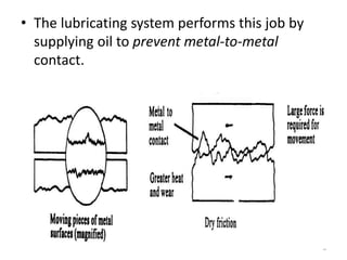
• The lubricating system performs this job by
supplying oil to prevent metal-to-metal
contact.
3
4
5
Parts of lubrication system
6
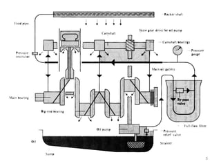
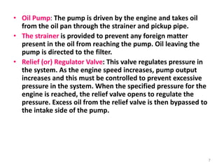
• Oil Pump: The pump is driven by the engine and takes oil
from the oil pan through the strainer and pickup pipe.
• The strainer is provided to prevent any foreign matter
present in the oil from reaching the pump. Oil leaving the
pump is directed to the filter.
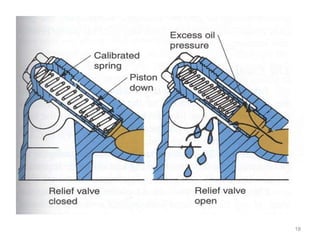
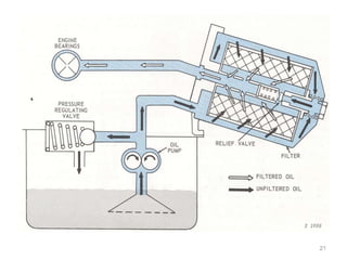
• Relief (or) Regulator Valve: This valve regulates pressure in
the system. As the engine speed increases, pump output
increases and this must be controlled to prevent excessive
pressure in the system. When the specified pressure for the
engine is reached, the relief valve opens to regulate the
pressure. Excess oil from the relief valve is then bypassed to
the intake side of the pump.
7
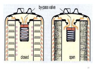
• Oil Filter: Filters out foreign particles from the
oil. The filter also includes a relief or bypass
valve which will open if the filter becomes
blocked.
• Main Oil Gallery: The main oil gallery is a
passage that runs full length of the crankcase.
A number of drillings and passages from the
gallery to other parts of the lubrication system.
8
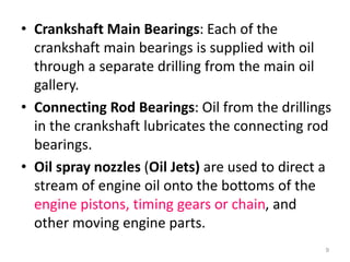
• Crankshaft Main Bearings: Each of the
crankshaft main bearings is supplied with oil
through a separate drilling from the main oil
gallery.
• Connecting Rod Bearings: Oil from the drillings
in the crankshaft lubricates the connecting rod
bearings.
• Oil spray nozzles (Oil Jets) are used to direct a
stream of engine oil onto the bottoms of the
engine pistons, timing gears or chain, and
other moving engine parts.
9
• Camshaft Bearings: The camshaft receives its oil
supply from the main oil gallery
• Rocker Shafts: Drillings in the rocker shafts provide
oil to the rocker arms and these in turn have a small
drilling to provide lubrication to the cams.
• Timing Chain: Where a timing chain is fitted, oil is
provided from the end of camshaft bearing or similar
source to that the chain and sprockets are lubricated.
• Return Oil: After lubricating the various components,
oil from the cylinder head drains back to the oil pan
through oil drain holes provided for this purpose. Oil
from the camshaft drops directly back to the oil pan.
10
Types of oil pumps
11
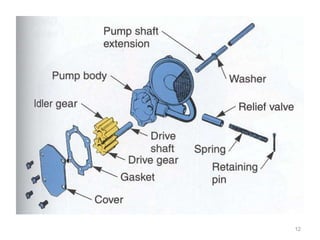
1. Gear pump
12
13
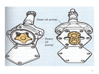
2. Rotary Oil Pumps
14
15
16
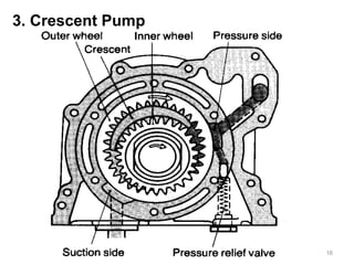
3. Crescent Pump
Pressure Relief Valve
• A pressure relief valve limits maximum oil
pressure.
• It is a spring-loaded bypass valve in the oil
pump, engine block, or oil filter housing.
17
18
OIL FILTERS
Sources of Lubricating Oil Contamination: Abrasive
and corrosive particles such as:
• carbon particles due to incomplete combustion
• Acids formed from condensed crankcase vapors
• metal particles from the wear of the metal
surfaces
• silica or dust enter through the crankcase or
carburetor intake
19
Types of oil filters
1. Full-flow filters
All the oil delivered from the pump passes
through the filter on its way to the
bearings and other engine parts, so that
only filtered oil is used for lubrication,
provided the filter is in good condition.
20
21
22
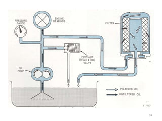
2. Bypass filters
• Bypass filters filter only a portion of the oil
delivered from the pump to the oil galleries of
the engine. An oil line is tapped into the oil
gallery and a restricted amount of oil (5-10%)
is allowed to flow to the filter and then back
to the oil pan.
23
24
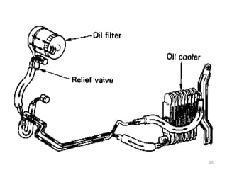
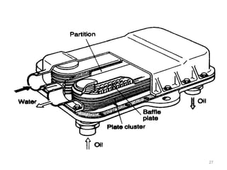
2.6 OIL COOLERS
• An oil cooler is a heat exchanger which is
either air cooled type or liquid cooled
type. In air-cooled oil cooler, oil flow
through heat exchanger tubes and coolant
(air) passing over the tubes where as in
liquid cooled cooler, both oil and coolant
(water), the two being separated by tubes
or baffles, flow through heat exchanger.
higher temperature.
25
26
27
OIL PRESSURE SWITCH
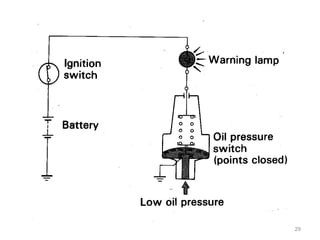
• The oil pressure switch is mounted in
the cylinder block and detects if there
is any oil pressure in the main oil
gallery.
 Low Oil Pressure
The points inside the oil pressure
switch are closed when the engine is
stopped or when the oil pressure is
low, causing the warning lamp to light
up.
28
29
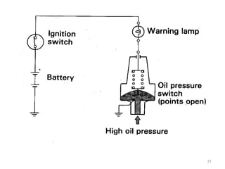
 High Oil Pressure
When the engine is started and the oil pressure
rises higher than a predetermined value, the
pressure acts on the diaphragm inside the oil
pressure switch. This causes the points of the
switch to open and the warning lamp goes
off.
30
31
LUBRICATION OF SMALL TWO AND
FOUR-STROKE ENGINES
• MIST LUBRICATION- The oil and fuel are mixed
together in proportion by volume according to
manufactures recommendation.
• SPLASH LUBRICATION-Oil held in the crankcase
is splashed by the connecting rod big end to
the cylinder.
32
CRANKCASE VENTILATION
• Crankcase ventilation is provided to remove
vapors from the crankcase (blow by gas) and
prevent their harmful effects.
• PCV- blow by gas is directed to the combustion
chamber and burned.
• NCV- blow by gas is directed to the atmosphere.
33
CLASSIFICATION OF LUBRICATION OILS
• Requirements
The following properties are required of engine
lubricating oil:
• It must have an appropriate viscosity. If it is too low,
the oil film will be broken easily and seizure of parts
will occur. If it is too high, it will create additional
resistance in parts movement and cause hard engine
starting and loss of power.
• The viscosity level must remain relatively stable
regardless of changes in temperature.
• Engine oil must be suitable for use with metals
• It must not corrode or rust parts
• It must not foam
34
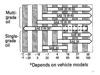
1. Classification by Viscosity
• The American Society of Automotive Engineers (SAE)
has drawn up a table of SAE viscosities classes.
• SAE indexes are usually determined according to the
temperature at which a particular oil may be used.
• Engine oil should also be carefully selected according to
the expected operating conditions of the vehicle.
• Viscosity of an oil is expressed by a number called the
viscosity index. The lower the index, the thinner the oil.
The higher the index, the thicker the oil.
35
36
• Oil whose viscosity indexes are indicated as a
range (10 W-30, 15 W-40, etc) is called "multi-
grade" oils. Since their viscosity is not affected
much by a change in temperature, they are usually
used through the year. These oils are easier
starting in cold weather and stability at high
temperatures.
37
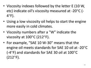
• Viscosity indexes followed by the letter E (10 W,
etc) indicate oil's viscosity measured at -20C (-
4F).
• Using a low viscosity oil helps to start the engine
more easily in cold climates.
• Viscosity numbers after a "W" indicate the
viscosity at 100C (212F).
• For example, "SAE 10 W-30" means that the
engine oil meets standards for SAE 10 oil at -20C
(-4F) and standards for SAE 30 oil at 100C
(212F).
38
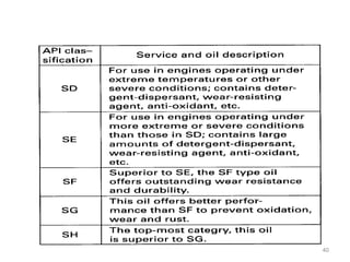
2. Classification by Quality
• Engine oil is classified by quality according
to standards set by American Petroleum
Institute (API) and by test methods also set
by API.
39
40
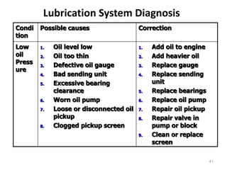
Lubrication System Diagnosis
Condi
tion
Possible causes Correction
Low
oil
Press
ure
1. Oil level low
2. Oil too thin
3. Defective oil gauge
4. Bad sending unit
5. Excessive bearing
clearance
6. Worn oil pump
7. Loose or disconnected oil
pickup
8. Clogged pickup screen
1. Add oil to engine
2. Add heavier oil
3. Replace gauge
4. Replace sending
unit
5. Replace bearings
6. Replace oil pump
7. Repair oil pickup
8. Repair valve in
pump or block
9. Clean or replace
screen
41
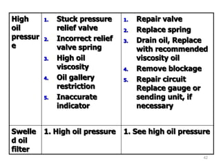
High
oil
pressur
e
1. Stuck pressure
relief valve
2. Incorrect relief
valve spring
3. High oil
viscosity
4. Oil gallery
restriction
5. Inaccurate
indicator
1. Repair valve
2. Replace spring
3. Drain oil, Replace
with recommended
viscosity oil
4. Remove blockage
5. Repair circuit
Replace gauge or
sending unit, if
necessary
Swelle
d oil
filter
1. High oil pressure 1. See high oil pressure
42