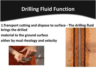
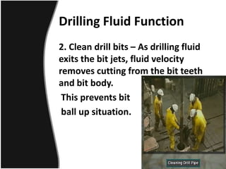
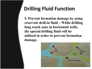
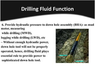
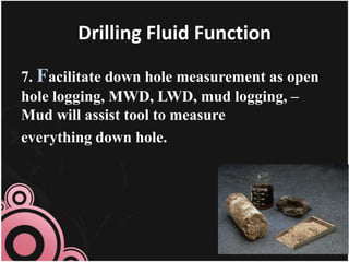
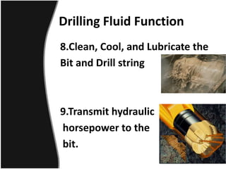
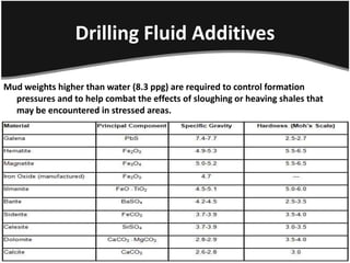
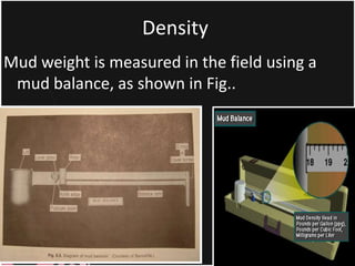
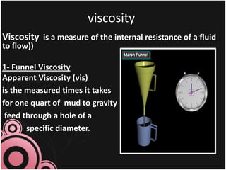
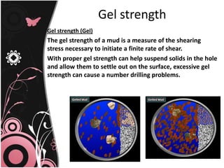
3. INTRODUCTION
The drilling-fluid system—commonly known as the “mud
system”—is the single component of the well-
construction process that remains in contact with the
wellbore throughout the entire drilling operation.
Drilling-fluid systems are designed and formulated to
perform efficiently under expected wellbore
conditions.
Advances in drilling-fluid technology have made it
possible to implement a cost-effective, fit-for-purpose
system for each interval in the well-construction
process.
4. Drilling Fluid Function
1.Transport cutting and dispose to surface - The drilling fluid
brings the drilled
material to the ground surface
either by mud rheology and velocity
5. Drilling Fluid Function
2. Clean drill bits – As drilling fluid
exits the bit jets, fluid velocity
removes cutting from the bit teeth
and bit body.
This prevents bit
ball up situation.
6. Drilling Fluid Function
3. Provide hydrostatic pressure to control well
while drilling –Hydrostatic pressure
provided from drilling fluid is the primary
well control. Mud weight should be high
enough
to control formation pressure while
drilling.
7. Drilling Fluid Function
4. Prevent excessive mud loss -
While drilling, clay particle will
form a thin layer over porous
zones called “mud cake” or
“filter cake”. Mud cake acts as
barrier to prevent excessive
drilling fluid loss into formation
and provides wellbore stability..
8. Drilling Fluid Function
5. Prevent formation damage by using
reservoir drill-in fluid – While drilling
long reach zone in horizontal wells,
the special drilling fluid will be
utilized in order to prevent formation
damage.
9. Drilling Fluid Function
6. Provide hydraulic pressure to down hole assembly (BHA)- as mud
motor, measuring
while drilling (MWD),
logging while drilling (LWD), etc
– Without enough hydraulic power,
down hole tool will not be properly
operated, hence, drilling fluid plays
essential role to provide power to
sophisticated down hole tool.
10. Drilling Fluid Function
7. Facilitate down hole measurement as open
hole logging, MWD, LWD, mud logging, –
Mud will assist tool to measure
everything down hole.
14. Drilling Fluid Selection
The following requirements and criteria should be
applied when considering the selection of drilling
fluid or fluids for a particular well. It should be
noted that it is common to utilise two or three
different fluid types on one well.
Pore pressure /fracture gradient plots to
establish the minimum / maximum mud
weights to be used on the whole well,
15. Drilling Fluid Selection
Offset well data (drilling completion reports, mud recaps, mud
logs etc.) from similar wells in the area to help establish
successful systems, problematic formations, potential hazards,
estimated drilling time etc.
Geological plot of the prognosed lithology.
Casing design to give each casing point and the casing
programmer. This will give a good indication of what the mud has
to deal with per hole section i.e. formation type, hole size and
length etc.
Basic mud properties required over each hole section.
16. Drilling Fluid Additives
There are many drilling fluid additives which are used to either change the mud
weight(density) or change its chemical properties .
1.Weighting Materials:
Weighting materials (densifiers) are compounds that are dissolved or suspended
in drilling fluid to increase its density. They are used to control formation
pressures and to help combat the effects of sloughing or heaving shales that
may be encountered in stressed areas.
Any substance that is denser than water and that does not adversely
affect other properties of the drilling fluid can
be used as a weighting material
17. Drilling Fluid Additives
Mud weights higher than water (8.3 ppg) are required to control formation
pressures and to help combat the effects of sloughing or heaving shales that
may be encountered in stressed areas.
18. Materials used as densities
Barite
Barite is preferred to other weighting materials
because of its low cost and high purity.
Barite is normally used when mud weights in excess
of 10 ppg are required.
Barite can be Aa very high muds weights (22.0 ppg))
the rheological properties of the fluid used to
achieve densities up to (22.0 ppg) in both water-
based and oil -based muds. become extremely
difficult to control affected due to the increased
solids content.
19. Materials used as densities
2. Iron Minerals
Iron ores have specific gravities in excess of 5.
They are more erosive than other weighting materials and may
contain toxic materials.
The mineral iron comes from several iron ores sources including:
haematite/magnetite, Illmenite and siderite. Iron ores are
available in nearly unlimited quantities worldwide.
Because iron ores always contain impurities, problems such as
thickening of muds and temperature instability are seen in
water- based fluids weighted with ground, naturally
occurring iron ores
The most commonly used iron minerals are:
Iron Oxides
Iron Titanate:
Iron Carbonate
20. Materials used as densities
3. Calcium Carbonates
Calcium carbonate (CaCO3) is one of the most useful weighting agents especially in no
damaging
drilling fluids. Its main advantage comes from the its ability to react and dissolve in
hydrochloric acid. Hence any filter cake formed on productive zones can be easily
removed thereby enhancing production. Calcium carbonate is dispersed in oil muds
more
4. Lead Sulphides
5. Soluble Salts
21.
22. Materials used as Viscosifiers
1.Clays are added to water to provide the viscosity and
yield point properties necessary to lift the drilling
cutting or to keep them in suspension.
There are two types of clay currently in use for making
water-base muds.
Bentoniticclay (using in fresh water)
Attapulgite(or salt gel) (using in both fresh and saltwater).
2. Polymers are chemicals consistingof chains made up of
manyrepeated small units called monomers
23. Types of drilling Fluid
Three types of drilling mud are in common use:
water-base mud
oil-base mud
Gas based fluids
Water Base Mud
This fluid is the mud in which water is the continuous phase. This is the most
common drilling mud used in oil drilling.
The following designations are normally used to define the classifications of water
base drilling fluid
24. the classifications of water base
drilling fluid
Non-dispersed-Non - inhibited
Non-dispersed -
Inhibited
Dispersed -
Non-inhibited
Dispersed -
Inhibited
25. Oil base mud
This drilling mud is made up of oil as
the continuous phase. Diesel oil is
widely used to provide the oil phase.
This type of mud is commonly used in
swelling shale formation.
There are two types of oil-based muds:
• Invert Emulsion Oil Muds.
• Pseudo Oil Based Mud .
26. Disadvantage of Oil-base mud
The main disadvantage of Oil-base mud are:
the environment is contaminated
flammability becomes a hazard drilled-solids
removal from an oil-base mud is usually more
difficult than from a water-base mud.
electric logging is more difficult with
oil-base mud
27. gas based fluids
There are four main types of gas based
fluids:
1. Air
2. Mist
3. Foam
4. Aerated Drilling Fluid
28. Drilling Fluids Properties
Mud weight or mud density.
Funnel Viscosity.
Plastic Viscosity (PV).
Gel Strengths.
Yield Point.
Fluid Loss and Filter Cake.
29. Density
((Any accepted terminology that indicates the weight per
unit volume of drilling fluid))
-Pounds per gallon (ppg).
-Pounds per cubic feet (pcf).
-Gram per cubic centimeter (g/cc).
-Kilogram per liter (kg/l).
31. viscosity
Viscosity is a measure of the internal resistance of a fluid
to flow))
Funnel Viscosity
-
1
Apparent Viscosity (vis)
is the measured times it takes
for one quart of mud to gravity
feed through a hole of a
specific diameter.
32. Viscosity
2. Plastic viscosity (Pv)
is that part of flow resistance in a mud caused primarily by the friction
between the suspended particles and by the viscosity of the continuous
liquid phase
The viscosities are defined as follows:
p = 600 - 300
aF = ½ 600
Yb = 300 - p
Where p = plastic viscosity, cp
aF = apparent viscosity, cp
Yb = Bingham yield point, lb/100 ft2
= Torque readings from instrument dial at 600 and 300 rpm.
33.
34. Gel strength
Gel strength (Gel)
The gel strength of a mud is a measure of the shearing
stress necessary to initiate a finite rate of shear.
With proper gel strength can help suspend solids in the hole
and allow them to settle out on the surface, excessive gel
strength can cause a number drilling problems.
35.
36. Yield point (Yp)
is a measurement under flowing conditions of the
forces in the mud which cause gel structure to
develop when the mud is at res
Fluid Loss and Filter Cake
The filtration, water loss or wall building test is
conducted with a filter press.
The rate at which filtrate will invade permeable zone
and the thickness of the filter cake that will be
deposited on the wall of the hole as filtration
takes place are important keys to trouble-free
drilling
38. Drilling hazards
The following are some of the most common hazards in drilling and
can be overcome by proper control of the mud properties.
.Salt section hole enlargement
1
Salt section can be eroded by the drilling fluid and causes
hole enlargement. These enlargement will require larger
mud volume to fill the system and in case of casing the
hole, larger cement volume is required.
To avoid these problems a
salt saturated mud system is prepared
prior to drilling the salt bed.
39. 2.Heaving shale problems
Areas with shale sections containing bentonite or other
hydratable clays will continually absorb water, swell and
slough into the hole.
Such beds are referred to as heaving shales and constitute a
severe drilling hazard when encountered.
Pipe sticking, excessive solid buildup in the mud and hole
bridging are typical problems.
Various treatments of the mud are sometimes successful, such
as
Changing mud system to high calcium content by adding lime,
gypsum etc which reduces the tendency of the mud to
hydrate water sensitive clays.
Increasing circulation rate for more rapid removal of
particles.
Increasing mud density for greater wall support
Decreasing water loss mud
Changing to oil emulsion mud
Changing to oil-based mud.
40. 3.Blowouts
Blowout is the most spectacular, expensive and highly feared hazard of
drilling.
This occurs when encountered formation pressure exceed the mud column
pressure which allows the formation fluids to blow out of the hole.
Mud density or the mud weight is the principal factor in controlling this
hazard.
In drilling a blow out preventer (BOP) stack is always attached at the top of
the conductor pipe. In case of a gas kick (a sign that may lead to a blow
out) the BOP stack can close the annular space between the drilling pipe
and the conductor pipe or casing or shut the whole hole (with a blind ram
of the BOP).
41. 4.Lost Circulation
Lost circulation means the loss of
substantial amount of drilling mud to an
encountered formation.
Lost circulation materials are commonly
circulated in the mud system both as a
cure and a continuous preventive.
These materials are the fibrous materials
such as the hay, sawdust or padi husk
and lamellated (flat and platy) materials
such as mica, cellophane.