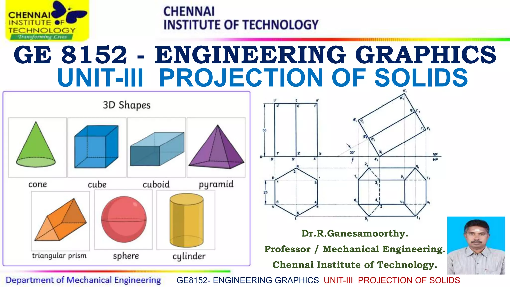
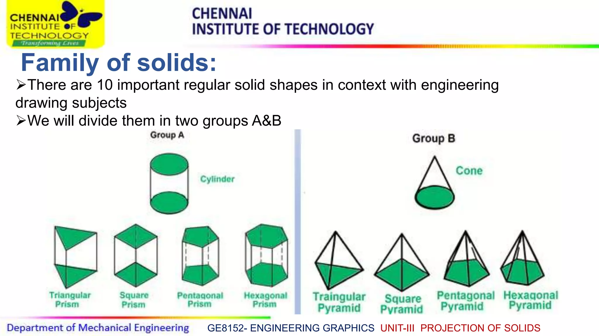
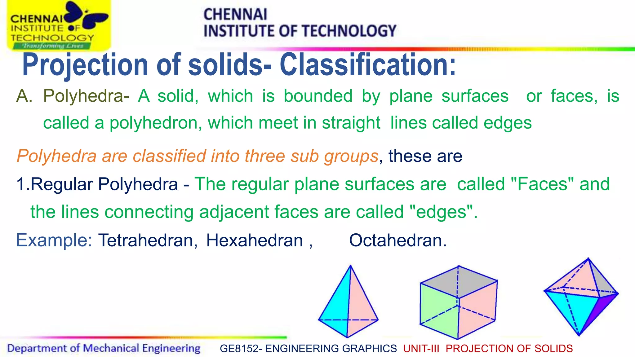
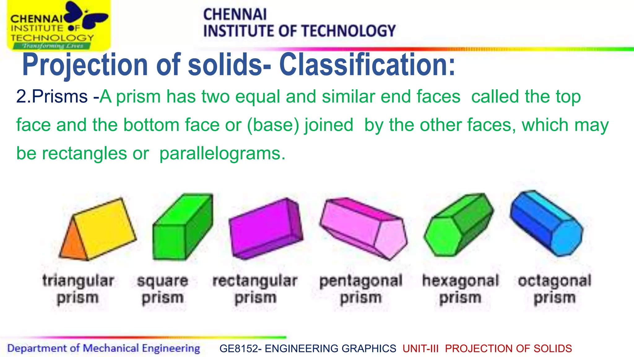
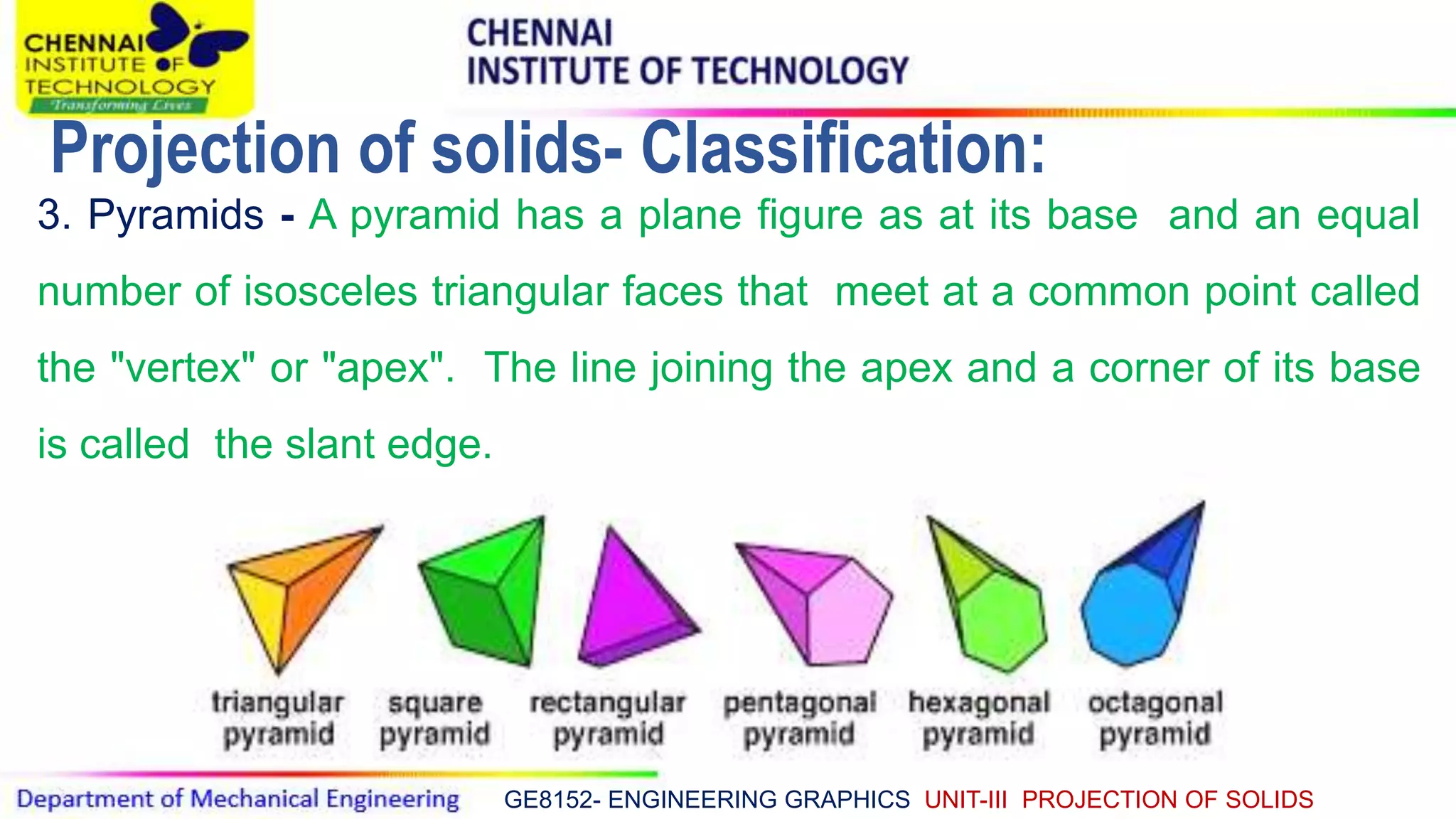
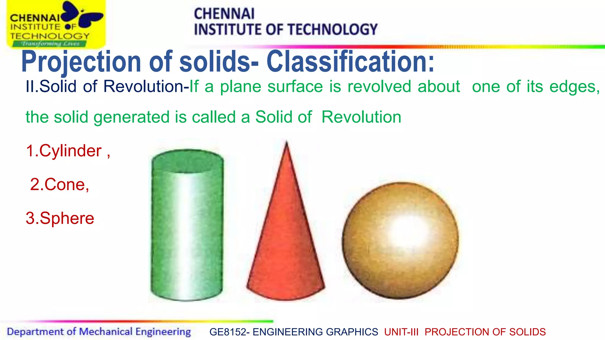
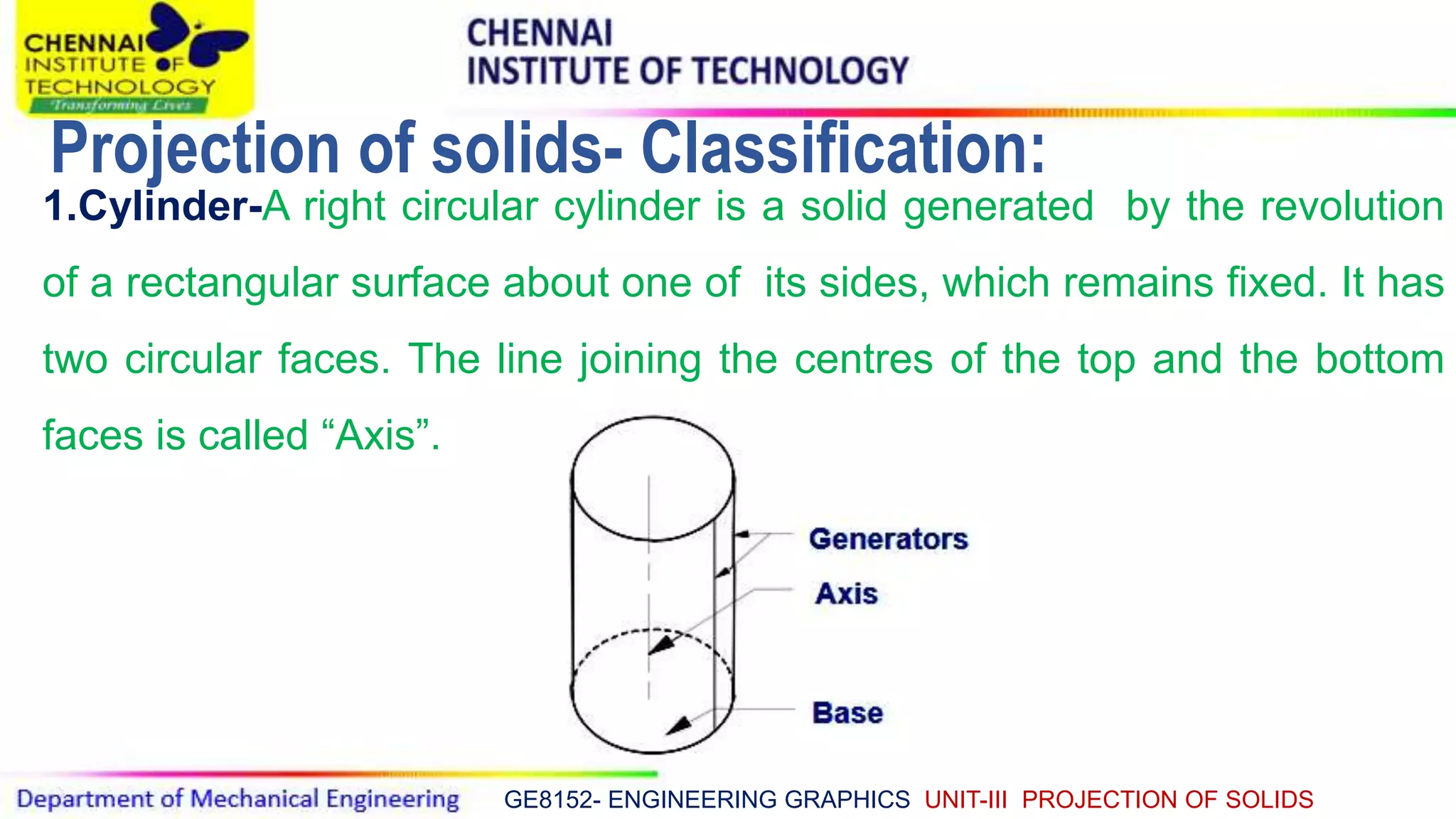
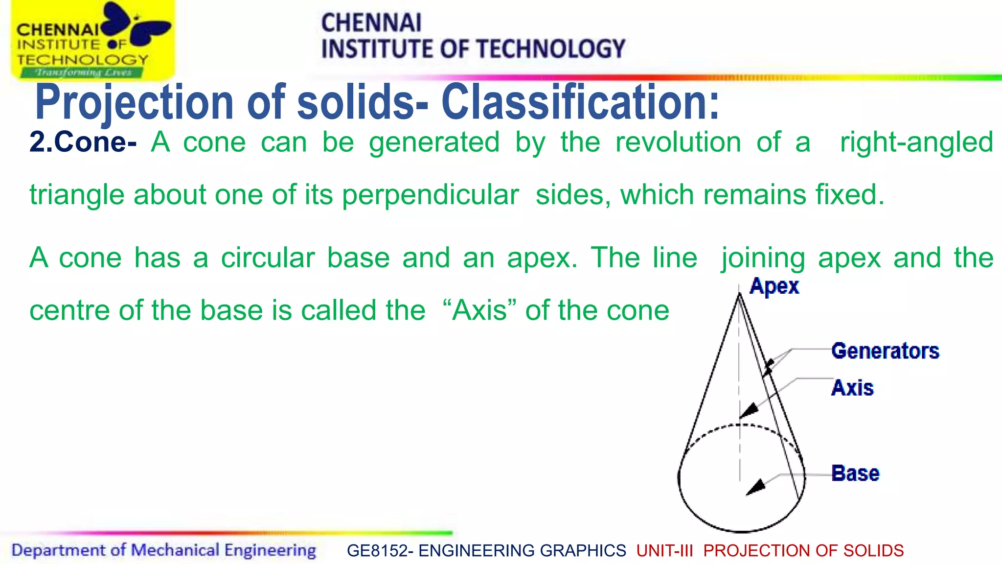
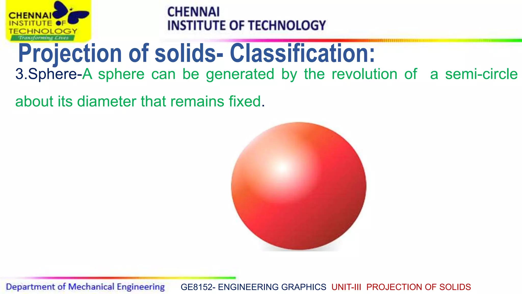
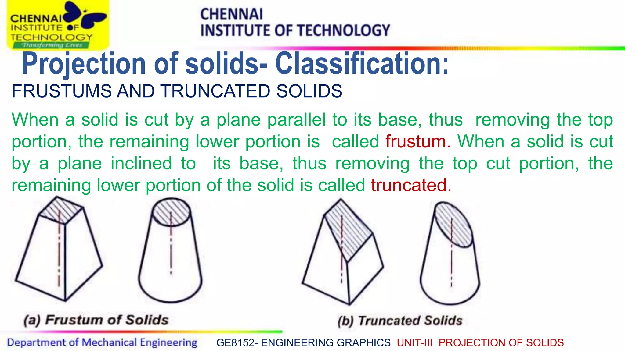
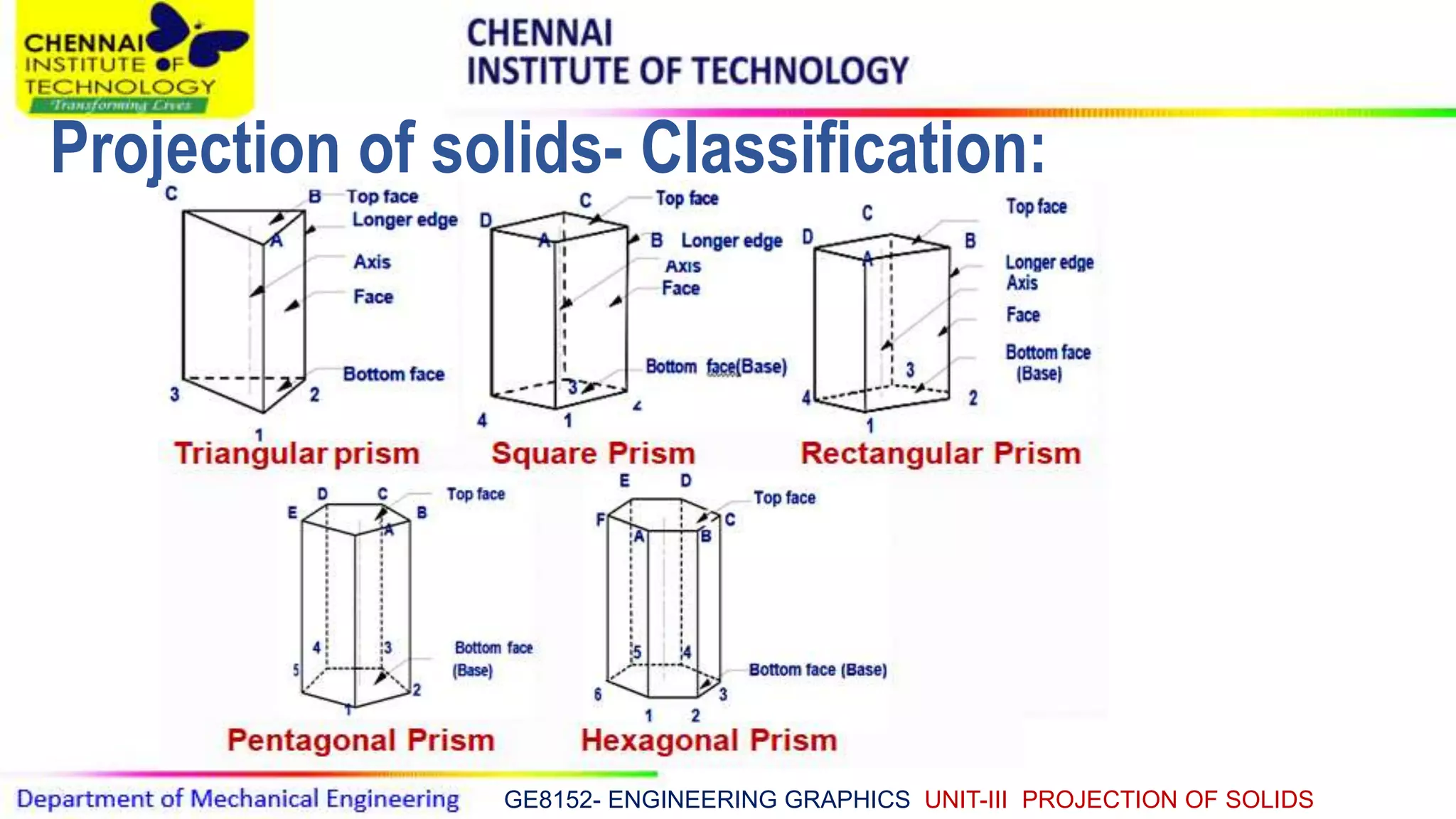
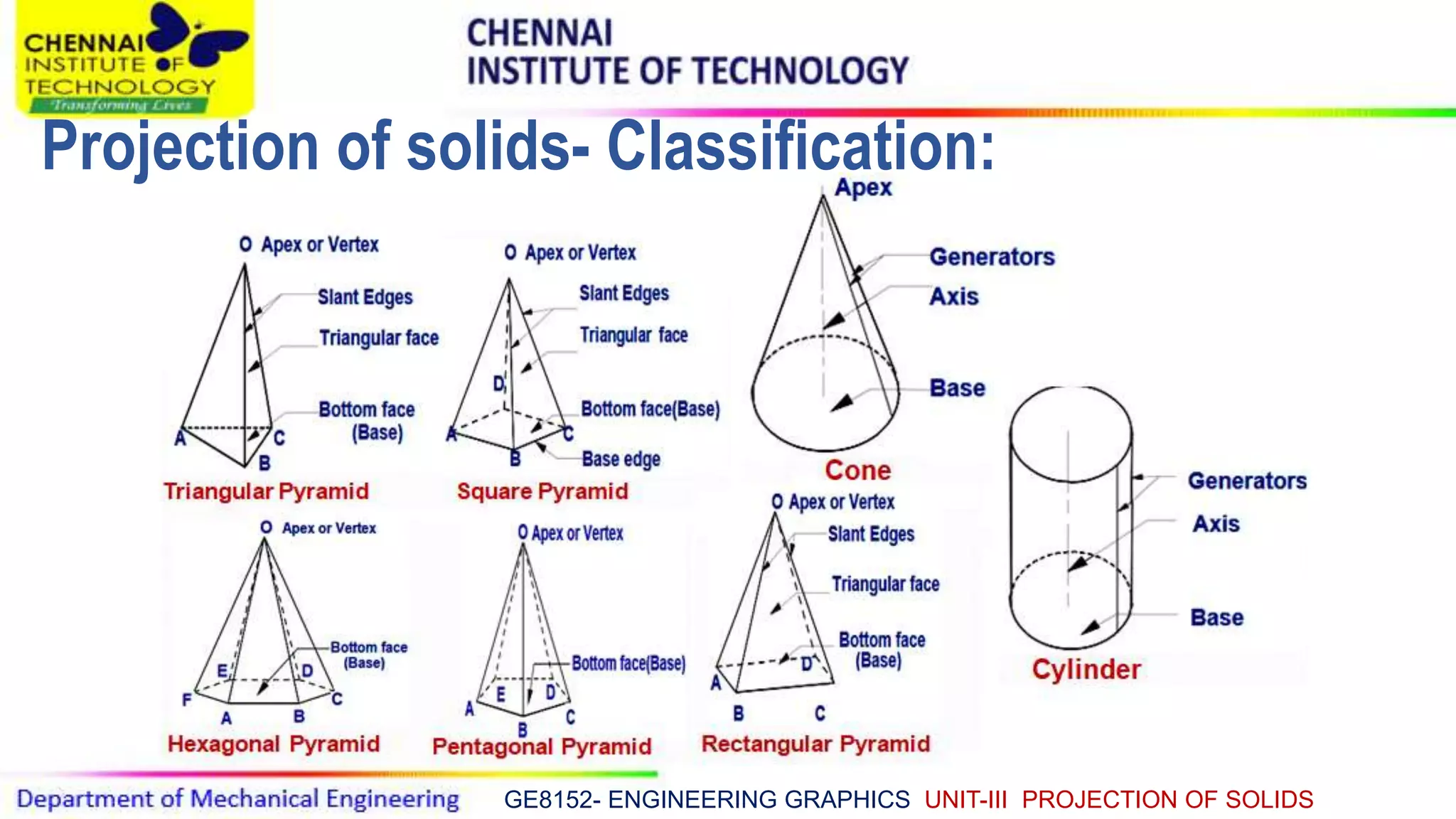
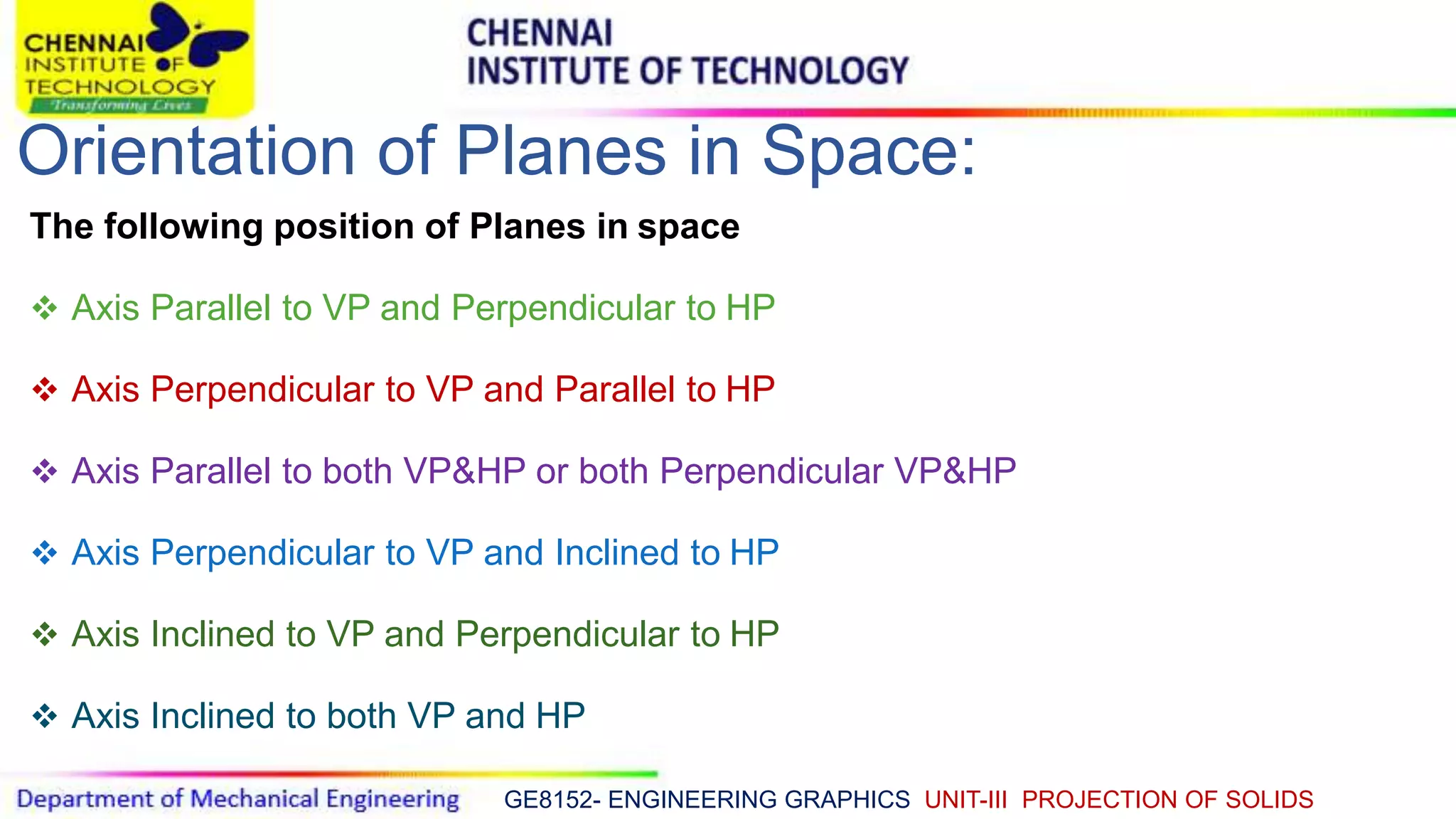
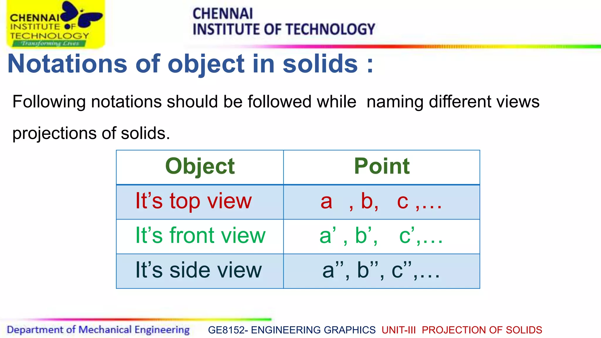
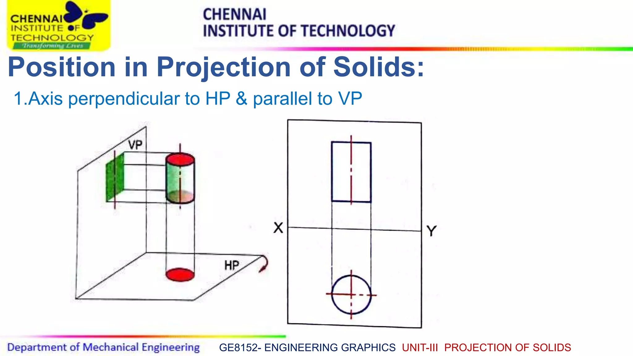
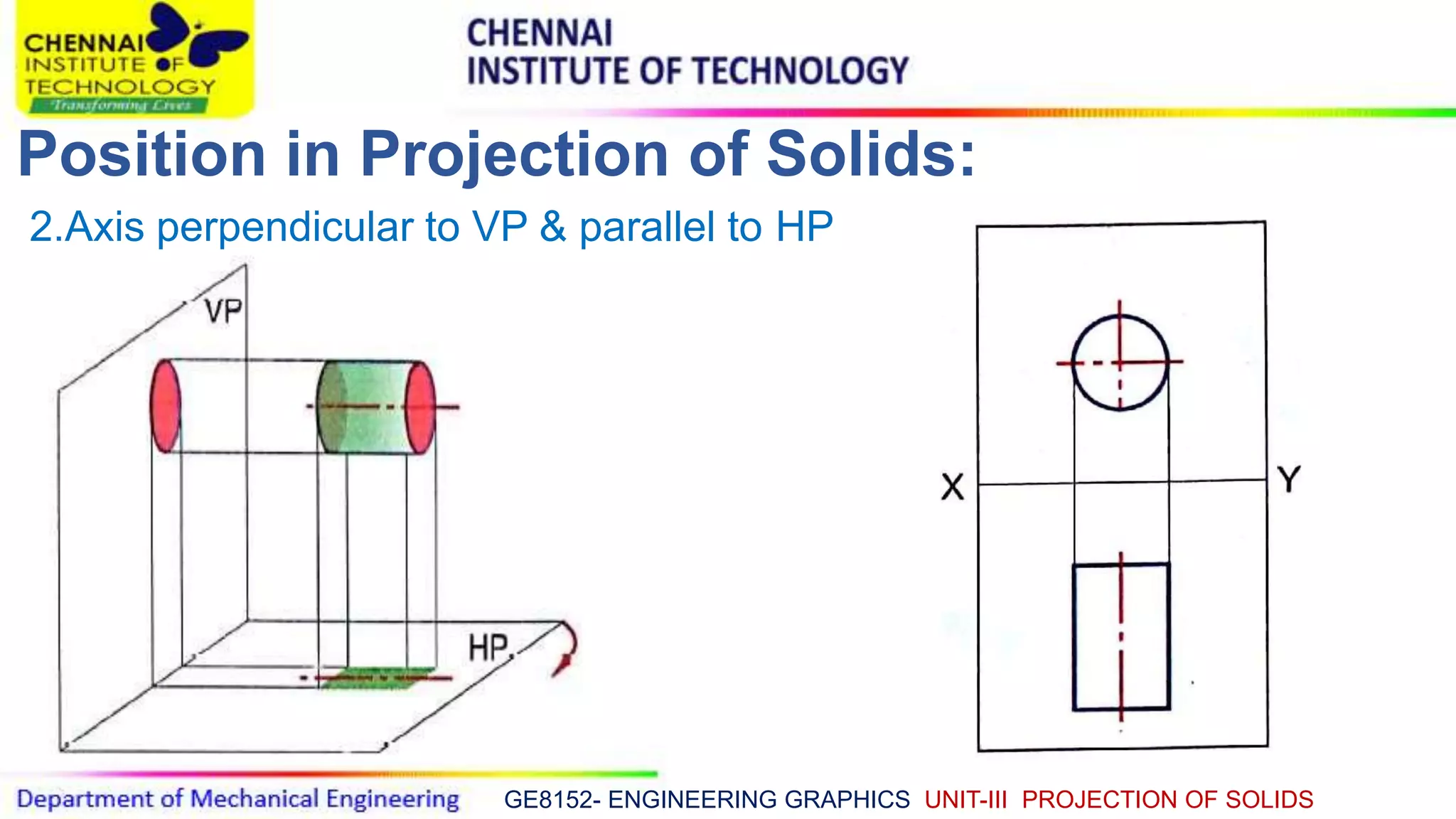
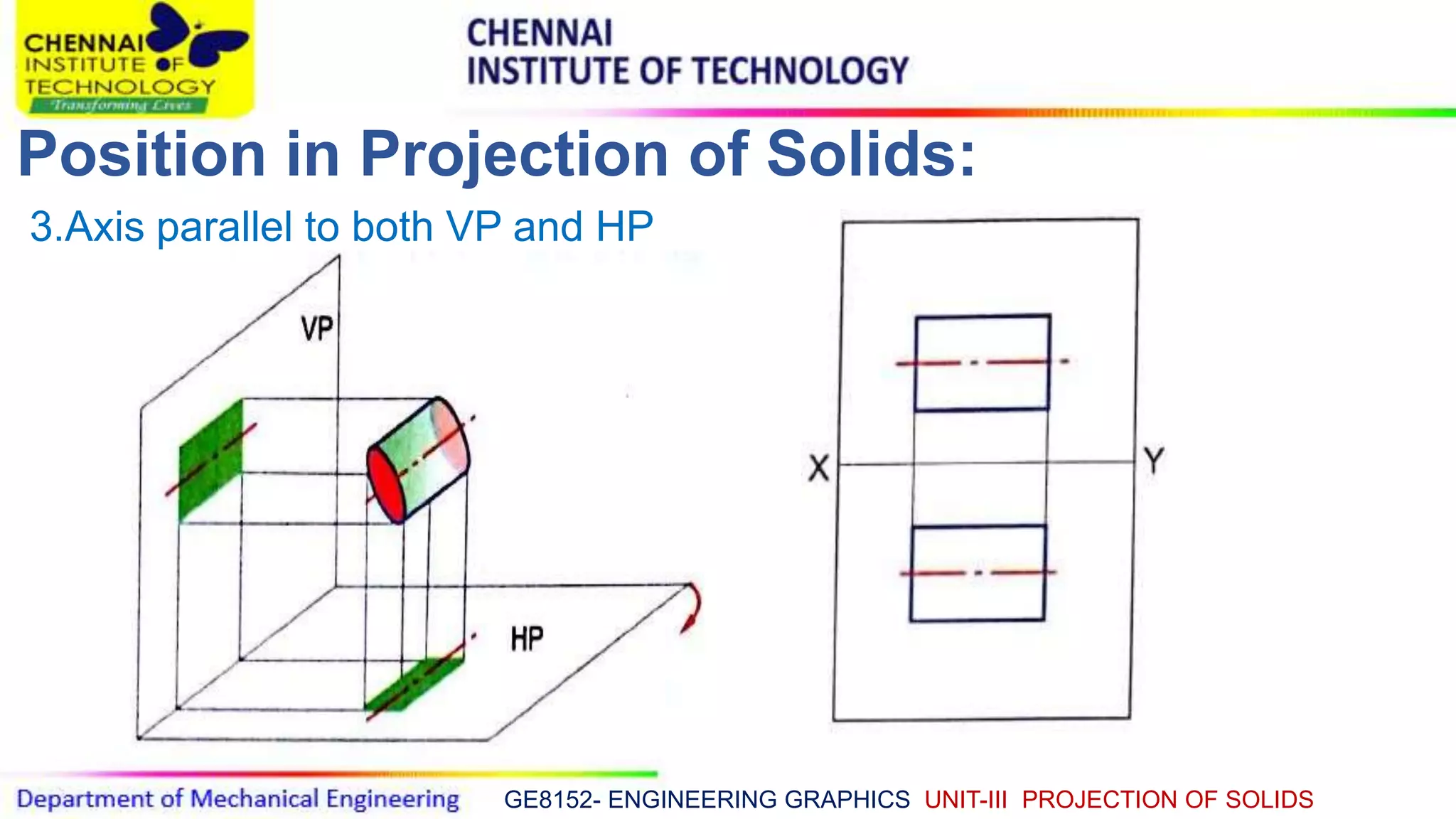
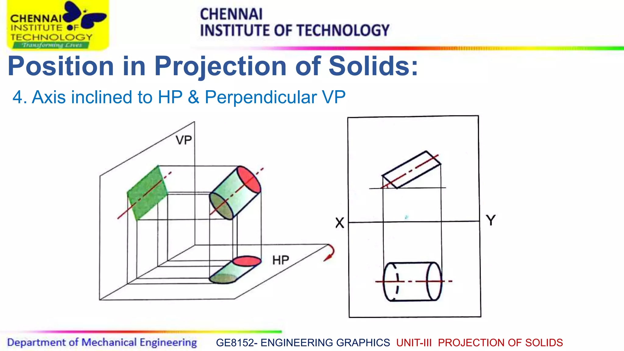
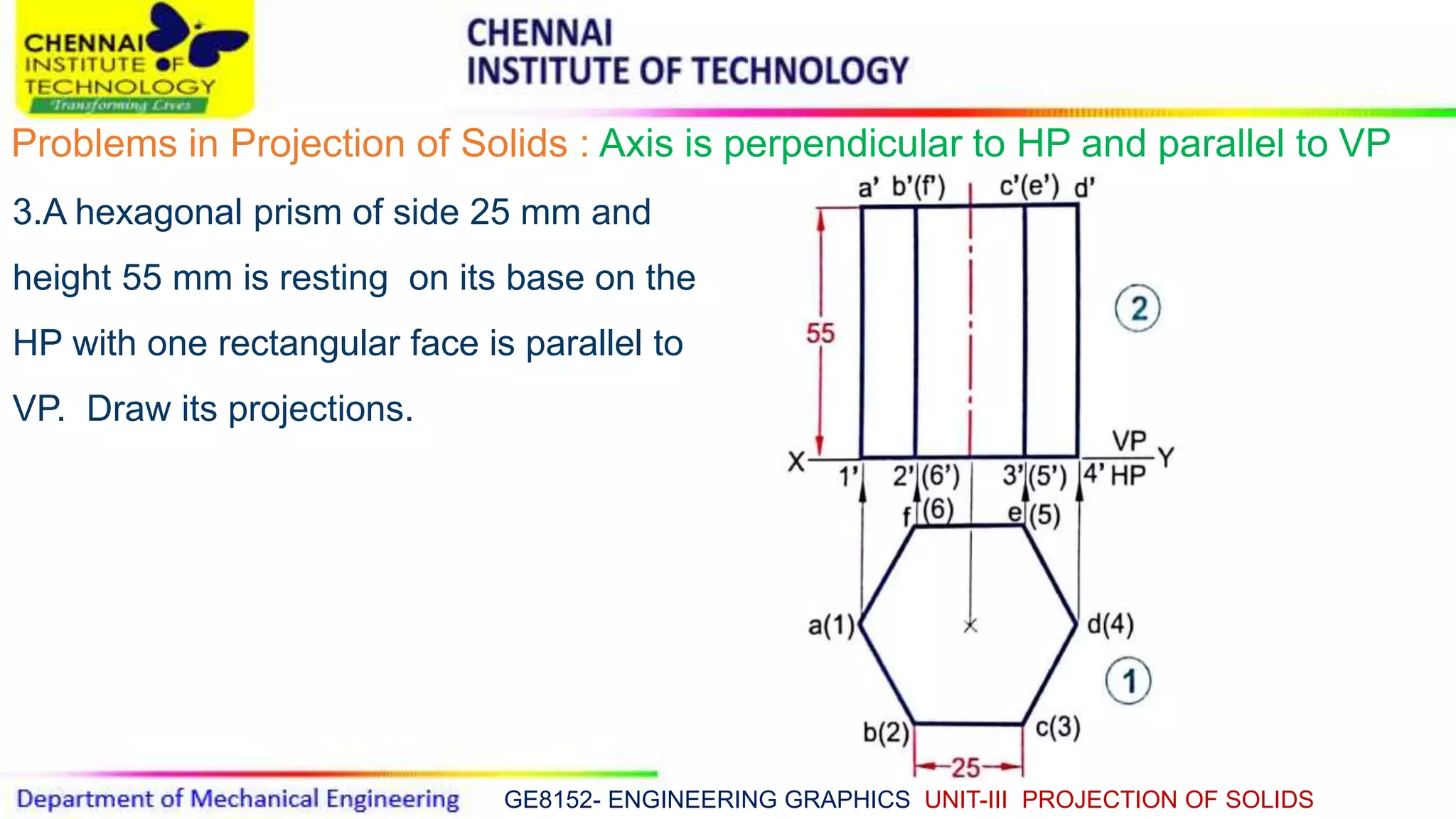
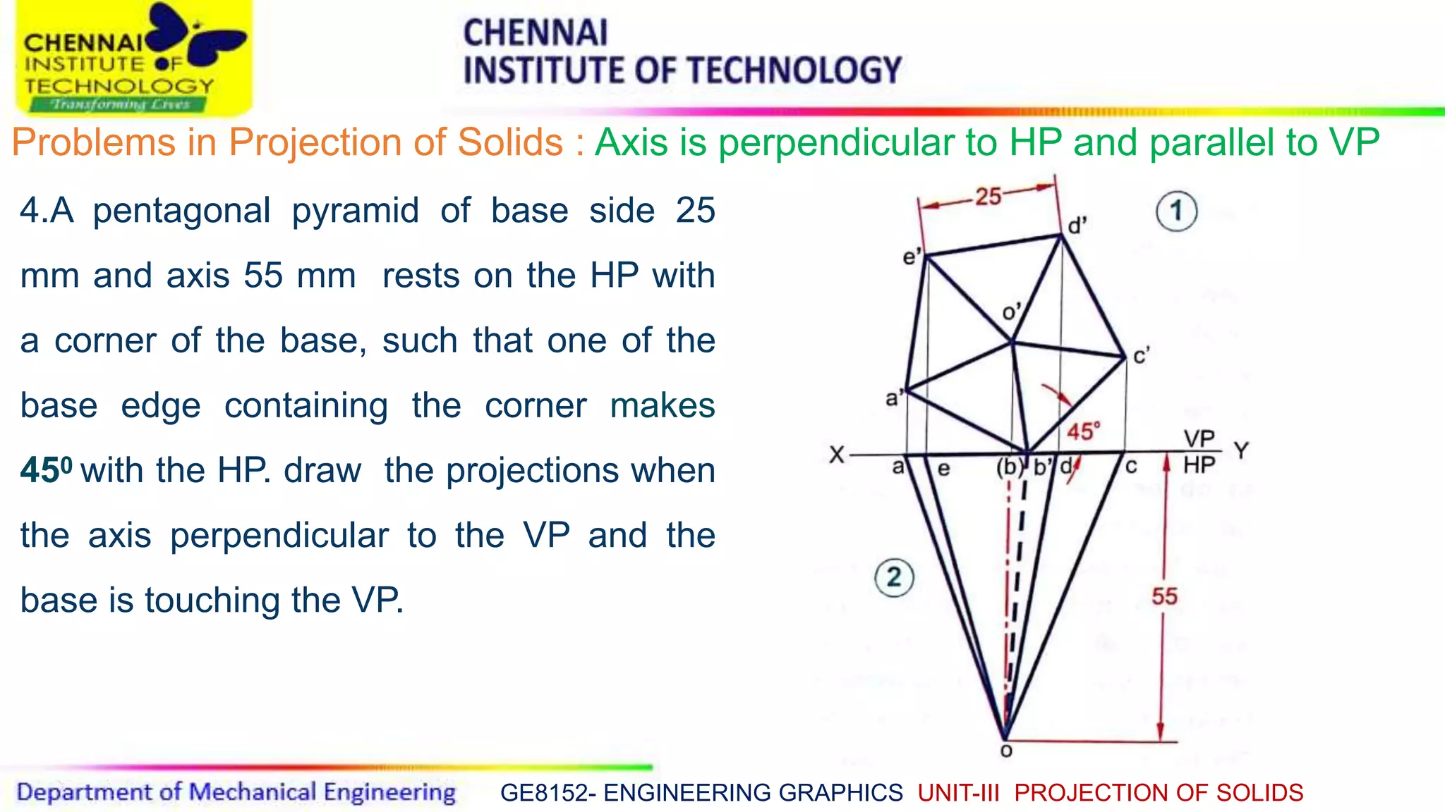
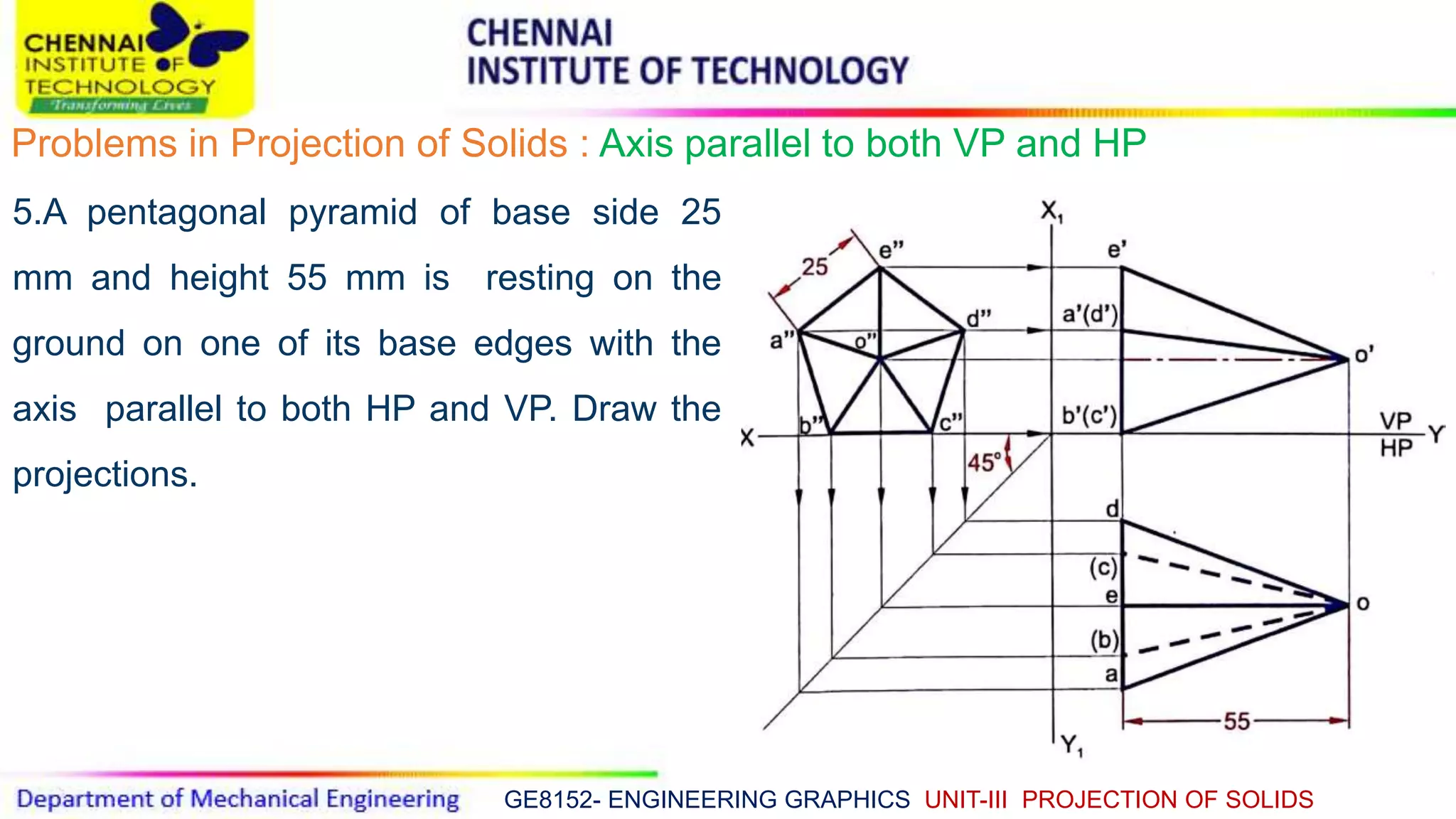
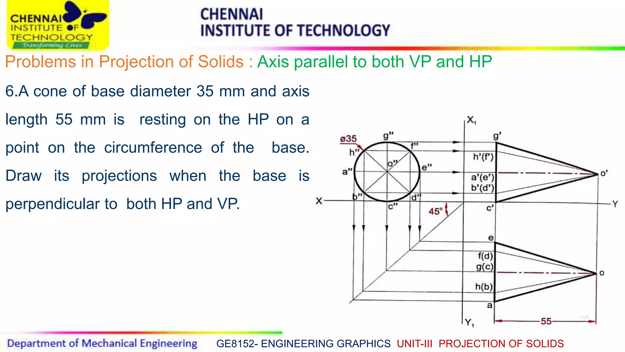
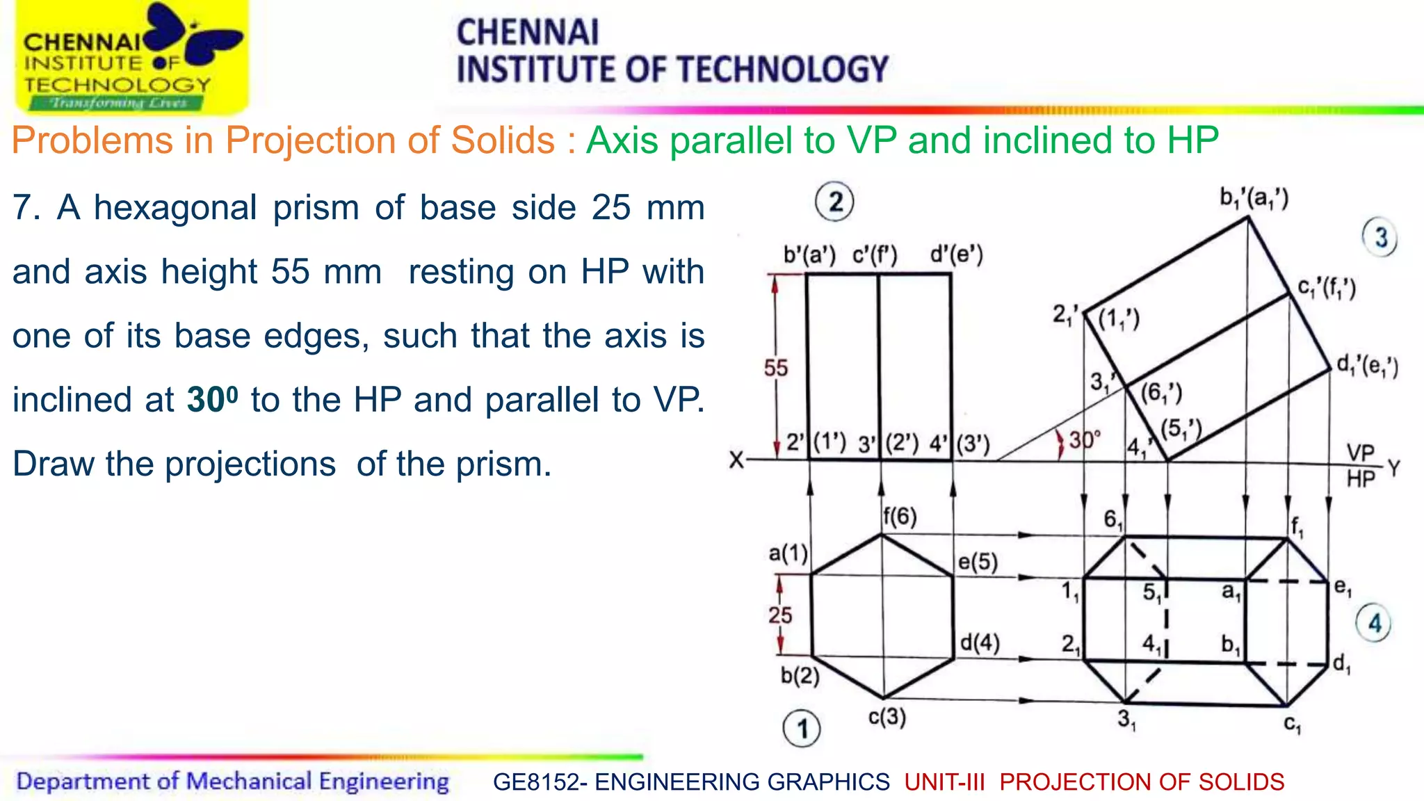
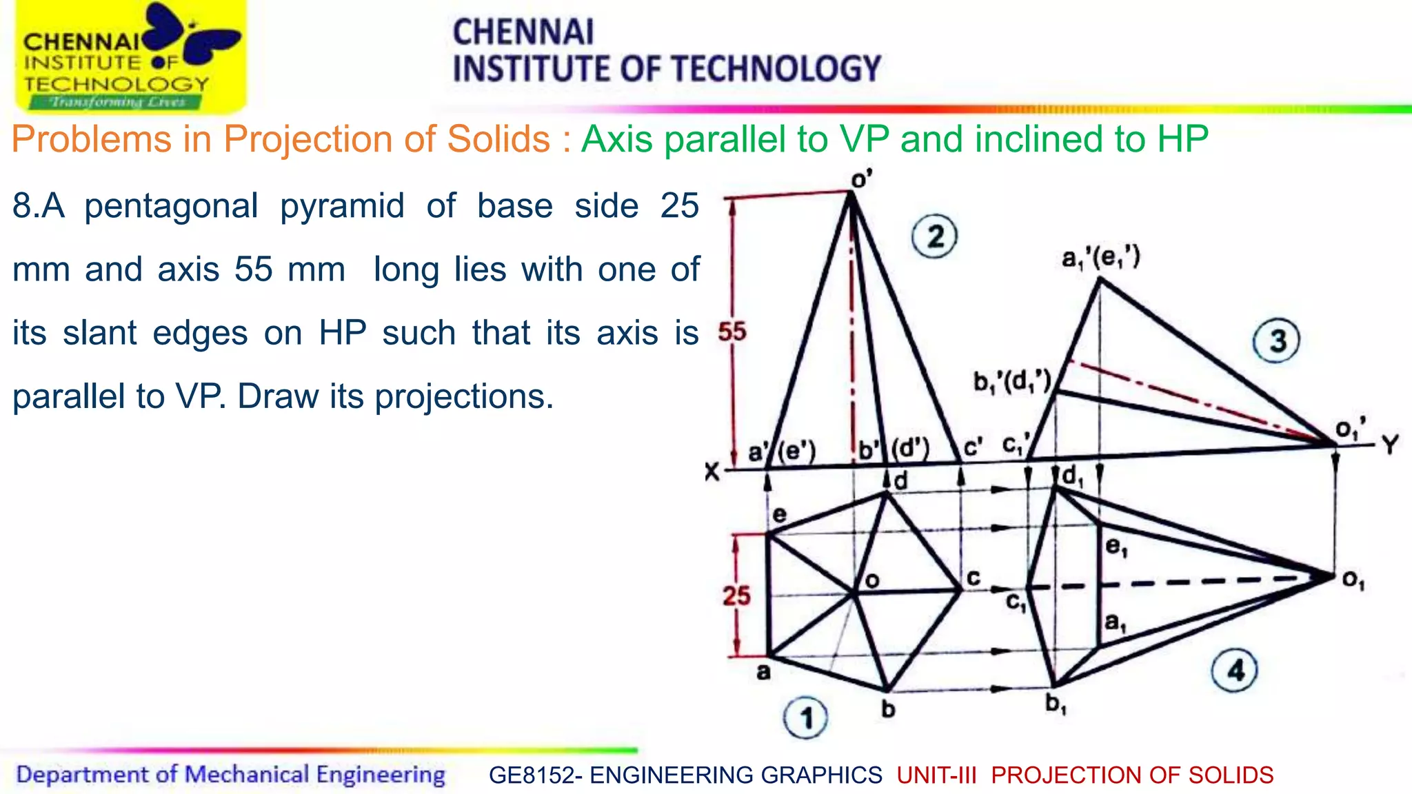
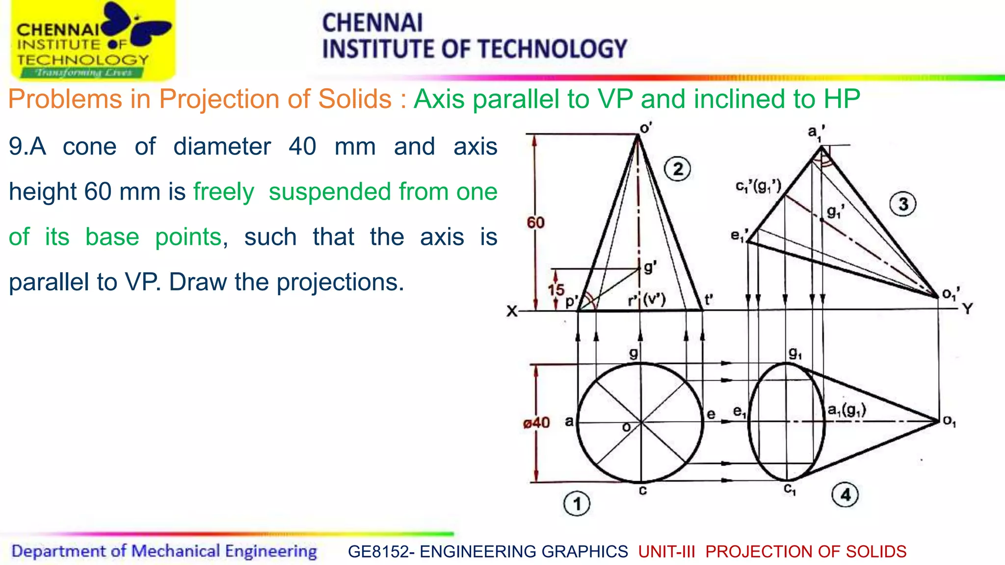
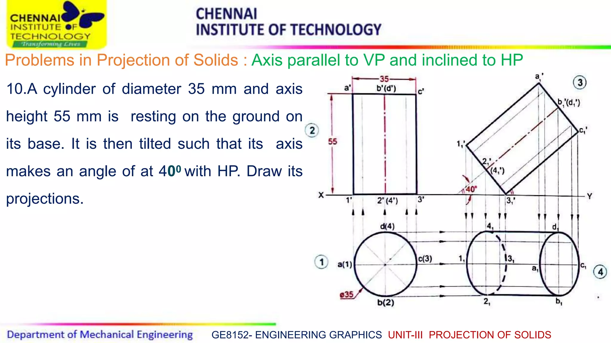
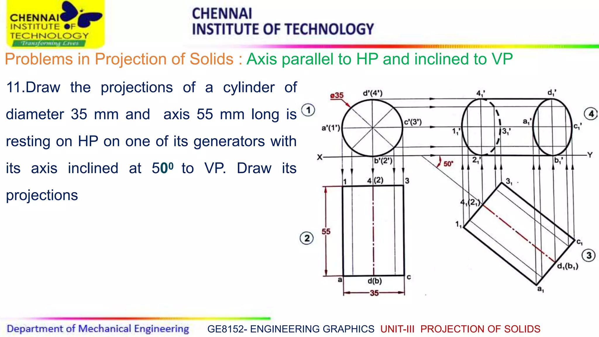
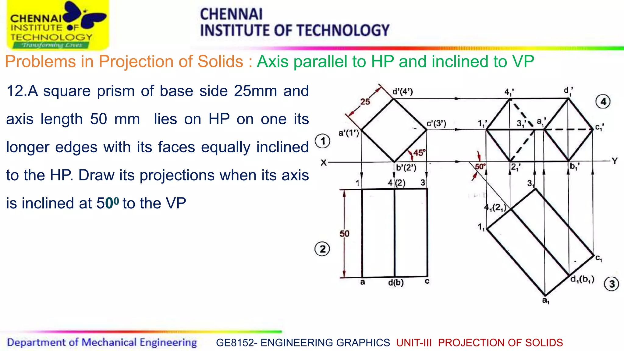
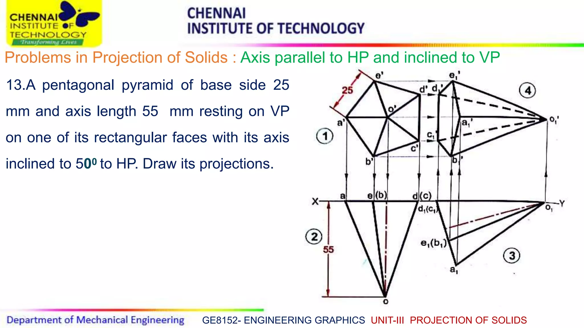
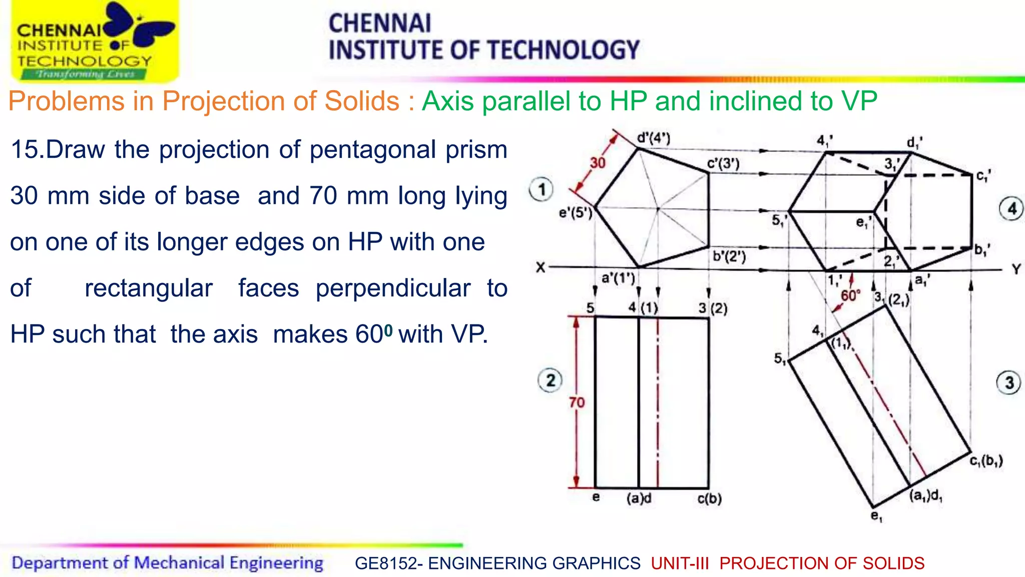
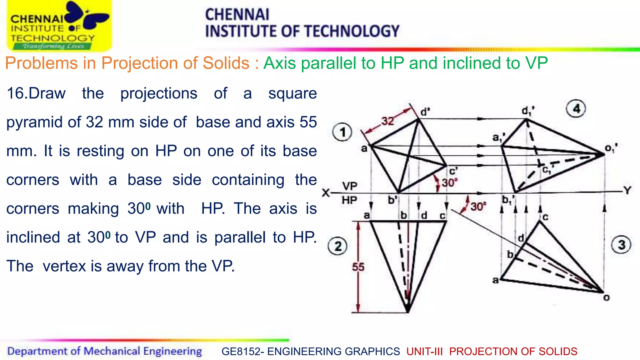
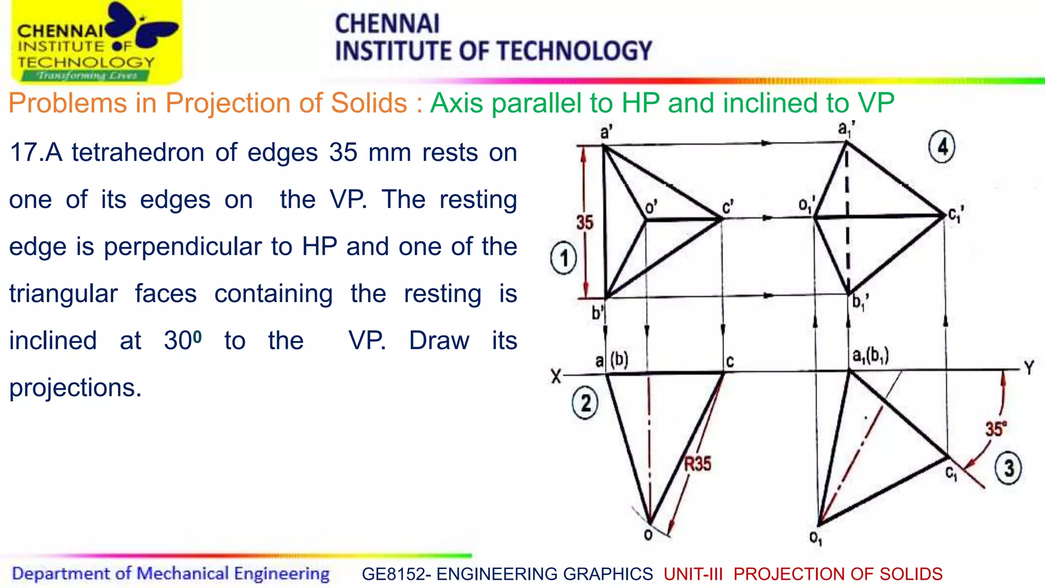
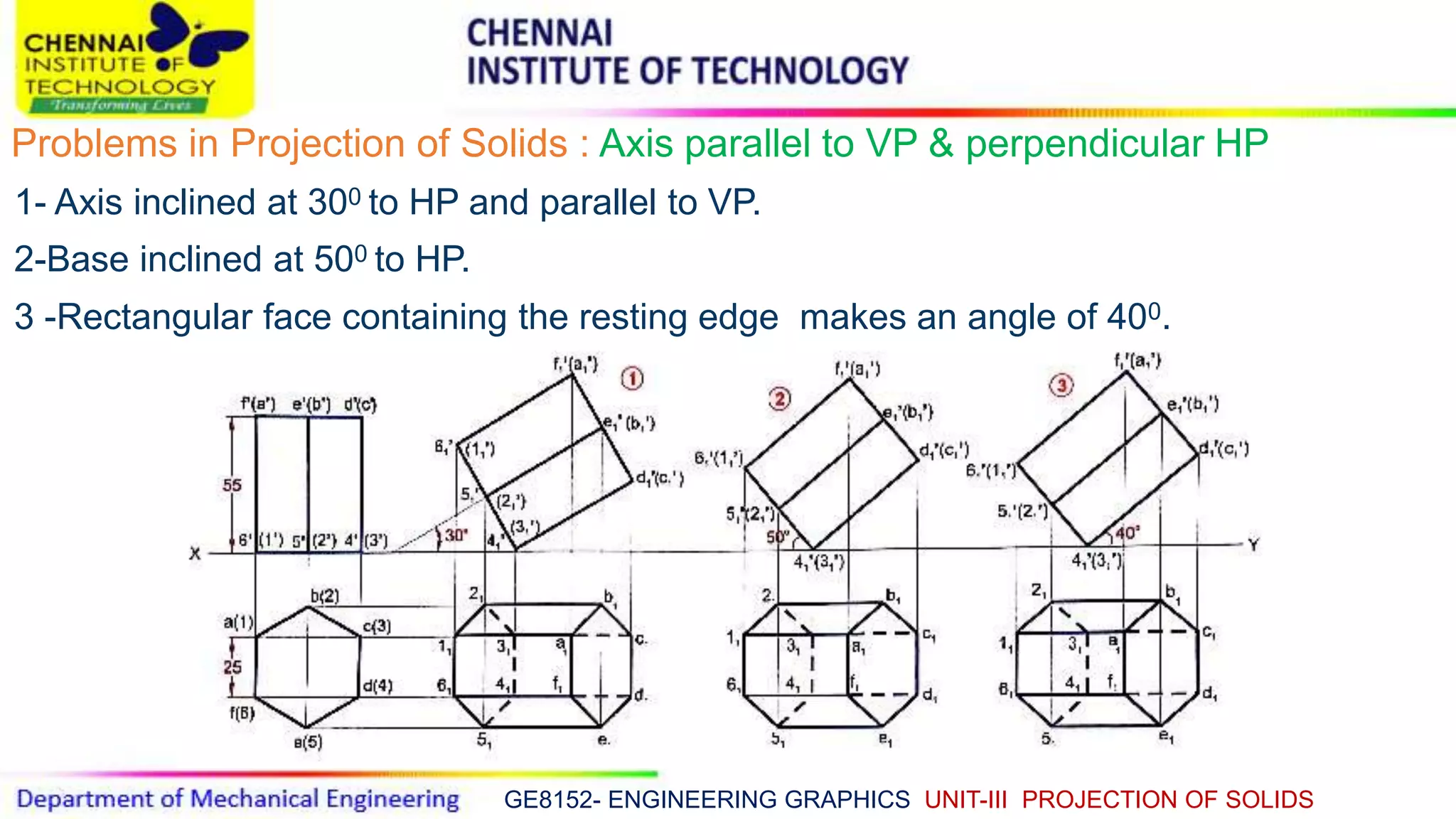
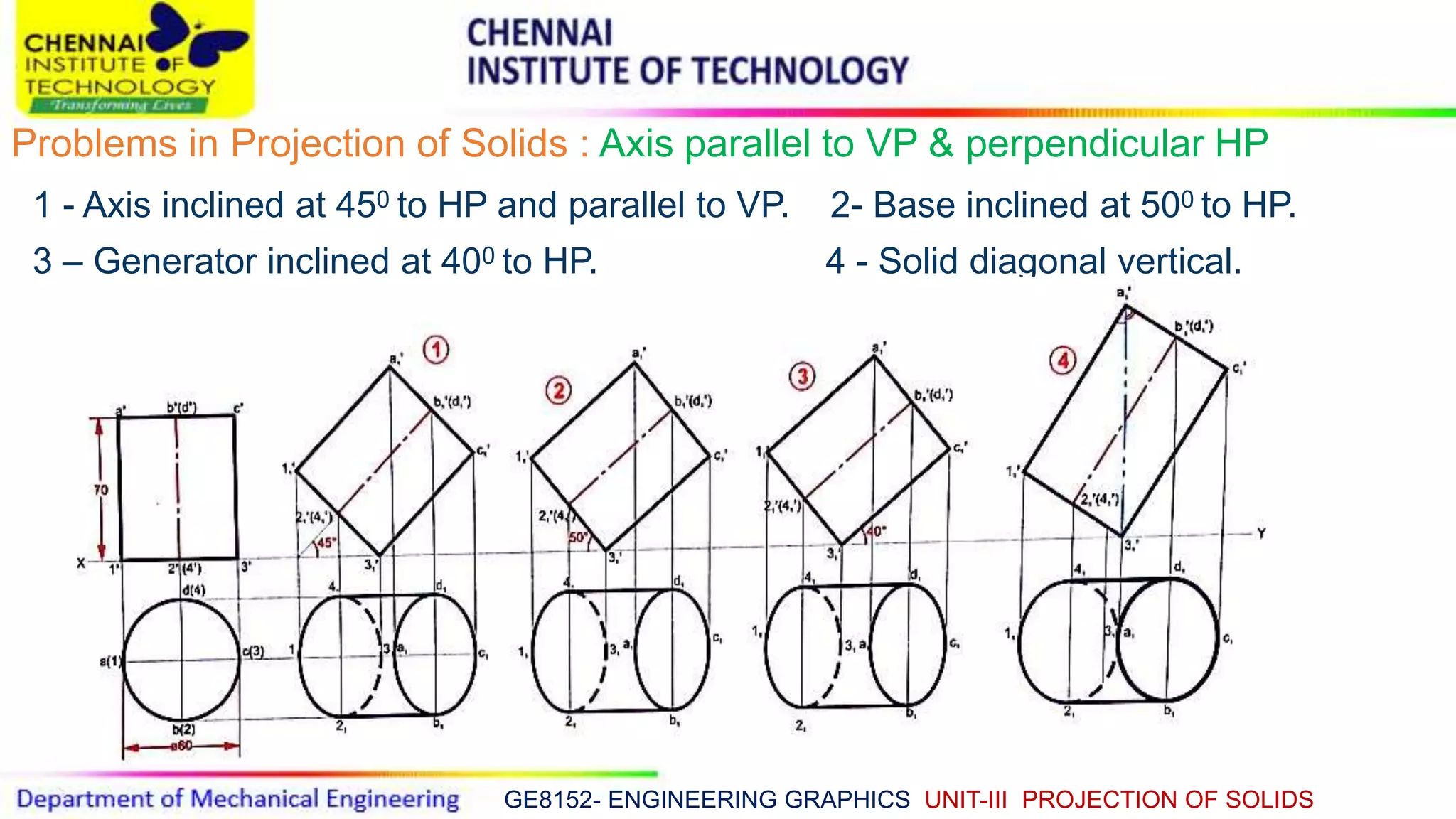
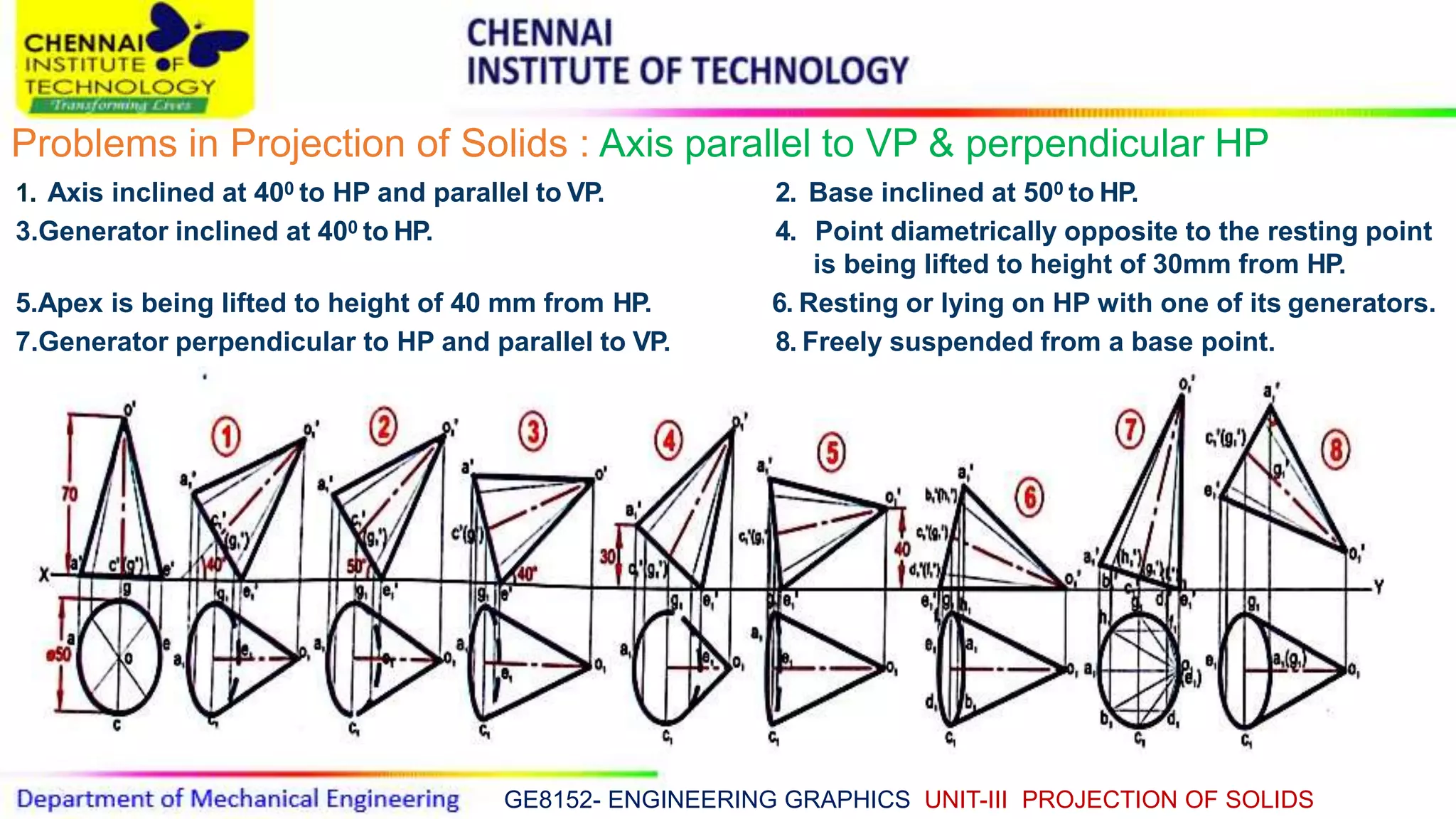
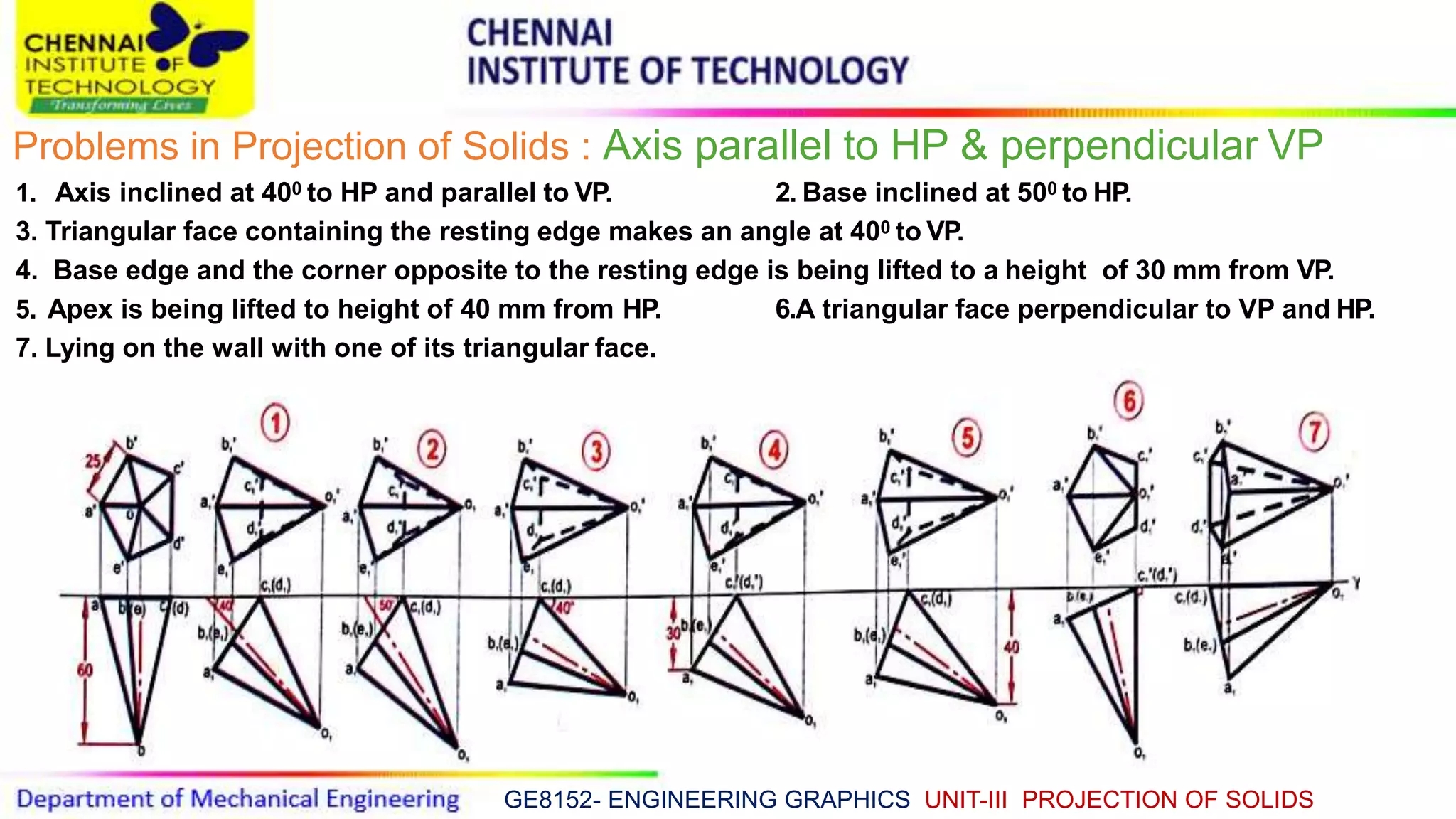
This document discusses the projection of solids in engineering graphics. It begins by defining a solid as an object with three dimensions - length, breadth and height. Solids are classified into two groups: polyhedra and solids of revolution. The document then provides examples of different types of solids and discusses how to determine the front, top, and side views needed to fully represent a 3D solid in a 2D orthographic projection. It also covers notation for labeling different views. The remainder of the document works through examples of projecting solids in different positions and orientations.
The document discusses the projection of solids in engineering graphics. It describes different types of solids including polyhedra like cubes and pyramids. It also covers solids of revolution like cylinders and cones. It explains how to project these solids by assuming their position and drawing front and top views in three steps. Dimensional parameters, inclined positions, and problems involving various solids are also covered.
Projection of solids - ENGINEERING DRAWING/GRAPHICSAbhishek Kandare
Projection of solids
HIS SLIDE CONTAINS WHOLE SYLLABUS OF ENGINEERING DRAWING/GRAPHICS. IT IS THE MOST SIMPLE AND INTERACTIVE WAY TO LEARN ENGINEERING DRAWING.SYLLABUS IS RELATED TO rajiv gandhi proudyogiki vishwavidyalaya / rajiv gandhi TECHNICAL UNIVERSITY ,BHOPAL.
The document discusses the development of surfaces, which is the unfolding or flattening out of a 3D object onto a 2D plane. Developments show the true size of each surface area and are used in industries like construction to lay out material that is then folded to form the desired object. There are several methods of development including parallel line, radial line, triangulation, and approximate methods for complex surfaces. Examples are provided of developing lateral surfaces of prisms, pyramids, cylinders and cones cut by inclined planes.
This document discusses the projection of planes in engineering graphics. It defines key terms like trace of a plane and horizontal and vertical traces. It describes the different orientations a plane can have in space, such as parallel or perpendicular to the vertical or horizontal planes. It provides examples of how to represent different views of objects in planes using notations. Finally, it includes several example problems demonstrating how to draw the projections of planes in different orientations.
1. The document discusses sectioning of solids by cutting planes to understand internal details. It defines types of cutting planes like auxiliary inclined plane (AIP) and auxiliary vertical plane (AVP).
2. An AIP appears as a straight line in the front view and always cuts the front view of a solid. An AVP appears as a straight line in the top view and always cuts the top view of a solid.
3. After launching a section plane in the front or top view, the part towards the observer is assumed to be removed, with the smaller part removed if possible.
The document provides information on the projection of plane figures:
1) It explains the basics of plane projection problems, including what is typically given (projections of the plane) and asked for (its position relative to reference planes).
2) Plane figures can have their surface parallel or inclined to the horizontal or vertical planes, and edges parallel or inclined to the other reference plane. The document demonstrates solving problems through 3 steps of initial positioning, surface inclination, and edge inclination.
3) Several example problems are worked through step-by-step to show determining the front, top, and side views of planes in different orientations, such as a pentagon inclined to the horizontal plane and a side to the vertical plane
1. The document describes various solids and their classification into two groups - Group A consisting of solids with bases and tops of the same shape, and Group B consisting of solids with bases of some shape and just a point as the top.
2. Dimensional parameters of different solids like cylinders, cones, prisms and pyramids are defined. Positions of solids relative to planes are also described.
3. Three step methods for solving problems involving solids inclined to horizontal and vertical planes are outlined. Various categories of illustrated problems involving different cases are listed.
This document discusses the development of surfaces, which is the process of unfolding 3D objects into 2D patterns. It covers key concepts like parallel-line development for prisms and cylinders, radial-line development for cones and pyramids, and triangulation development for complex surfaces. The document then provides examples of developing various prisms, cylinders, cones and pyramids that are cut or intersected by different planes. Solutions are presented for 14 problems involving developing these different types of objects.
introduction of engineering graphics ,projection of points,lines,planes,solids,section of solids,development of surfaces,isometric projection,perspective projection
This document provides information about isometric drawings and projections. It begins by explaining that 3D drawings can be drawn in various ways, including isometrically where the three axes are equally inclined at 120 degrees. It then discusses the construction of isometric scales and various techniques for drawing isometric views of plane figures, solids, and assemblies of objects. Examples are provided to illustrate how to draw isometric views when given orthographic projections of an object. The purpose of isometric drawings is to show the overall size, shape, and appearance of an object prior to production.
This document discusses sections and developments of solids. It begins by defining sectioning a solid as cutting it with an imaginary cutting plane to understand its internal details. Two common section planes are described. Developments of solids are defined as unfolding the hollow object to show its unfolded sheet shape. Engineering applications of developments in sheet metal industries are provided. The document then discusses important terms in sectioning and provides illustrations. It explains developments of different solids and includes nine problems demonstrating sections and developments of prisms, cones, and frustums with step-by-step solutions.
introduction of engineering graphics ,projection of points,lines,planes,solids,section of solids,development of surfaces,isometric projection,perspective projection
Development of surfaces of solids -ENGINEERING DRAWING - RGPV,BHOPALAbhishek Kandare
Development of surfaces of solids
THIS SLIDE CONTAINS WHOLE SYLLABUS OF ENGINEERING DRAWING/GRAPHICS. IT IS THE MOST SIMPLE AND INTERACTIVE WAY TO LEARN ENGINEERING DRAWING.SYLLABUS IS RELATED TO rajiv gandhi proudyogiki vishwavidyalaya / rajiv gandhi TECHNICAL UNIVERSITY ,BHOPAL.
introduction of engineering graphics ,projection of points,lines,planes,solids,section of solids,development of surfaces,isometric projection,perspective projection
This document discusses the development of surfaces, which is the process of unfolding a 3D object into a flat pattern. It describes various methods for developing different types of surfaces, including parallel line development for prisms and cylinders, radial line development for cones and pyramids, triangulation for complex surfaces, and approximate development for double curved surfaces. The document then provides examples of development problems for prisms, cylinders, pyramids and cones.
This document contains lecture content on the projection of lines in engineering graphics. It discusses the different positions and orientations that a line can have in space and how to draw the top, front and side view projections of lines based on their position relative to the view planes. Examples are provided to demonstrate how to draw projections of lines that are parallel or inclined to the horizontal and vertical planes. The document also covers finding the true length and inclination angles of lines from their projections.
The document discusses sections and developments of solids. It defines sectioning a solid as cutting it with an imaginary cutting plane to understand its internal details. The cutting plane is called the section plane. It shows how to draw the true shape of a section and the development of the remaining solid. It provides examples of typical section planes and shapes formed for different solids. It also defines development as the shape of an unfolded sheet representing the lateral surfaces of a hollow solid. Examples of its engineering applications are given. The document concludes with problems demonstrating how to draw sections, true shapes and developments of various solids.
The document discusses the development of surfaces, which is the process of laying out the entire surface of a 3D object onto a 2D plane. It describes various methods for developing different types of surfaces and solids, including parallel line development for prisms and cylinders, radial line development for cones and pyramids, and triangulation for more complex shapes. It then provides examples of developing specific objects like prisms, cylinders, pyramids, and cones.
Section of solids, Computer Aided Machine Drawing (CAMD) of VTU Syllabus prepared by Hareesha N Gowda, Asst. Prof, Dayananda Sagar College of Engg, Blore. Please write to hareeshang@gmail.com for suggestions and criticisms.
Section of solids - ENGINEERING DRAWING/GRAPHICSAbhishek Kandare
Section of solids
THIS SLIDE CONTAINS WHOLE SYLLABUS OF ENGINEERING DRAWING/GRAPHICS. IT IS THE MOST SIMPLE AND INTERACTIVE WAY TO LEARN ENGINEERING DRAWING.SYLLABUS IS RELATED TO rajiv gandhi proudyogiki vishwavidyalaya / rajiv gandhi TECHNICAL UNIVERSITY ,BHOPAL.
The document discusses various methods for projecting planes in engineering graphics. It provides step-by-step procedures for drawing projections of planes in different orientations and positions in space. Several example problems are presented with diagrams showing how to draw the front, top, and side views of planes such as rectangles, triangles, and other shapes in various orientations. Methods are described for determining the true shape, size, and angles between planes based on their given projections.
This document discusses engineering graphics and drafting tools used in technical drawings. It covers topics such as definition of engineering graphics, drafting tools, types of lines and their applications, dimensioning principles, lettering guidelines, geometric constructions, and scales. Specifically, it provides details on drawing sheets, drafting tools, types of lines based on appearance and usage, principles for dimensioning drawings, guidelines for technical lettering, examples of geometric constructions, and an overview of scales used in drawings.
The document discusses sections of solids in engineering graphics. It describes how sectioning planes are used to reveal internal details of objects that are otherwise hidden. It defines different types of section planes - principal planes (HP and VP), auxiliary planes (AVP, PP, AIP), and how they appear in different views. Examples are given of different solids cut by various section planes to illustrate how to draw the sectional views and true shape of the cut surface.
This document discusses the principles of engineering graphics related to projecting straight lines in orthographic projections. It begins by defining the different types of lines such as vertical, horizontal, and inclined lines. It then provides examples of how to determine the front view, top view, and true length of a line given information about its inclination to the planes and the positions of its ends. The document emphasizes that the front and top views of a line inclined to both planes will have reduced lengths. It concludes by discussing the special case of a line lying in a profile plane, where the front and top views will overlap on the same projector line.
This document discusses projections of solids and sectioning of solids in engineering graphics. It covers topics like types of solids, projections of solids in simple positions with axes perpendicular or parallel to reference planes, and projections of solids with inclined axes. It also discusses sectioning of solids using different section planes, types of section planes, and illustrates terms used in sectioning like section lines and true/apparent shapes of sections. Example problems on projections and sectioning of solids like cones, pyramids and prisms are presented.
This document discusses sectioning of solids in engineering graphics. It defines what a section is and explains different types of section views including full sections, half sections, and removed sections. Various examples of solids cut by planes parallel or perpendicular to standard planes are provided along with instructions on how to draw the sectional views and determine true shapes of cut sections. The document aims to help readers understand how to represent internal structure and cutaways of 3D objects through sectioning.
introduction of engineering graphics ,projection of points,lines,planes,solids,section of solids,development of surfaces,isometric projection,perspective projection
This document provides information about isometric drawings and projections. It begins by explaining that 3D drawings can be drawn in various ways, including isometrically where the three axes are equally inclined at 120 degrees. It then discusses the construction of isometric scales and various techniques for drawing isometric views of plane figures, solids, and assemblies of objects. Examples are provided to illustrate how to draw isometric views when given orthographic projections of an object. The purpose of isometric drawings is to show the overall size, shape, and appearance of an object prior to production.
This document discusses sections and developments of solids. It begins by defining sectioning a solid as cutting it with an imaginary cutting plane to understand its internal details. Two common section planes are described. Developments of solids are defined as unfolding the hollow object to show its unfolded sheet shape. Engineering applications of developments in sheet metal industries are provided. The document then discusses important terms in sectioning and provides illustrations. It explains developments of different solids and includes nine problems demonstrating sections and developments of prisms, cones, and frustums with step-by-step solutions.
introduction of engineering graphics ,projection of points,lines,planes,solids,section of solids,development of surfaces,isometric projection,perspective projection
Development of surfaces of solids -ENGINEERING DRAWING - RGPV,BHOPALAbhishek Kandare
Development of surfaces of solids
THIS SLIDE CONTAINS WHOLE SYLLABUS OF ENGINEERING DRAWING/GRAPHICS. IT IS THE MOST SIMPLE AND INTERACTIVE WAY TO LEARN ENGINEERING DRAWING.SYLLABUS IS RELATED TO rajiv gandhi proudyogiki vishwavidyalaya / rajiv gandhi TECHNICAL UNIVERSITY ,BHOPAL.
introduction of engineering graphics ,projection of points,lines,planes,solids,section of solids,development of surfaces,isometric projection,perspective projection
This document discusses the development of surfaces, which is the process of unfolding a 3D object into a flat pattern. It describes various methods for developing different types of surfaces, including parallel line development for prisms and cylinders, radial line development for cones and pyramids, triangulation for complex surfaces, and approximate development for double curved surfaces. The document then provides examples of development problems for prisms, cylinders, pyramids and cones.
This document contains lecture content on the projection of lines in engineering graphics. It discusses the different positions and orientations that a line can have in space and how to draw the top, front and side view projections of lines based on their position relative to the view planes. Examples are provided to demonstrate how to draw projections of lines that are parallel or inclined to the horizontal and vertical planes. The document also covers finding the true length and inclination angles of lines from their projections.
The document discusses sections and developments of solids. It defines sectioning a solid as cutting it with an imaginary cutting plane to understand its internal details. The cutting plane is called the section plane. It shows how to draw the true shape of a section and the development of the remaining solid. It provides examples of typical section planes and shapes formed for different solids. It also defines development as the shape of an unfolded sheet representing the lateral surfaces of a hollow solid. Examples of its engineering applications are given. The document concludes with problems demonstrating how to draw sections, true shapes and developments of various solids.
The document discusses the development of surfaces, which is the process of laying out the entire surface of a 3D object onto a 2D plane. It describes various methods for developing different types of surfaces and solids, including parallel line development for prisms and cylinders, radial line development for cones and pyramids, and triangulation for more complex shapes. It then provides examples of developing specific objects like prisms, cylinders, pyramids, and cones.
Section of solids, Computer Aided Machine Drawing (CAMD) of VTU Syllabus prepared by Hareesha N Gowda, Asst. Prof, Dayananda Sagar College of Engg, Blore. Please write to hareeshang@gmail.com for suggestions and criticisms.
Section of solids - ENGINEERING DRAWING/GRAPHICSAbhishek Kandare
Section of solids
THIS SLIDE CONTAINS WHOLE SYLLABUS OF ENGINEERING DRAWING/GRAPHICS. IT IS THE MOST SIMPLE AND INTERACTIVE WAY TO LEARN ENGINEERING DRAWING.SYLLABUS IS RELATED TO rajiv gandhi proudyogiki vishwavidyalaya / rajiv gandhi TECHNICAL UNIVERSITY ,BHOPAL.
The document discusses various methods for projecting planes in engineering graphics. It provides step-by-step procedures for drawing projections of planes in different orientations and positions in space. Several example problems are presented with diagrams showing how to draw the front, top, and side views of planes such as rectangles, triangles, and other shapes in various orientations. Methods are described for determining the true shape, size, and angles between planes based on their given projections.
This document discusses engineering graphics and drafting tools used in technical drawings. It covers topics such as definition of engineering graphics, drafting tools, types of lines and their applications, dimensioning principles, lettering guidelines, geometric constructions, and scales. Specifically, it provides details on drawing sheets, drafting tools, types of lines based on appearance and usage, principles for dimensioning drawings, guidelines for technical lettering, examples of geometric constructions, and an overview of scales used in drawings.
The document discusses sections of solids in engineering graphics. It describes how sectioning planes are used to reveal internal details of objects that are otherwise hidden. It defines different types of section planes - principal planes (HP and VP), auxiliary planes (AVP, PP, AIP), and how they appear in different views. Examples are given of different solids cut by various section planes to illustrate how to draw the sectional views and true shape of the cut surface.
This document discusses the principles of engineering graphics related to projecting straight lines in orthographic projections. It begins by defining the different types of lines such as vertical, horizontal, and inclined lines. It then provides examples of how to determine the front view, top view, and true length of a line given information about its inclination to the planes and the positions of its ends. The document emphasizes that the front and top views of a line inclined to both planes will have reduced lengths. It concludes by discussing the special case of a line lying in a profile plane, where the front and top views will overlap on the same projector line.
This document discusses projections of solids and sectioning of solids in engineering graphics. It covers topics like types of solids, projections of solids in simple positions with axes perpendicular or parallel to reference planes, and projections of solids with inclined axes. It also discusses sectioning of solids using different section planes, types of section planes, and illustrates terms used in sectioning like section lines and true/apparent shapes of sections. Example problems on projections and sectioning of solids like cones, pyramids and prisms are presented.
This document discusses sectioning of solids in engineering graphics. It defines what a section is and explains different types of section views including full sections, half sections, and removed sections. Various examples of solids cut by planes parallel or perpendicular to standard planes are provided along with instructions on how to draw the sectional views and determine true shapes of cut sections. The document aims to help readers understand how to represent internal structure and cutaways of 3D objects through sectioning.
This document contains lecture content on the projection of lines from the course GE 8152 Engineering Graphics taught by Dr. R. Ganesamoorthy. It discusses the different orientations a line can have in space and how to draw the projections of lines in various positions relative to the view planes. Examples are provided for lines parallel to the view planes, perpendicular to one plane and parallel to the other, and inclined to both planes. The document also contains 27 example problems of increasing complexity for drawing the projections of lines in various positions and calculating their true lengths and inclinations.
Mechanical Drafting Projection of solidsGaurav Mistry
The document discusses the projection of solids in mechanical drafting. It begins with an introduction to projections and classifications of projections. It then discusses various types of solids like polyhedrons, prisms, pyramids, and solids of revolution. The document focuses on the orientation of solids, describing the six possible orientations with examples. It provides detailed steps for projecting a solid when its axis is inclined to both the horizontal and vertical planes.
1. A cone with a 50mm base diameter and 70mm axis is cut by a section plane inclined at 45 degrees to the horizontal plane through the base end of an end generator.
2. The projections, sectional views, true shape of the section, and development of the remaining solid are drawn.
3. Key features included the section plane cutting the cone, projections showing the cut portion, and the true shape and development unfolding the remaining surface.
1. The document contains contact information for Pranav Kulshrestha and sections from a technical document on projections of solids, including sections of solids, developments, and intersections with examples and illustrations.
2. It provides definitions and examples of sectioning a solid with different section planes, as well as typical section planes and resulting shapes.
3. Developments of surfaces are defined as unfolding the hollow object into a 2D sheet, and examples of developments are given for different solids.
The document discusses the projection of planes, including:
1. A plane is a two-dimensional object defined by length and breadth. Projection of planes involves extending the plane shape to reference planes (horizontal and vertical planes).
2. The intersection of the plane with the reference planes forms traces (lines) called the horizontal trace and vertical trace.
3. Planes can have various orientations relative to the reference planes, such as parallel, perpendicular, or inclined.
4. Projection of planes involves drawing the top, front, and side views of objects placed in different plane orientations.
This document provides an overview of technical drawing topics including:
- Drawing tools, types of lines, lettering, dimensioning, scales, curves, conics, projections, and sectioning of solids.
- It discusses various drawing techniques such as orthographic projections, isometric projections, and methods for drawing ellipses, hyperbolas, parabolas, and other engineering curves.
- The document aims to teach the objectives, equipment, and standards for technical drawings as well as how to accurately depict points, lines, planes, and solids through different projection methods.
1. The document discusses various methods for developing surfaces of 3D objects into 2D patterns, including parallel line development, radial line development, and triangulation development.
2. Parallel line development uses parallel lines and is used for objects with parallel surfaces like prisms and cylinders. Radial line development uses lines radiating from a central point and is used for cones and pyramids.
3. Triangulation development involves subdividing ruled surfaces into triangular areas and is used for polyhedrons and single curved surfaces. Approximate development involves stretching and is used for spheres.
1. The document provides instructions for sectioning solids, developing surfaces of solids, and intersections of solids. It includes definitions of terms like section plane and sectioning.
2. Illustrations show how to determine the true shape of sections and develop the surfaces of remaining parts of solids that have been cut by a section plane.
3. The document contains examples of typical section planes and resulting shapes for various solids like cones, pyramids, and prisms. It also provides practice problems for using these techniques.
This document discusses projections of solids in engineering drawing. It defines different types of solids like cubes, prisms, and pyramids. It explains the six positions a solid can be placed in for projections and how to visualize the projections. Examples are provided on drawing top, front, and side views of rectangular prisms, hexagonal prisms, and triangular prisms based on their position. Tips are given on drawing visible and hidden edges in different views. The document aims to help understand projections of solids.
The document discusses the syllabus for the course 20MEGO1 - Engineering Graphics. Module 1 covers curve constructions, orthographic projection principles, and drawing multiple views of objects. Specific topics include constructing conic sections, cycloids, and involutes; principles of orthographic projection; and projecting engineering components using first angle projection. Examples are provided for constructing a cycloid traced by a rolling circle, drawing the involute of a square and circle, and obtaining front and top views of objects.
This document discusses sections and developments of solids. It begins by defining sectioning of a solid as cutting it with an imaginary cutting plane to understand its internal details. The cutting plane is called the section plane. It then discusses different types of section planes and their appearances in projections. Later it defines development as unfolding the lateral surfaces of a hollow solid to show its total surface area as a 2D shape. Various engineering applications of developments are listed. The document provides examples of typical section planes and shapes, and methods for developing different solids, sections and frustums. It concludes with sample problems demonstrating how to draw sections, developments and true shapes of cut solids.
This document contains information about projecting solids in engineering graphics. It discusses projecting various types of solids like prisms, pyramids, cylinders and cones when the axis is inclined to one of the principal planes. It provides examples of projecting solids using the rotating object method and auxiliary plane method. It also discusses cutting solids with a section plane and projecting the true shape of the cut section.
6. Section of solids and development of surfaces.pptAmitSolankiSVNIT
This document provides information about sections of solids, development, and intersections in engineering drawing. It discusses how to section a solid using an imaginary cutting plane and the different types of section planes. Typical section planes and their resulting shapes are shown for different solids. Development is defined as unfolding the hollowed-out sheet of a solid to show its unfolded shape. Several examples of developments are provided for solids like prisms, cylinders, cones, pyramids, and frustums. The document also contains several problems demonstrating how to draw projections, sectional views, true shapes of sections, and developments for various solids that are cut by different section planes.
This document discusses the projection of points in engineering graphics. It defines key terms like projections, principal planes (vertical plane, horizontal plane), views (front, top, side), and quadrants (1st, 2nd, 3rd, 4th). It explains how to draw the projections of points located in different positions relative to the principal planes, such as above/below the horizontal plane and in front of/behind the vertical plane. Examples are provided to demonstrate how to draw the projections of points located in different quadrants or planes.
This document discusses the development of surfaces, which involves unfolding solid objects onto a flat plane. It describes several methods for developing different types of surfaces and solids, including parallel line development for prisms and cylinders, radial line development for cones and pyramids, and triangulation and approximate methods. It provides examples of developing cubes, prisms, pyramids, cones, and truncated solids. Developments allow sheet metal or other surfaces to be cut and folded into desired 3D shapes.
This document discusses the development of surfaces, which involves unfolding solid objects onto a flat plane. It describes several methods for developing different types of surfaces, including parallel line development for prisms and cylinders, radial line development for cones and pyramids, and triangulation and approximate methods. It provides examples of developing cubes, prisms, pyramids and cones. It also gives problems involving developing truncated solids cut by inclined planes.
1. The document provides information about projection of various solids when their axes are inclined to the principal planes. It discusses different types of solids like prisms, pyramids, cylinders and cones.
2. Step-by-step solutions to 28 problems on projecting such solids in different orientations are presented using methods like rotating object method and auxiliary plane method.
3. The document also covers change of position and auxiliary projection methods for projecting solids with axes inclined to one principal plane and parallel to the other.
Similar to EG UNIT-III PROJECTION OF SOLIDS.ppt (20)
Embedded machine learning-based road conditions and driving behavior monitoringIJECEIAES
Car accident rates have increased in recent years, resulting in losses in human lives, properties, and other financial costs. An embedded machine learning-based system is developed to address this critical issue. The system can monitor road conditions, detect driving patterns, and identify aggressive driving behaviors. The system is based on neural networks trained on a comprehensive dataset of driving events, driving styles, and road conditions. The system effectively detects potential risks and helps mitigate the frequency and impact of accidents. The primary goal is to ensure the safety of drivers and vehicles. Collecting data involved gathering information on three key road events: normal street and normal drive, speed bumps, circular yellow speed bumps, and three aggressive driving actions: sudden start, sudden stop, and sudden entry. The gathered data is processed and analyzed using a machine learning system designed for limited power and memory devices. The developed system resulted in 91.9% accuracy, 93.6% precision, and 92% recall. The achieved inference time on an Arduino Nano 33 BLE Sense with a 32-bit CPU running at 64 MHz is 34 ms and requires 2.6 kB peak RAM and 139.9 kB program flash memory, making it suitable for resource-constrained embedded systems.
The CBC machine is a common diagnostic tool used by doctors to measure a patient's red blood cell count, white blood cell count and platelet count. The machine uses a small sample of the patient's blood, which is then placed into special tubes and analyzed. The results of the analysis are then displayed on a screen for the doctor to review. The CBC machine is an important tool for diagnosing various conditions, such as anemia, infection and leukemia. It can also help to monitor a patient's response to treatment.
Redefining brain tumor segmentation: a cutting-edge convolutional neural netw...IJECEIAES
Medical image analysis has witnessed significant advancements with deep learning techniques. In the domain of brain tumor segmentation, the ability to
precisely delineate tumor boundaries from magnetic resonance imaging (MRI)
scans holds profound implications for diagnosis. This study presents an ensemble convolutional neural network (CNN) with transfer learning, integrating
the state-of-the-art Deeplabv3+ architecture with the ResNet18 backbone. The
model is rigorously trained and evaluated, exhibiting remarkable performance
metrics, including an impressive global accuracy of 99.286%, a high-class accuracy of 82.191%, a mean intersection over union (IoU) of 79.900%, a weighted
IoU of 98.620%, and a Boundary F1 (BF) score of 83.303%. Notably, a detailed comparative analysis with existing methods showcases the superiority of
our proposed model. These findings underscore the model’s competence in precise brain tumor localization, underscoring its potential to revolutionize medical
image analysis and enhance healthcare outcomes. This research paves the way
for future exploration and optimization of advanced CNN models in medical
imaging, emphasizing addressing false positives and resource efficiency.
KuberTENes Birthday Bash Guadalajara - K8sGPT first impressionsVictor Morales
K8sGPT is a tool that analyzes and diagnoses Kubernetes clusters. This presentation was used to share the requirements and dependencies to deploy K8sGPT in a local environment.
Use PyCharm for remote debugging of WSL on a Windo cf5c162d672e4e58b4dde5d797...shadow0702a
This document serves as a comprehensive step-by-step guide on how to effectively use PyCharm for remote debugging of the Windows Subsystem for Linux (WSL) on a local Windows machine. It meticulously outlines several critical steps in the process, starting with the crucial task of enabling permissions, followed by the installation and configuration of WSL.
The guide then proceeds to explain how to set up the SSH service within the WSL environment, an integral part of the process. Alongside this, it also provides detailed instructions on how to modify the inbound rules of the Windows firewall to facilitate the process, ensuring that there are no connectivity issues that could potentially hinder the debugging process.
The document further emphasizes on the importance of checking the connection between the Windows and WSL environments, providing instructions on how to ensure that the connection is optimal and ready for remote debugging.
It also offers an in-depth guide on how to configure the WSL interpreter and files within the PyCharm environment. This is essential for ensuring that the debugging process is set up correctly and that the program can be run effectively within the WSL terminal.
Additionally, the document provides guidance on how to set up breakpoints for debugging, a fundamental aspect of the debugging process which allows the developer to stop the execution of their code at certain points and inspect their program at those stages.
Finally, the document concludes by providing a link to a reference blog. This blog offers additional information and guidance on configuring the remote Python interpreter in PyCharm, providing the reader with a well-rounded understanding of the process.
Batteries -Introduction – Types of Batteries – discharging and charging of battery - characteristics of battery –battery rating- various tests on battery- – Primary battery: silver button cell- Secondary battery :Ni-Cd battery-modern battery: lithium ion battery-maintenance of batteries-choices of batteries for electric vehicle applications.
Fuel Cells: Introduction- importance and classification of fuel cells - description, principle, components, applications of fuel cells: H2-O2 fuel cell, alkaline fuel cell, molten carbonate fuel cell and direct methanol fuel cells.
UNLOCKING HEALTHCARE 4.0: NAVIGATING CRITICAL SUCCESS FACTORS FOR EFFECTIVE I...amsjournal
The Fourth Industrial Revolution is transforming industries, including healthcare, by integrating digital,
physical, and biological technologies. This study examines the integration of 4.0 technologies into
healthcare, identifying success factors and challenges through interviews with 70 stakeholders from 33
countries. Healthcare is evolving significantly, with varied objectives across nations aiming to improve
population health. The study explores stakeholders' perceptions on critical success factors, identifying
challenges such as insufficiently trained personnel, organizational silos, and structural barriers to data
exchange. Facilitators for integration include cost reduction initiatives and interoperability policies.
Technologies like IoT, Big Data, AI, Machine Learning, and robotics enhance diagnostics, treatment
precision, and real-time monitoring, reducing errors and optimizing resource utilization. Automation
improves employee satisfaction and patient care, while Blockchain and telemedicine drive cost reductions.
Successful integration requires skilled professionals and supportive policies, promising efficient resource
use, lower error rates, and accelerated processes, leading to optimized global healthcare outcomes.
Optimizing Gradle Builds - Gradle DPE Tour Berlin 2024Sinan KOZAK
Sinan from the Delivery Hero mobile infrastructure engineering team shares a deep dive into performance acceleration with Gradle build cache optimizations. Sinan shares their journey into solving complex build-cache problems that affect Gradle builds. By understanding the challenges and solutions found in our journey, we aim to demonstrate the possibilities for faster builds. The case study reveals how overlapping outputs and cache misconfigurations led to significant increases in build times, especially as the project scaled up with numerous modules using Paparazzi tests. The journey from diagnosing to defeating cache issues offers invaluable lessons on maintaining cache integrity without sacrificing functionality.
1. GE 8152 - ENGINEERING GRAPHICS
Dr.R.Ganesamoorthy.
Professor / Mechanical Engineering.
Chennai Institute of Technology.
GE8152- ENGINEERING GRAPHICS UNIT-III PROJECTION OF SOLIDS
UNIT-III PROJECTION OF SOLIDS
2. GE8152- ENGINEERING GRAPHICS UNIT-III PROJECTION OF SOLIDS
An object having three dimensions, i.e., length, breadth and height is called as solid.
In orthographic projection, minimums of two views are necessary to represent a solid.
Front view is used to represent length and height and the top view is used to
represent length and breadth.
Sometimes the above two views are not sufficient to represent the details. So a third
view called as side view either from left or from right is necessary.
What is Projection of Solids:
3. GE8152- ENGINEERING GRAPHICS UNIT-III PROJECTION OF SOLIDS
Objectives
At the end of this session, you will be able to
Classify the different types of solids
Draw the projections of solids in various positions in the given quadrant
Classification of Solids
Solids are classified into two groups.
They are
1.Polyhedra 2.Solids of Revolution
Projection of solids- Objectives:
4. GE8152- ENGINEERING GRAPHICS UNIT-III PROJECTION OF SOLIDS
Family of solids:
There are 10 important regular solid shapes in context with engineering
drawing subjects
We will divide them in two groups A&B
5. GE8152- ENGINEERING GRAPHICS UNIT-III PROJECTION OF SOLIDS
A. Polyhedra- A solid, which is bounded by plane surfaces or faces, is
called a polyhedron, which meet in straight lines called edges
Polyhedra are classified into three sub groups, these are
1.Regular Polyhedra - The regular plane surfaces are called "Faces" and
the lines connecting adjacent faces are called "edges".
Example: Tetrahedran, Hexahedran , Octahedran.
Projection of solids- Classification:
6. GE8152- ENGINEERING GRAPHICS UNIT-III PROJECTION OF SOLIDS
2.Prisms -A prism has two equal and similar end faces called the top
face and the bottom face or (base) joined by the other faces, which may
be rectangles or parallelograms.
Projection of solids- Classification:
7. GE8152- ENGINEERING GRAPHICS UNIT-III PROJECTION OF SOLIDS
3. Pyramids - A pyramid has a plane figure as at its base and an equal
number of isosceles triangular faces that meet at a common point called
the "vertex" or "apex". The line joining the apex and a corner of its base
is called the slant edge.
Projection of solids- Classification:
8. GE8152- ENGINEERING GRAPHICS UNIT-III PROJECTION OF SOLIDS
II.Solid of Revolution-If a plane surface is revolved about one of its edges,
the solid generated is called a Solid of Revolution
1.Cylinder ,
2.Cone,
3.Sphere
Projection of solids- Classification:
9. GE8152- ENGINEERING GRAPHICS UNIT-III PROJECTION OF SOLIDS
1.Cylinder-A right circular cylinder is a solid generated by the revolution
of a rectangular surface about one of its sides, which remains fixed. It has
two circular faces. The line joining the centres of the top and the bottom
faces is called “Axis”.
Projection of solids- Classification:
10. GE8152- ENGINEERING GRAPHICS UNIT-III PROJECTION OF SOLIDS
2.Cone- A cone can be generated by the revolution of a right-angled
triangle about one of its perpendicular sides, which remains fixed.
A cone has a circular base and an apex. The line joining apex and the
centre of the base is called the “Axis” of the cone.
Projection of solids- Classification:
11. GE8152- ENGINEERING GRAPHICS UNIT-III PROJECTION OF SOLIDS
3.Sphere-A sphere can be generated by the revolution of a semi-circle
about its diameter that remains fixed.
Projection of solids- Classification:
12. GE8152- ENGINEERING GRAPHICS UNIT-III PROJECTION OF SOLIDS
FRUSTUMS AND TRUNCATED SOLIDS
When a solid is cut by a plane parallel to its base, thus removing the top
portion, the remaining lower portion is called frustum. When a solid is cut
by a plane inclined to its base, thus removing the top cut portion, the
remaining lower portion of the solid is called truncated.
Projection of solids- Classification:
15. GE8152- ENGINEERING GRAPHICS UNIT-III PROJECTION OF SOLIDS
Orientation of Planes in Space:
The following position of Planes in space
Axis Parallel to VP and Perpendicular to HP
Axis Perpendicular to VP and Parallel to HP
Axis Parallel to both VP&HP or both Perpendicular VP&HP
Axis Perpendicular to VP and Inclined to HP
Axis Inclined to VP and Perpendicular to HP
Axis Inclined to both VP and HP
16. GE8152- ENGINEERING GRAPHICS UNIT-III PROJECTION OF SOLIDS
Notations of object in solids :
Following notations should be followed while naming different views
projections of solids.
Object Point
It’s top view a , b, c ,…
It’s front view a’ , b’, c’,…
It’s side view a’’, b’’, c’’,…
17. GE8152- ENGINEERING GRAPHICS UNIT-III PROJECTION OF SOLIDS
Position in Projection of Solids:
1.Axis perpendicular to HP & parallel to VP
18. GE8152- ENGINEERING GRAPHICS UNIT-III PROJECTION OF SOLIDS
Position in Projection of Solids:
2.Axis perpendicular to VP & parallel to HP
19. GE8152- ENGINEERING GRAPHICS UNIT-III PROJECTION OF SOLIDS
Position in Projection of Solids:
3.Axis parallel to both VP and HP
20. GE8152- ENGINEERING GRAPHICS UNIT-III PROJECTION OF SOLIDS
Position in Projection of Solids:
4. Axis inclined to HP & Perpendicular VP
21. GE8152- ENGINEERING GRAPHICS UNIT-III PROJECTION OF SOLIDS
Position in Projection of Solids:
5. Axis inclined to VP & Perpendicular HP
22. GE8152- ENGINEERING GRAPHICS UNIT-III PROJECTION OF SOLIDS
Position in Projection of Solids:
6. Axis inclined to both VP and HP
23. GE8152- ENGINEERING GRAPHICS UNIT-III PROJECTION OF SOLIDS
Positions of solids with respect to reference plane:
S.No Positions of solids Step -1 Step -2 Step -3
1 Axis of the solid perpendicular
to HP and parallel to VP
Draw plan first Draw elevation
next
--
2 Axis of the solid perpendicular
to VP and parallel to HP
Draw elevation First Draw plan next ---
3 Axis parallel to both VP & HP Side view Elevation Plan
4 Axis of the solid inclined to VP
and parallel to HP
Draw elevation axis
perpendicular to VP
Tilt the plan Get final
elevation
5 Axis of the solid inclined to HP
and parallel to VP
Draw plan axis
perpendicular to HP
Tilt the elevation Get final
elevation
6 Axis of the solid inclined
to both HP and VP
Draw plan , edge
perpendicular to VP
Tilt the elevation
get plan
Tilt the plan
get elevation
24. GE8152- ENGINEERING GRAPHICS UNIT-III PROJECTION OF SOLIDS
Axis of solid perpendicular to VP & parallel to HP:
(i) : Base edge parallel to HP (ii): Base edge perpendicular to HP
(iii): Base edge inclined to HP (iv) : Base edges equally inclined to HP
25. Axis of the solid perpendicular to HP & parallel to VP:
(i) : Base edge parallel to VP (ii) : Base edge perpendicular to VP
(iii): Base edge inclined to VP (iv): Base edges equally inclined to VP
27. GE8152- ENGINEERING GRAPHICS UNIT-III PROJECTION OF SOLIDS
Problems in Projection of Solids : Axis is perpendicular to HP and parallel to VP
1.Draw the projections of a right circular cone
of the base 35 mm diameter and height 55
mm when resting with its base on the HP.
28. GE8152- ENGINEERING GRAPHICS UNIT-III PROJECTION OF SOLIDS
Problems in Projection of Solids : Axis is perpendicular to HP and parallel to VP
2.Draw the projection of right circular
cylinder of base diameter 35 mm and axis
55 mm when it rests on its base.
29. GE8152- ENGINEERING GRAPHICS UNIT-III PROJECTION OF SOLIDS
Problems in Projection of Solids : Axis is perpendicular to HP and parallel to VP
3.A hexagonal prism of side 25 mm and
height 55 mm is resting on its base on the
HP with one rectangular face is parallel to
VP. Draw its projections.
30. GE8152- ENGINEERING GRAPHICS UNIT-III PROJECTION OF SOLIDS
Problems in Projection of Solids : Axis is perpendicular to HP and parallel to VP
4.A pentagonal pyramid of base side 25
mm and axis 55 mm rests on the HP with
a corner of the base, such that one of the
base edge containing the corner makes
450 with the HP. draw the projections when
the axis perpendicular to the VP and the
base is touching the VP.
31. GE8152- ENGINEERING GRAPHICS UNIT-III PROJECTION OF SOLIDS
Problems in Projection of Solids : Axis parallel to both VP and HP
5.A pentagonal pyramid of base side 25
mm and height 55 mm is resting on the
ground on one of its base edges with the
axis parallel to both HP and VP. Draw the
projections.
32. GE8152- ENGINEERING GRAPHICS UNIT-III PROJECTION OF SOLIDS
Problems in Projection of Solids : Axis parallel to both VP and HP
6.A cone of base diameter 35 mm and axis
length 55 mm is resting on the HP on a
point on the circumference of the base.
Draw its projections when the base is
perpendicular to both HP and VP.
33. GE8152- ENGINEERING GRAPHICS UNIT-III PROJECTION OF SOLIDS
Problems in Projection of Solids : Axis parallel to VP and inclined to HP
7. A hexagonal prism of base side 25 mm
and axis height 55 mm resting on HP with
one of its base edges, such that the axis is
inclined at 300 to the HP and parallel to VP.
Draw the projections of the prism.
34. GE8152- ENGINEERING GRAPHICS UNIT-III PROJECTION OF SOLIDS
Problems in Projection of Solids : Axis parallel to VP and inclined to HP
8.A pentagonal pyramid of base side 25
mm and axis 55 mm long lies with one of
its slant edges on HP such that its axis is
parallel to VP. Draw its projections.
35. GE8152- ENGINEERING GRAPHICS UNIT-III PROJECTION OF SOLIDS
Problems in Projection of Solids : Axis parallel to VP and inclined to HP
9.A cone of diameter 40 mm and axis
height 60 mm is freely suspended from one
of its base points, such that the axis is
parallel to VP. Draw the projections.
36. GE8152- ENGINEERING GRAPHICS UNIT-III PROJECTION OF SOLIDS
Problems in Projection of Solids : Axis parallel to VP and inclined to HP
10.A cylinder of diameter 35 mm and axis
height 55 mm is resting on the ground on
its base. It is then tilted such that its axis
makes an angle of at 400 with HP. Draw its
projections.
37. GE8152- ENGINEERING GRAPHICS UNIT-III PROJECTION OF SOLIDS
Problems in Projection of Solids : Axis parallel to HP and inclined to VP
11.Draw the projections of a cylinder of
diameter 35 mm and axis 55 mm long is
resting on HP on one of its generators with
its axis inclined at 500 to VP. Draw its
projections
38. GE8152- ENGINEERING GRAPHICS UNIT-III PROJECTION OF SOLIDS
Problems in Projection of Solids : Axis parallel to HP and inclined to VP
12.A square prism of base side 25mm and
axis length 50 mm lies on HP on one its
longer edges with its faces equally inclined
to the HP. Draw its projections when its axis
is inclined at 500 to the VP
39. GE8152- ENGINEERING GRAPHICS UNIT-III PROJECTION OF SOLIDS
Problems in Projection of Solids : Axis parallel to HP and inclined to VP
13.A pentagonal pyramid of base side 25
mm and axis length 55 mm resting on VP
on one of its rectangular faces with its axis
inclined to 500 to HP. Draw its projections.
40. GE8152- ENGINEERING GRAPHICS UNIT-III PROJECTION OF SOLIDS
Problems in Projection of Solids : Axis parallel to HP and inclined to VP
14.A cone of base 40mm diameter and axis
50 mm long touches the VP on a point of
its base circle. Its axis is inclined at 300 to
the VP and parallel to HP. Draw its
projections.
41. GE8152- ENGINEERING GRAPHICS UNIT-III PROJECTION OF SOLIDS
Problems in Projection of Solids : Axis parallel to HP and inclined to VP
15.Draw the projection of pentagonal prism
30 mm side of base and 70 mm long lying
on one of its longer edges on HP with one
of rectangular faces perpendicular to
HP such that the axis makes 600 with VP.
42. GE8152- ENGINEERING GRAPHICS UNIT-III PROJECTION OF SOLIDS
Problems in Projection of Solids : Axis parallel to HP and inclined to VP
16.Draw the projections of a square
pyramid of 32 mm side of base and axis 55
mm. It is resting on HP on one of its base
corners with a base side containing the
corners making 300 with HP. The axis is
inclined at 300 to VP and is parallel to HP.
The vertex is away from the VP.
43. GE8152- ENGINEERING GRAPHICS UNIT-III PROJECTION OF SOLIDS
Problems in Projection of Solids : Axis parallel to HP and inclined to VP
17.A tetrahedron of edges 35 mm rests on
one of its edges on the VP. The resting
edge is perpendicular to HP and one of the
triangular faces containing the resting is
inclined at 300 to the VP. Draw its
projections.
44. GE8152- ENGINEERING GRAPHICS UNIT-III PROJECTION OF SOLIDS
Problems in Projection of Solids : Axis parallel to VP & perpendicular HP
1- Axis inclined at 300 to HP and parallel to VP.
2-Base inclined at 500 to HP.
3 -Rectangular face containing the resting edge makes an angle of 400.
45. GE8152- ENGINEERING GRAPHICS UNIT-III PROJECTION OF SOLIDS
Problems in Projection of Solids : Axis parallel to VP & perpendicular HP
1 - Axis inclined at 450 to HP and parallel to VP. 2- Base inclined at 500 to HP.
3 – Generator inclined at 400 to HP. 4 - Solid diagonal vertical.
46. GE8152- ENGINEERING GRAPHICS UNIT-III PROJECTION OF SOLIDS
Problems in Projection of Solids : Axis parallel to VP & perpendicular HP
1. Axis inclined at 400 to HP and parallel to VP. 2. Base inclined at 500 to HP.
3.Generator inclined at 400 to HP. 4. Point diametrically opposite to the resting point
is being lifted to height of 30mm from HP.
5.Apex is being lifted to height of 40 mm from HP. 6. Resting or lying on HP with one of its generators.
7.Generator perpendicular to HP and parallel to VP. 8. Freely suspended from a base point.
47. GE8152- ENGINEERING GRAPHICS UNIT-III PROJECTION OF SOLIDS
Problems in Projection of Solids : Axis parallel to HP & perpendicular VP
1. Axis inclined at 400 to HP and parallel to VP. 2. Base inclined at 500 to HP.
3. Triangular face containing the resting edge makes an angle at 400 to VP.
4. Base edge and the corner opposite to the resting edge is being lifted to a height of 30 mm from VP.
5. Apex is being lifted to height of 40 mm from HP. 6.A triangular face perpendicular to VP and HP.
7. Lying on the wall with one of its triangular face.