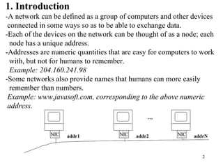
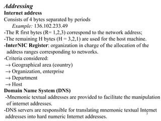
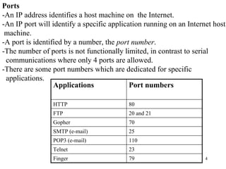
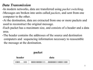
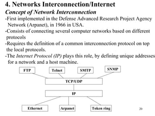
1. The document discusses basic networking concepts including protocols, protocol layers, and network interconnection. It provides details on network addressing, the Domain Name System, and port numbers.
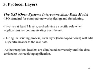
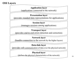
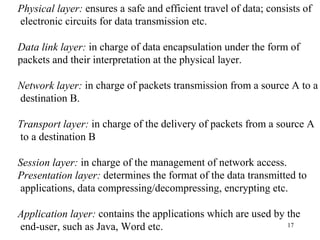
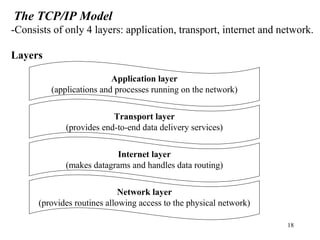
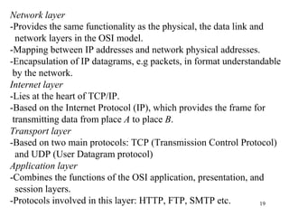
2. Key protocol layers are examined, including the OSI 7-layer model and the TCP/IP 4-layer model. The roles and functions of each layer are defined.
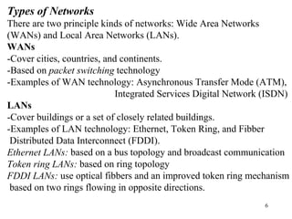
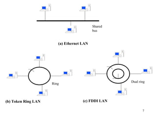
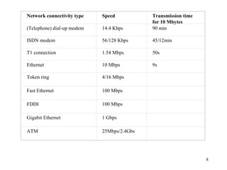
3. Types of networks like WANs, LANs, Ethernet, Token Ring, and FDDI are introduced along with examples of interconnection devices like bridges, routers, and gateways.