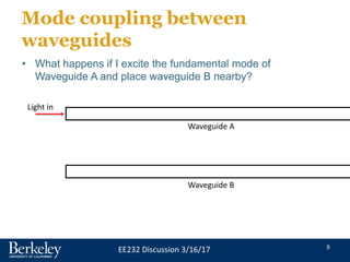
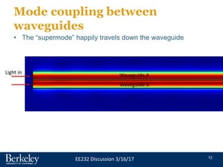
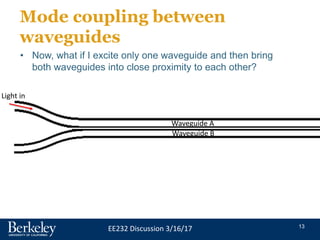
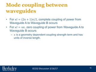
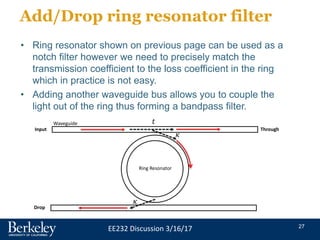
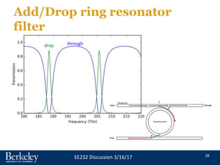
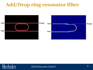
1
EE232 Discussion 3/16/17
Single wavelength / channel
optical communication
• The simplest optical communication scheme is single
wavelength / channel communication.
• The light from a single laser (VCSEL, DFB laser, etc.) is
electrically-modulated and sent through a single or
multimode fiber.
• The light is detected at the other end of the fiber and
converted back into electrical signal.
Tx
Optical fiber
λ1 Rx
Modulator
Electrical signal in
Electrical signal
out
2
EE232 Discussion 3/16/17
Single wavelength / channel
optical communication
10GB/s transceiver
850nm VCSEL
Max Range ~300m
Short reach data center
applications
Source: Finisar
3
EE232 Discussion 3/16/17
Wavelength division
multiplexing (WDM)
Tx
Tx
Tx
Optical fiber
λ1
λ2
λN
λ1
λ2
λN
Rx
Rx
Rx
Optical multiplexer Optical demultiplexer
• Many wavelengths are sent down the same optical fiber
• Capacity is increased by N times, N = # wavelengths
4
EE232 Discussion 3/16/17
Wavelength division
multiplexing (WDM)
• The International Telecommunications Union (ITU) has
standardized the telecom wavelengths and spacing. The
C-band is commonly used for dense WDM (DWDM).
Source: Cisco
5
EE232 Discussion 3/16/17
Attenuation and dispersion in
silica fibers
1300 nm is minimum dispersion point
1550 nm is minimum attenuation point
Source: photonicswiki.org
6
EE232 Discussion 3/16/17
Wavelength division
multiplexing (WDM)
Tx
Tx
Tx
Optical fiber
Rx
Rx
Rx
Optical multiplexer Optical demultiplexer
• What is inside the box?
λ1
λ2
λN
λ1
λ2
λN
7
EE232 Discussion 3/16/17
Silicon photonics
• Silicon photonics has emerged recently as a new
technology for photonic communication.
• Pros:
– Large index contrast  reduced size of optical components
– Leverage existing silicon infrastructure and expertise
– Photonics and electronics can coexist (in principle)
• Cons:
– Silicon is a “dark” material
– Difficulty in coupling light
– Large thermo-optic effect
8
EE232 Discussion 3/16/17
Silicon photonics
• For the next three class periods we will discuss strategies
to demodulate and modulate optical signals
• We will primarily focus on ring resonator based designs
although by no means the only way to multiplex or
demultiplex light.
• First, we need to discuss one important passive optical
component called the directional coupler.
9
EE232 Discussion 3/16/17
Mode coupling between
waveguides
• What happens if I excite the fundamental mode of
Waveguide A and place waveguide B nearby?
Waveguide A
Waveguide B
Light in
10
EE232 Discussion 3/16/17
Mode coupling between
waveguides
• The mode in Waveguide A happily travels down the
waveguide and does not “feel” the effect of Waveguide B
since it is too far away
Light in
11
EE232 Discussion 3/16/17
• Now, what if waveguide A and waveguide B are placed
right next to each other. The fundamental modes of each
waveguide are coupled and will form a “supermode”.
• What if we excite the supermode?
Waveguide A
Waveguide B
Light in
Mode coupling between
waveguides
12
EE232 Discussion 3/16/17
Mode coupling between
waveguides
• The “supermode” happily travels down the waveguide
Light in
Waveguide A
Waveguide B
13
EE232 Discussion 3/16/17
Mode coupling between
waveguides
• Now, what if I excite only one waveguide and then bring
both waveguides into close proximity to each other?
Light in
Waveguide A
Waveguide B
14
EE232 Discussion 3/16/17
Mode coupling between
waveguides
• Energy periodically sloshes back and forth between both
waveguides.
Waveguide A
Waveguide B
15
EE232 Discussion 3/16/17
Mode coupling between
waveguides
Power in Waveguide A Power in Waveguide B
16
EE232 Discussion 3/16/17
Mode coupling between
waveguides
• For 𝜅𝑙 = 2𝑛 + 1 𝜋/2, complete coupling of power from
Waveguide A to Waveguide B occurs
• For 𝜅𝑙 = 𝑛𝜋, zero coupling of power from Waveguide A to
Waveguide B occurs
– 𝜅 is a geometry dependent coupling strength term and has
units of inverse length.
17
EE232 Discussion 3/16/17
Mode coupling: Mechanical
analogy
• This “sloshing” of energy back and forth between
waveguides seems odd but is also observed between
other coupled systems including two coupled mechanical
pendulums.
• Coupled Pendulum-CjJVBvDNxcE.mkv
• (https://www.youtube.com/watch?v=CjJVBvDNxcE)
18
EE232 Discussion 3/16/17
Coupled modes as a quantum
two-level system
• H0 is the energy in an individual mode
• H1 is the overlap energy of the two modes
(“supermodes”)
E-fields in phase
Constructive
interference
E-fields out of phase
Destructive
interference
19
EE232 Discussion 3/16/17
Coupled modes as a quantum
two-level system
• H0 is the energy in an individual mode
• H1 is the overlap energy of the two modes
(“supermodes”)
For more rigorous E&M treatment
See Chuang 8.2
Oscillation between the two waveguides
Start in one waveguide
E-fields in phase
Constructive
interference
E-fields out of phase
Destructive
interference
20
EE232 Discussion 3/16/17
Ring resonator
• Light traveling down waveguide can couple to resonant
mode within the ring resonator
• Resonance wavelength occurs when light accumulates a
phase shift of 2𝜋 when traveling around the ring:
Waveguide
Ring Resonator
𝑡
𝜅
𝜅*
𝑡*
𝑎1 𝑏1
𝑎2 𝑏2
21
EE232 Discussion 3/16/17
Ring resonator
Waveguide
Ring Resonator
𝑡
𝜅
𝜅*
𝑡*
𝑎1 𝑏1
𝑎2 𝑏2
Power conservation:
𝑡∗𝑡 − 𝜅∗𝜅 = 1 U
Proof:
22
EE232 Discussion 3/16/17
Ring resonator
Waveguide
Ring Resonator
𝑡
𝜅
𝜅*
𝑡*
𝑎1 𝑏1
𝑎2 𝑏2
Power conservation:
𝑡∗
𝑡 − 𝜅∗
𝜅 = 1 𝑎2 = 𝑏2𝑒𝑖𝜃𝑒−
𝛼
2𝐿
𝑏1
𝑎1
=
𝑡 − 𝑎𝑒𝑖𝜃
1 − 𝑎𝑡𝑒𝑖𝜃
=>
𝑎 = 𝑒−
𝛼
2𝐿
Define
Circulation condition:
𝜃: phase change in ring (loss in ring)
23
EE232 Discussion 3/16/17
Power transmission
𝑎 = 𝑡
(critical coupling)
𝑎 = 1
(no waveguide loss)
𝑇 =
𝑡 − 𝑎𝑒𝑗𝜃
1 − 𝑎𝑡𝑒𝑗𝜃
2
𝜃: phase change in
ring
𝑎 = 𝑒−𝛼𝐿/2
𝑙𝑜𝑠𝑠 𝑖𝑛 𝑟𝑖𝑛𝑔
𝐿: ring length
24
EE232 Discussion 3/16/17
Ring resonator example
• Hewlett Packard Enterprise - Silicon Microring
Resonators-jdAYo5bM01k.mp4
• (https://www.youtube.com/watch?v=jdAYo5bM01k)
25
EE232 Discussion 3/16/17
Ring resonator all-pass filter
• Ring resonator with low waveguide loss (𝑎~1) can be
used an all-pass filter with 𝜋 phase delay
• What use do we have for this? Large change in phase at
resonance introduces group delay  optical buffer,
dispersion compensation, delay for Mach-Zehnder
interferometer.
26
EE232 Discussion 3/16/17
Ring resonator all-pass filter
𝜏
Light in Light out
Mach-Zehnder interferometer (MZI)
Destructive interference at output if
delay stage introduces 𝜋 phase shift.
Traditional delay stage incorporates
non-linear medium which will have
refractive index change with applied
voltage. Delay stage length may need to be
millimeters long to get 𝜋 phase shift.
Light in Light out
Mach-Zehnder interferometer (MZI)
w/ ring resonator delay stage
Compact delay stage
27
EE232 Discussion 3/16/17
Add/Drop ring resonator filter
• Ring resonator shown on previous page can be used as a
notch filter however we need to precisely match the
transmission coefficient to the loss coefficient in the ring
which in practice is not easy.
• Adding another waveguide bus allows you to couple the
light out of the ring thus forming a bandpass filter.
Waveguide
Ring Resonator
𝑡
𝜅
𝜅
Input Through
Drop
28
EE232 Discussion 3/16/17
Add/Drop ring resonator
filter
drop through
29
EE232 Discussion 3/16/17
Add/Drop ring resonator filter
Input Through
Drop
Input Through
Drop
30
EE232 Discussion 3/16/17
WDM demultiplexing
• Basic implementation
𝜆1, 𝜆2, 𝜆3, 𝜆4
(in)
𝜆1
𝜆2
𝜆3
𝜆4
Detector Detector Detector Detector
31
EE232 Discussion 3/16/17
Comments on ring resonators
• Higher order filters can be constructed by adding several
rings in series.
• Resonant frequency of ring resonator is very sensitive to
process variation (variation in effective index) and
temperature.
• Practical ring resonators for use in a real-world
environment need integrated temperature control to
stabilize and adjust resonance frequency.
Optics Express Vol. 23, Issue 16, pp. 21527-21540 (2015)
32
EE232 Discussion 3/16/17
Modulation with ring
resonators
• Resonance frequency sensitivity to effective index can be
exploited for modulation of light
• The index of refraction of silicon can be modified by
injecting (or removing) free carriers by applied bias
Nature 435, 325-327 (19 May 2005)
33
EE232 Discussion 3/16/17
Modulation with ring
resonators
Nature 528, 534–538 (24 December 2015)
34
EE232 Discussion 3/16/17
Next week
• We will discuss modulation with ring resonators and begin
designing a modulator based on change in refractive
index of silicon with applied bias.
• Please download and install Lumerical DEVICE (device
simulator) if you have not already done so.

Discussion 8 - Directional coupler.pptx

  • 1.
    1 EE232 Discussion 3/16/17 Singlewavelength / channel optical communication • The simplest optical communication scheme is single wavelength / channel communication. • The light from a single laser (VCSEL, DFB laser, etc.) is electrically-modulated and sent through a single or multimode fiber. • The light is detected at the other end of the fiber and converted back into electrical signal. Tx Optical fiber λ1 Rx Modulator Electrical signal in Electrical signal out
  • 2.
    2 EE232 Discussion 3/16/17 Singlewavelength / channel optical communication 10GB/s transceiver 850nm VCSEL Max Range ~300m Short reach data center applications Source: Finisar
  • 3.
    3 EE232 Discussion 3/16/17 Wavelengthdivision multiplexing (WDM) Tx Tx Tx Optical fiber λ1 λ2 λN λ1 λ2 λN Rx Rx Rx Optical multiplexer Optical demultiplexer • Many wavelengths are sent down the same optical fiber • Capacity is increased by N times, N = # wavelengths
  • 4.
    4 EE232 Discussion 3/16/17 Wavelengthdivision multiplexing (WDM) • The International Telecommunications Union (ITU) has standardized the telecom wavelengths and spacing. The C-band is commonly used for dense WDM (DWDM). Source: Cisco
  • 5.
    5 EE232 Discussion 3/16/17 Attenuationand dispersion in silica fibers 1300 nm is minimum dispersion point 1550 nm is minimum attenuation point Source: photonicswiki.org
  • 6.
    6 EE232 Discussion 3/16/17 Wavelengthdivision multiplexing (WDM) Tx Tx Tx Optical fiber Rx Rx Rx Optical multiplexer Optical demultiplexer • What is inside the box? λ1 λ2 λN λ1 λ2 λN
  • 7.
    7 EE232 Discussion 3/16/17 Siliconphotonics • Silicon photonics has emerged recently as a new technology for photonic communication. • Pros: – Large index contrast  reduced size of optical components – Leverage existing silicon infrastructure and expertise – Photonics and electronics can coexist (in principle) • Cons: – Silicon is a “dark” material – Difficulty in coupling light – Large thermo-optic effect
  • 8.
    8 EE232 Discussion 3/16/17 Siliconphotonics • For the next three class periods we will discuss strategies to demodulate and modulate optical signals • We will primarily focus on ring resonator based designs although by no means the only way to multiplex or demultiplex light. • First, we need to discuss one important passive optical component called the directional coupler.
  • 9.
    9 EE232 Discussion 3/16/17 Modecoupling between waveguides • What happens if I excite the fundamental mode of Waveguide A and place waveguide B nearby? Waveguide A Waveguide B Light in
  • 10.
    10 EE232 Discussion 3/16/17 Modecoupling between waveguides • The mode in Waveguide A happily travels down the waveguide and does not “feel” the effect of Waveguide B since it is too far away Light in
  • 11.
    11 EE232 Discussion 3/16/17 •Now, what if waveguide A and waveguide B are placed right next to each other. The fundamental modes of each waveguide are coupled and will form a “supermode”. • What if we excite the supermode? Waveguide A Waveguide B Light in Mode coupling between waveguides
  • 12.
    12 EE232 Discussion 3/16/17 Modecoupling between waveguides • The “supermode” happily travels down the waveguide Light in Waveguide A Waveguide B
  • 13.
    13 EE232 Discussion 3/16/17 Modecoupling between waveguides • Now, what if I excite only one waveguide and then bring both waveguides into close proximity to each other? Light in Waveguide A Waveguide B
  • 14.
    14 EE232 Discussion 3/16/17 Modecoupling between waveguides • Energy periodically sloshes back and forth between both waveguides. Waveguide A Waveguide B
  • 15.
    15 EE232 Discussion 3/16/17 Modecoupling between waveguides Power in Waveguide A Power in Waveguide B
  • 16.
    16 EE232 Discussion 3/16/17 Modecoupling between waveguides • For 𝜅𝑙 = 2𝑛 + 1 𝜋/2, complete coupling of power from Waveguide A to Waveguide B occurs • For 𝜅𝑙 = 𝑛𝜋, zero coupling of power from Waveguide A to Waveguide B occurs – 𝜅 is a geometry dependent coupling strength term and has units of inverse length.
  • 17.
    17 EE232 Discussion 3/16/17 Modecoupling: Mechanical analogy • This “sloshing” of energy back and forth between waveguides seems odd but is also observed between other coupled systems including two coupled mechanical pendulums. • Coupled Pendulum-CjJVBvDNxcE.mkv • (https://www.youtube.com/watch?v=CjJVBvDNxcE)
  • 18.
    18 EE232 Discussion 3/16/17 Coupledmodes as a quantum two-level system • H0 is the energy in an individual mode • H1 is the overlap energy of the two modes (“supermodes”) E-fields in phase Constructive interference E-fields out of phase Destructive interference
  • 19.
    19 EE232 Discussion 3/16/17 Coupledmodes as a quantum two-level system • H0 is the energy in an individual mode • H1 is the overlap energy of the two modes (“supermodes”) For more rigorous E&M treatment See Chuang 8.2 Oscillation between the two waveguides Start in one waveguide E-fields in phase Constructive interference E-fields out of phase Destructive interference
  • 20.
    20 EE232 Discussion 3/16/17 Ringresonator • Light traveling down waveguide can couple to resonant mode within the ring resonator • Resonance wavelength occurs when light accumulates a phase shift of 2𝜋 when traveling around the ring: Waveguide Ring Resonator 𝑡 𝜅 𝜅* 𝑡* 𝑎1 𝑏1 𝑎2 𝑏2
  • 21.
    21 EE232 Discussion 3/16/17 Ringresonator Waveguide Ring Resonator 𝑡 𝜅 𝜅* 𝑡* 𝑎1 𝑏1 𝑎2 𝑏2 Power conservation: 𝑡∗𝑡 − 𝜅∗𝜅 = 1 U Proof:
  • 22.
    22 EE232 Discussion 3/16/17 Ringresonator Waveguide Ring Resonator 𝑡 𝜅 𝜅* 𝑡* 𝑎1 𝑏1 𝑎2 𝑏2 Power conservation: 𝑡∗ 𝑡 − 𝜅∗ 𝜅 = 1 𝑎2 = 𝑏2𝑒𝑖𝜃𝑒− 𝛼 2𝐿 𝑏1 𝑎1 = 𝑡 − 𝑎𝑒𝑖𝜃 1 − 𝑎𝑡𝑒𝑖𝜃 => 𝑎 = 𝑒− 𝛼 2𝐿 Define Circulation condition: 𝜃: phase change in ring (loss in ring)
  • 23.
    23 EE232 Discussion 3/16/17 Powertransmission 𝑎 = 𝑡 (critical coupling) 𝑎 = 1 (no waveguide loss) 𝑇 = 𝑡 − 𝑎𝑒𝑗𝜃 1 − 𝑎𝑡𝑒𝑗𝜃 2 𝜃: phase change in ring 𝑎 = 𝑒−𝛼𝐿/2 𝑙𝑜𝑠𝑠 𝑖𝑛 𝑟𝑖𝑛𝑔 𝐿: ring length
  • 24.
    24 EE232 Discussion 3/16/17 Ringresonator example • Hewlett Packard Enterprise - Silicon Microring Resonators-jdAYo5bM01k.mp4 • (https://www.youtube.com/watch?v=jdAYo5bM01k)
  • 25.
    25 EE232 Discussion 3/16/17 Ringresonator all-pass filter • Ring resonator with low waveguide loss (𝑎~1) can be used an all-pass filter with 𝜋 phase delay • What use do we have for this? Large change in phase at resonance introduces group delay  optical buffer, dispersion compensation, delay for Mach-Zehnder interferometer.
  • 26.
    26 EE232 Discussion 3/16/17 Ringresonator all-pass filter 𝜏 Light in Light out Mach-Zehnder interferometer (MZI) Destructive interference at output if delay stage introduces 𝜋 phase shift. Traditional delay stage incorporates non-linear medium which will have refractive index change with applied voltage. Delay stage length may need to be millimeters long to get 𝜋 phase shift. Light in Light out Mach-Zehnder interferometer (MZI) w/ ring resonator delay stage Compact delay stage
  • 27.
    27 EE232 Discussion 3/16/17 Add/Dropring resonator filter • Ring resonator shown on previous page can be used as a notch filter however we need to precisely match the transmission coefficient to the loss coefficient in the ring which in practice is not easy. • Adding another waveguide bus allows you to couple the light out of the ring thus forming a bandpass filter. Waveguide Ring Resonator 𝑡 𝜅 𝜅 Input Through Drop
  • 28.
    28 EE232 Discussion 3/16/17 Add/Dropring resonator filter drop through
  • 29.
    29 EE232 Discussion 3/16/17 Add/Dropring resonator filter Input Through Drop Input Through Drop
  • 30.
    30 EE232 Discussion 3/16/17 WDMdemultiplexing • Basic implementation 𝜆1, 𝜆2, 𝜆3, 𝜆4 (in) 𝜆1 𝜆2 𝜆3 𝜆4 Detector Detector Detector Detector
  • 31.
    31 EE232 Discussion 3/16/17 Commentson ring resonators • Higher order filters can be constructed by adding several rings in series. • Resonant frequency of ring resonator is very sensitive to process variation (variation in effective index) and temperature. • Practical ring resonators for use in a real-world environment need integrated temperature control to stabilize and adjust resonance frequency. Optics Express Vol. 23, Issue 16, pp. 21527-21540 (2015)
  • 32.
    32 EE232 Discussion 3/16/17 Modulationwith ring resonators • Resonance frequency sensitivity to effective index can be exploited for modulation of light • The index of refraction of silicon can be modified by injecting (or removing) free carriers by applied bias Nature 435, 325-327 (19 May 2005)
  • 33.
    33 EE232 Discussion 3/16/17 Modulationwith ring resonators Nature 528, 534–538 (24 December 2015)
  • 34.
    34 EE232 Discussion 3/16/17 Nextweek • We will discuss modulation with ring resonators and begin designing a modulator based on change in refractive index of silicon with applied bias. • Please download and install Lumerical DEVICE (device simulator) if you have not already done so.

Editor's Notes

  • #19 H=\left( \begin{matrix} H_0 && H_1 \\ H_1 && H_0\end{matrix}\right) \Psi_1 = \left(\begin{matrix} 1 \\ 1\end{matrix}\right), \Psi_2 = \left(\begin{matrix} 1 \\ -1\end{matrix}\right) \\ \\ E_1=H_0+H_1, \; E_2=H_0-H_1
  • #20 H=\left( \begin{matrix} H_0 && H_1 \\ H_1 && H_0\end{matrix}\right) \Psi_1 = \left(\begin{matrix} 1 \\ 1\end{matrix}\right), \Psi_2 = \left(\begin{matrix} 1 \\ -1\end{matrix}\right) \\ \\ E_1=H_0+H_1, \; E_2=H_0-H_1 \Psi(0)=\left(\begin{matrix} 1 \\ 0 \end{matrix}\right) = \Psi_1+\Psi_2 \\ \\ \begin{align*} \Psi(t)&=\Psi_1e^{-i(H_0+H_1)t/\hbar}+\Psi_2 e^{-i(H_0-H_1)t/\hbar}\\ &=e^{-iH_0t/\hbar}\left(\begin{matrix} \cos{H_1 t/\hbar} \\ i \sin{H_1 t/\hbar}\end{matrix}\right) \end{align*}