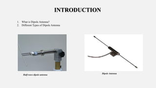
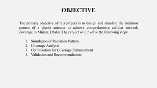
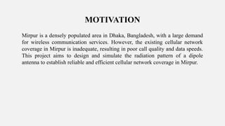
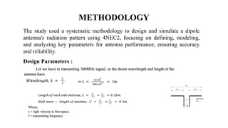
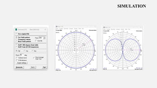
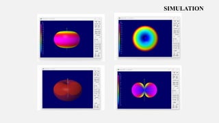
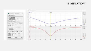
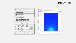
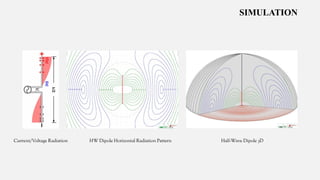
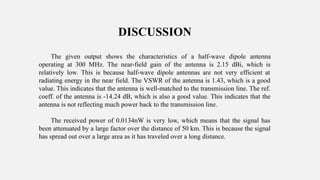
Welcome to our
Presentation
Course Code : EEE 364
Course Title : Microwave Engineering Lab
Faculty of Engineering & Applied Science
Department of Electrical & Electronic Engineering
Project Name
Design and Simulate the Radiation Pattern of Dipole Antenna also
Establishing the Coverage area of Mirpur.
SUBMITTED BY:
Group : 01
Department of EEE(BUBT)
SL. Name ID Intake Section
01 Md. Sazzad Hossain 19203208028 30 01
02 Udoy Chandra Das 19203208003 30 01
04 Sharmin Asha 19203208006 30 01
03 Md. Mahedi Hasan 19203208008 30 01
05 Md. Shaon Ahamed 19203208014 30 01
06 Md. Nazmul Hossain 19203208024 30 01
07 Bikash Kumar Pramanik 19203208025 30 01
SUBMITTED TO:
Dr. Md. Shamsul Arefin
Assistant Professor,
Department of Electrical & Electronic Engineering
Bangladesh University of Business & Technology
Outline of this project
1. Introduction
2. Objective
3. Motivation
4. Background
5. Methodology
6. Simulation
7. Results
8. Discussion
9. Limitation
10. Conclusion
7
INTRODUCTION
1. What is Dipole Antenna?
2. Different Types of Dipole Antenna
Dipole Antenna
Half-wave dipole antenna
INTRODUCTION
Animation of a transmitting half wave dipole showing the
voltage V(x) (red) and current I(x)(blue,)
Half-wave dipole antenna
INTRODUCTION
Dipole antenna transmitting and receiving section
Dipole transmitting antenna
Dipole receiving antenna
OBJECTIVE
The primary objective of this project is to design and simulate the radiation
pattern of a dipole antenna to achieve comprehensive cellular network
coverage in Mirpur, Dhaka. The project will involve the following steps:
1. Simulation of Radiation Pattern
2. Coverage Analysis
3. Optimization for Coverage Enhancement
4. Validation and Recommendations
Mirpur is a densely populated area in Dhaka, Bangladesh, with a large demand
for wireless communication services. However, the existing cellular network
coverage in Mirpur is inadequate, resulting in poor call quality and data speeds.
This project aims to design and simulate the radiation pattern of a dipole
antenna to establish reliable and efficient cellular network coverage in Mirpur.
MOTIVATION
BACKGROUND
Mirpur, a densely populated Dhaka region, faces challenges in wireless
communication due to insufficient infrastructure, leading to poor call quality,
slow data rates, and frequent congestion. Factors like population density,
topography, and infrastructural restrictions exacerbate the issue, affecting
communication, education, and work opportunities.
The study used a systematic methodology to design and simulate a dipole
antenna's radiation pattern using 4NEC2, focusing on defining, modeling,
and analyzing key parameters for antenna performance, ensuring accuracy
and reliability.
METHODOLOGY
Design Parameters :
Here is the list of required components of this projects:
1. Computer &
2. Software 4NEC2.
EQUIPMENT’S
SIMULATION
Main window
SIMULATION
Geometry view of dipole antenna
Axis : 0.5 mtr
SIMULATION
Geometry window
SIMULATION
Source/Load
SIMULATION
Frequency/Ground
SIMULATION
SIMULATION
SIMULATION
SIMULATION
24
HW Dipole Horizontal Radiation Pattern Half-Wave Dipole 3D
SIMULATION
Current/Voltage Radiation
RESULT
RESULT
Friis transmission equation : (02) Effective aperture equation : (01)
DISCUSSION
The given output shows the characteristics of a half-wave dipole antenna
operating at 300 MHz. The near-field gain of the antenna is 2.15 dBi, which is
relatively low. This is because half-wave dipole antennas are not very efficient at
radiating energy in the near field. The VSWR of the antenna is 1.43, which is a good
value. This indicates that the antenna is well-matched to the transmission line. The ref.
coeff. of the antenna is -14.24 dB, which is also a good value. This indicates that the
antenna is not reflecting much power back to the transmission line.
The received power of 0.0134nW is very low, which means that the signal has
been attenuated by a large factor over the distance of 50 km. This is because the signal
has spread out over a large area as it has traveled over a long distance.
Limitation
Limitations of the project redesign and simulation for radiation pattern analysis and coverage
establishment in the Mirpur area using a dipole antenna include:
1. Simulation Accuracy
2. Environmental Factors
3. Antenna Characteristics
4. Frequency Considerations
5. Interference and Obstructions
To address these limitations, a comprehensive validation process involving field
measurements, empirical data collection, and adjustments based on real-world conditions
should be incorporated. Additionally, ongoing monitoring and adjustments to the network
design can enhance the accuracy of coverage predictions in practical deployments.
CONCLUSION
The half-wave dipole antenna at 300 MHz has a low near-field gain 2.15dBi,
indicating inefficiency in radiating energy in close proximity. However, its
VSWR of 1.43 and ref. coeff. of -14.24 dB suggest a good match with the
transmission line and minimal power reflection. The received power of
0.0134nW is low due to signal dispersion over a large area during transmission.
To enhance the received power, consider using a directional antenna with higher
gain, reducing the distance between the transmitter and receiver, or using a
repeater to amplify the signal. In summary, the antenna's performance is
characterized by low near-field gain, favorable transmission line matching, and
minimal power reflection.
ANY QUESTION?
THANK YOU EVERYONE

Dipole antenna radiation pattern.pdf

  • 1.
  • 2.
    Course Code :EEE 364 Course Title : Microwave Engineering Lab Faculty of Engineering & Applied Science Department of Electrical & Electronic Engineering
  • 3.
    Project Name Design andSimulate the Radiation Pattern of Dipole Antenna also Establishing the Coverage area of Mirpur.
  • 4.
    SUBMITTED BY: Group :01 Department of EEE(BUBT) SL. Name ID Intake Section 01 Md. Sazzad Hossain 19203208028 30 01 02 Udoy Chandra Das 19203208003 30 01 04 Sharmin Asha 19203208006 30 01 03 Md. Mahedi Hasan 19203208008 30 01 05 Md. Shaon Ahamed 19203208014 30 01 06 Md. Nazmul Hossain 19203208024 30 01 07 Bikash Kumar Pramanik 19203208025 30 01
  • 5.
    SUBMITTED TO: Dr. Md.Shamsul Arefin Assistant Professor, Department of Electrical & Electronic Engineering Bangladesh University of Business & Technology
  • 6.
    Outline of thisproject 1. Introduction 2. Objective 3. Motivation 4. Background 5. Methodology 6. Simulation 7. Results 8. Discussion 9. Limitation 10. Conclusion
  • 7.
    7 INTRODUCTION 1. What isDipole Antenna? 2. Different Types of Dipole Antenna Dipole Antenna Half-wave dipole antenna
  • 8.
    INTRODUCTION Animation of atransmitting half wave dipole showing the voltage V(x) (red) and current I(x)(blue,) Half-wave dipole antenna Half-wave dipole antenna
  • 9.
    INTRODUCTION Dipole antenna transmittingand receiving section Dipole transmitting antenna Dipole receiving antenna
  • 10.
    OBJECTIVE The primary objectiveof this project is to design and simulate the radiation pattern of a dipole antenna to achieve comprehensive cellular network coverage in Mirpur, Dhaka. The project will involve the following steps: 1. Simulation of Radiation Pattern 2. Coverage Analysis 3. Optimization for Coverage Enhancement 4. Validation and Recommendations
  • 11.
    Mirpur is adensely populated area in Dhaka, Bangladesh, with a large demand for wireless communication services. However, the existing cellular network coverage in Mirpur is inadequate, resulting in poor call quality and data speeds. This project aims to design and simulate the radiation pattern of a dipole antenna to establish reliable and efficient cellular network coverage in Mirpur. MOTIVATION
  • 12.
    BACKGROUND Mirpur, a denselypopulated Dhaka region, faces challenges in wireless communication due to insufficient infrastructure, leading to poor call quality, slow data rates, and frequent congestion. Factors like population density, topography, and infrastructural restrictions exacerbate the issue, affecting communication, education, and work opportunities.
  • 13.
    The study useda systematic methodology to design and simulate a dipole antenna's radiation pattern using 4NEC2, focusing on defining, modeling, and analyzing key parameters for antenna performance, ensuring accuracy and reliability. METHODOLOGY Design Parameters :
  • 14.
    Here is thelist of required components of this projects: 1. Computer & 2. Software 4NEC2. EQUIPMENT’S
  • 15.
  • 16.
    SIMULATION Geometry view ofdipole antenna Axis : 0.5 mtr
  • 17.
  • 18.
  • 19.
  • 20.
  • 21.
  • 22.
  • 23.
  • 24.
    24 HW Dipole HorizontalRadiation Pattern Half-Wave Dipole 3D SIMULATION Current/Voltage Radiation
  • 25.
  • 26.
    RESULT Friis transmission equation: (02) Effective aperture equation : (01)
  • 27.
    DISCUSSION The given outputshows the characteristics of a half-wave dipole antenna operating at 300 MHz. The near-field gain of the antenna is 2.15 dBi, which is relatively low. This is because half-wave dipole antennas are not very efficient at radiating energy in the near field. The VSWR of the antenna is 1.43, which is a good value. This indicates that the antenna is well-matched to the transmission line. The ref. coeff. of the antenna is -14.24 dB, which is also a good value. This indicates that the antenna is not reflecting much power back to the transmission line. The received power of 0.0134nW is very low, which means that the signal has been attenuated by a large factor over the distance of 50 km. This is because the signal has spread out over a large area as it has traveled over a long distance.
  • 28.
    Limitation Limitations of theproject redesign and simulation for radiation pattern analysis and coverage establishment in the Mirpur area using a dipole antenna include: 1. Simulation Accuracy 2. Environmental Factors 3. Antenna Characteristics 4. Frequency Considerations 5. Interference and Obstructions To address these limitations, a comprehensive validation process involving field measurements, empirical data collection, and adjustments based on real-world conditions should be incorporated. Additionally, ongoing monitoring and adjustments to the network design can enhance the accuracy of coverage predictions in practical deployments.
  • 29.
    CONCLUSION The half-wave dipoleantenna at 300 MHz has a low near-field gain 2.15dBi, indicating inefficiency in radiating energy in close proximity. However, its VSWR of 1.43 and ref. coeff. of -14.24 dB suggest a good match with the transmission line and minimal power reflection. The received power of 0.0134nW is low due to signal dispersion over a large area during transmission. To enhance the received power, consider using a directional antenna with higher gain, reducing the distance between the transmitter and receiver, or using a repeater to amplify the signal. In summary, the antenna's performance is characterized by low near-field gain, favorable transmission line matching, and minimal power reflection.
  • 30.
  • 31.