seven segment display program in embedded systems lab
1.
LAB-7 INTERFACING SEVENSEGMENT DISPLAY
8.1 Introduction
This laboratory studies the use of seven segment displays for various applications. Seven segment
displays are important display units in Electronics and widely used to display numbers from 0
to 9. It can also display some character alphabets like A,B,C,H,F,E etc. In this experiment, we
are going to learn how to interface a 7 segment display with 8051 microcontroller. We are using
P89V51RD2 microcontroller from 8051 series.
8.2 Objective
8.2.1 Educational
ˆ Learn the different types of seven segment display types.
ˆ Learn how the seven segment display, displays numbers as well as character alphabets.
ˆ Learn the hexadecimal code for displaying numbers as well as character alphabets on seven
segment display
8.2.2 Experimental
ˆ Understand how to interface seven segment displays with 8051 in trainer board using jumpers.
ˆ Understand the hardware connections of interfacing of seven segment displays with 8051
microcontroller.
ˆ Understand the usage of Keil IDE tool.
8.3 Prelab Preparation:
8.3.1 Reading
ˆ Understand the circuit diagram given in the background section of this Laboratory exercise.
ˆ Learn the program given in the background section of this Laboratory exercise.
8.3.2 Written
ˆ After coming to lab, student should write the experiment on the worksheets provided by the
teaching faculty on his/her own.
8.4 Pre lab viva Questions
1. Define switch bounce?
2. Define port in microcontroller.
3. Define interrupt in microcontroller?
45
2.
8.5 Equipment needed
8.5.1Hardware Requirements:
1. 8051 Development Board.
2. A serial 9 pin cable wired one to one from female connector to male connector.
3. PC with serial port.
4. 9V adaptor.
5. Connecting jumper and Connecting Wires.
8.5.2 Software Requirements:
1. Flash Magic tool.
2. Keil evaluation software.
3. Proteus 8 Professional.
8.6 Background
Before interfacing, we should learn about 7 segment display. It’s the simplest unit to display
numbers and characters. It just consists 8 LEDs, each LED used to illuminate one segment of
unit and the 8th LED used to illuminate DOT in 7 segment display. We can refer each segment
as a LINE, as we can see there are 7 lines in the unit, which are used to display a number/charac-
ter. We can refer each line/segment ”a,b,c,d,e,f,g” and for dot character we will use ”h”. There
are 10 pins, in which 8 pins are used to refer a,b,c,d,e,f,g and h/dp, the two middle pins are
common anode/cathode of all he LEDs. These common anode/cathode are internally shorted
so we need to connect only one COM pin.
There are two types of 7 segment displays: Common Anode and Common Cathode.
Common Anode: In this all the Negative terminals (cathode) of all the 8 LEDs are connected
together (see diagram below), named as COM. And all the positive terminals are left alone.
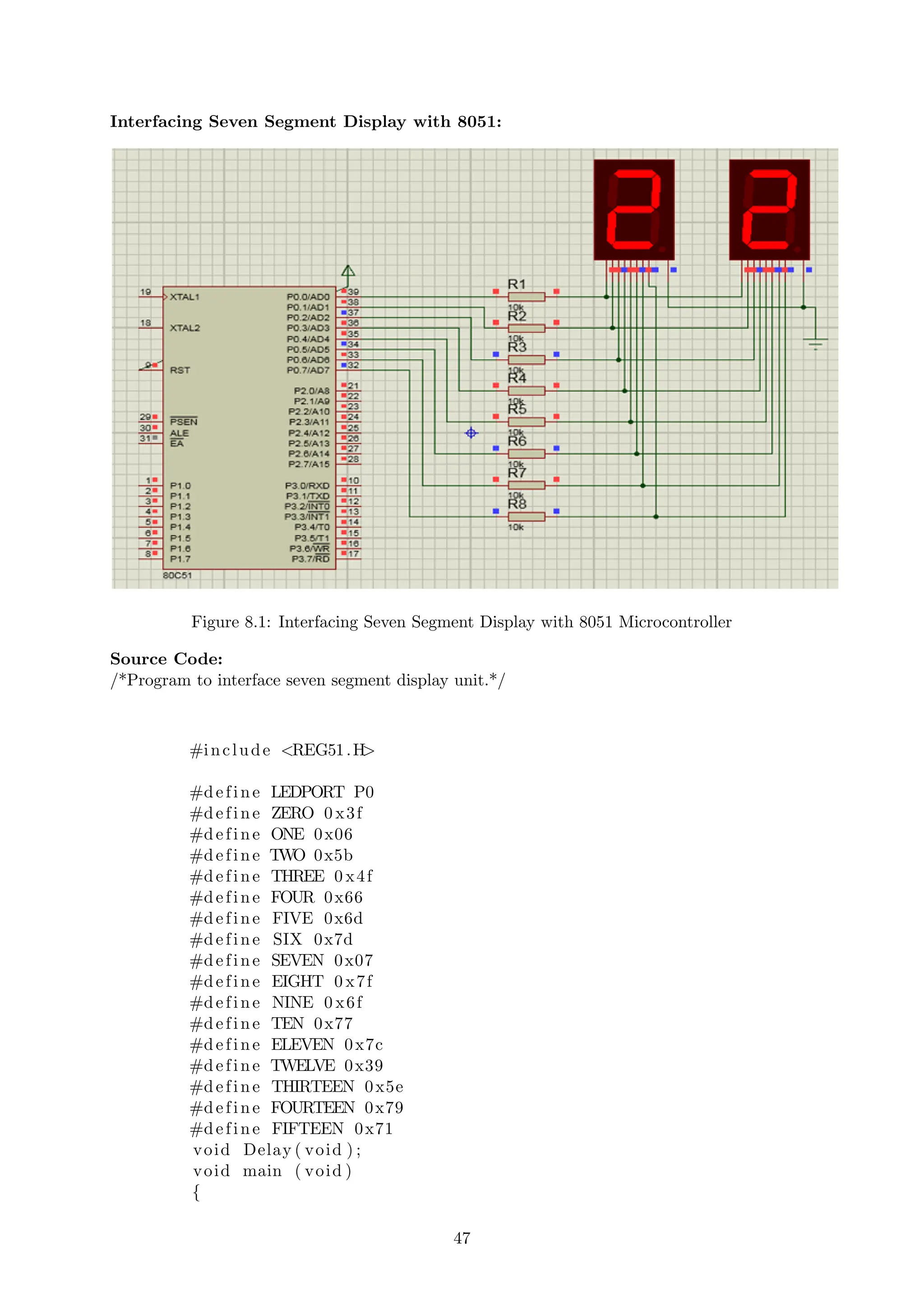
Common Cathode: In this all the positive terminals (Anodes) of all the 8 LEDs are connected
together, named as COM. And all the negative thermals are left alone. As shown below the
circuit diagram for interfacing 7 segment display with 8051 microcontroller, we have connected
a,b,c,d,e,f,g,h to pins 0.0 to 0.7 means we are connecting 7 segment to port 0 of microcontroller.
Now suppose we want to display 0, then we need to glow all the LEDs except LED which be-
longs to line “g”, so pins 0.0 to 0.6 should be at 1 (should be 1 to TURN ON the LED as per
positive logic) and pin 0.7 and 0.8 should be at 0 (should be 0 to TURN OFF the LED as per
positive logic). So the LEDs connected to pins 0.0 to 0.6 (a,b,c,d,e,f) will be ON and LEDs
connected to 0.7 and 0.8 (g and h) will be OFF, that will create a “0” in 7 segment. So we
need bit pattern 00111111 (Pin 8 is the highest bit so starting from P0.7 to P0.0), and the HEX
code for binary 00111111 is “3F”. Similarly we can calculate for all the digits. Here we should
note that we are keeping “dot/h” always OFF, so we need to give LOGIC “0” to it every time.
A table has been given below for all the numbers while using Common cathode 7 segment display.
46
3.
Interfacing Seven SegmentDisplay with 8051:
Figure 8.1: Interfacing Seven Segment Display with 8051 Microcontroller
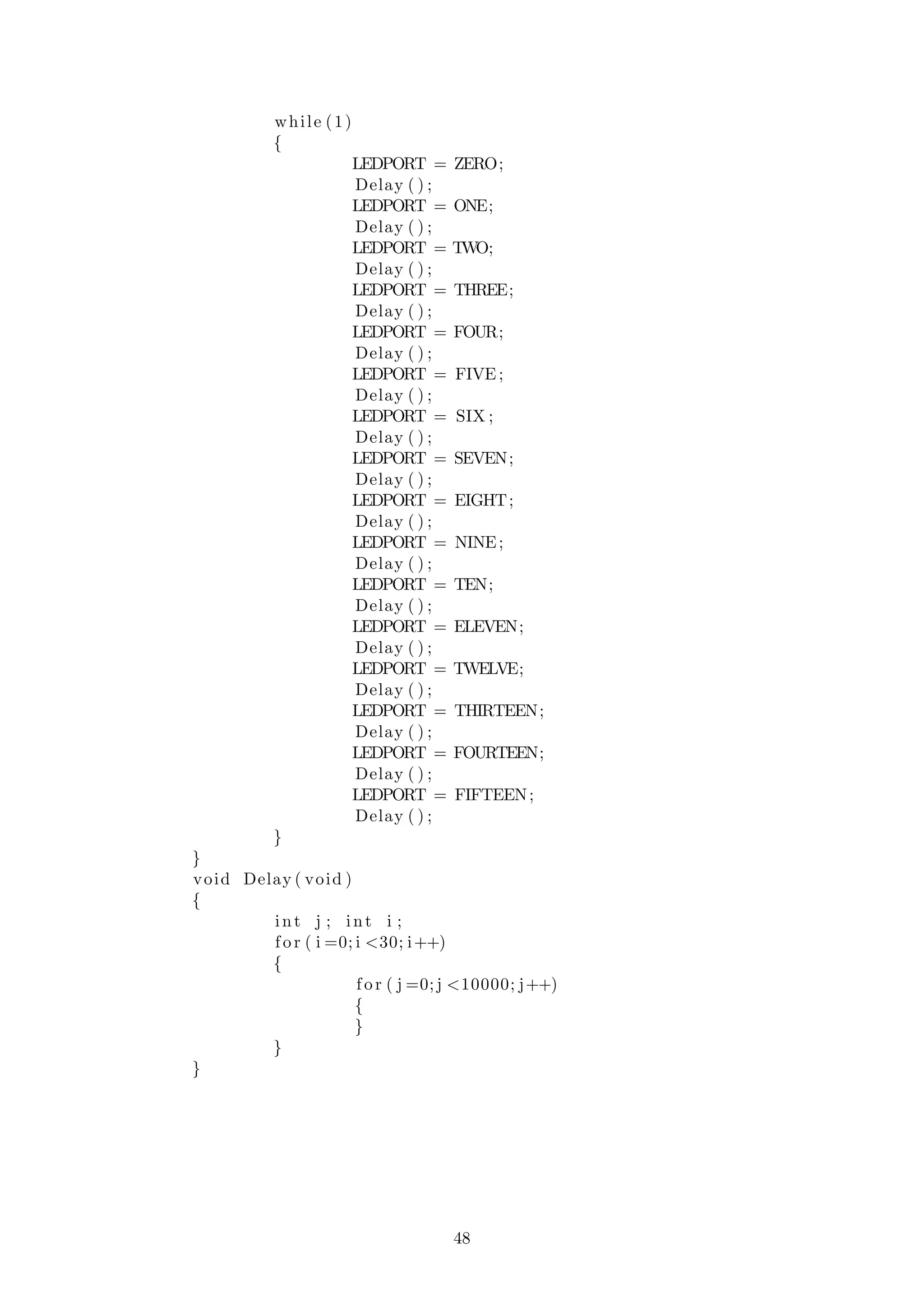
Source Code:
/*Program to interface seven segment display unit.*/
#include <REG51.H>
#define LEDPORT P0
#define ZERO 0 x3f
#define ONE 0x06
#define TWO 0x5b
#define THREE 0 x4f
#define FOUR 0x66
#define FIVE 0x6d
#define SIX 0x7d
#define SEVEN 0x07
#define EIGHT 0 x7f
#define NINE 0 x6f
#define TEN 0x77
#define ELEVEN 0x7c
#define TWELVE 0x39
#define THIRTEEN 0x5e
#define FOURTEEN 0x79
#define FIFTEEN 0x71
void Delay ( void ) ;
void main ( void )
{
47
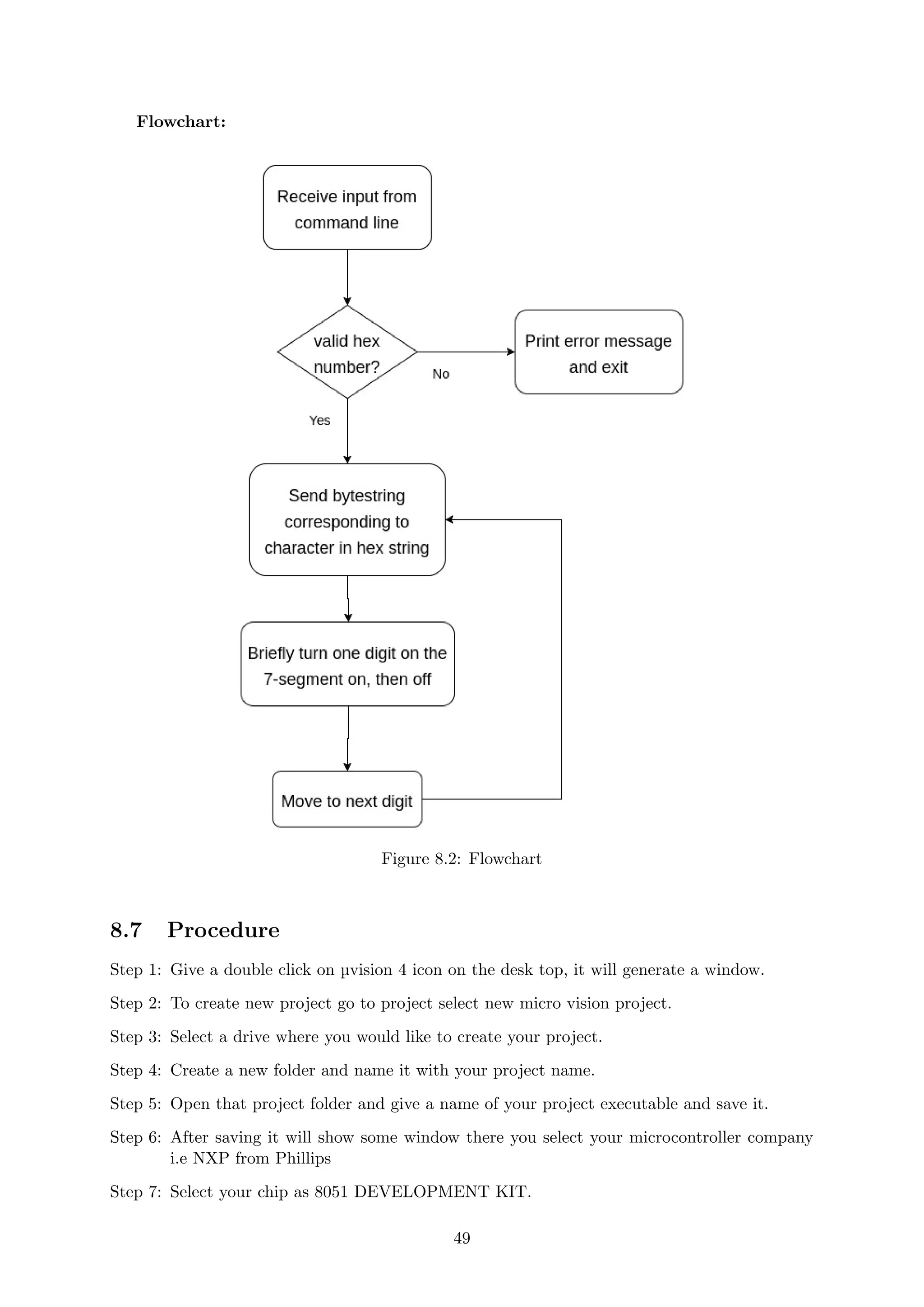
Flowchart:
Figure 8.2: Flowchart
8.7Procedure
Step 1: Give a double click on µvision 4 icon on the desk top, it will generate a window.
Step 2: To create new project go to project select new micro vision project.
Step 3: Select a drive where you would like to create your project.
Step 4: Create a new folder and name it with your project name.
Step 5: Open that project folder and give a name of your project executable and save it.
Step 6: After saving it will show some window there you select your microcontroller company
i.e NXP from Phillips
Step 7: Select your chip as 8051 DEVELOPMENT KIT.
49
6.
Step 8: Afterselecting chip click on OK then it will display some window asking to add STARTUP
. Select YES.
Step 9: A target is created and startup is added to your project target.
Step 10: To write your project code select a new from menu bar.
Step 11: It will display some text editor, to save that select SAVE option from menu bar.
Step 12: By giving a name with extension .c and save it
Step 13: To add our c to target give a right click on Source Group, choose “ADD s to Group”
option.
Step 14: It will display some window there select you have to add and click on ADD option.
Step 15: It will be added to our target and it shows in the project window.
Step 16: Now give a right click on target in the project window and select “Options for Target”.
Step 17: It will show some window, in that go to output option and choose Create Hex option
by Selecting that box.
Step 18: : In the same window go to Linker option and choose Use Memory Layout from Target
Dialog by Selecting the box, and click OK.
Step 19: Now to compile your project go to Project select Build Target option or press F7.
Step 20: Check the concern block of output and observe the results.
8.8 Precautions
1. Use the updated version of the Keil IDE tool.
2. Make sure correct power supply is given to the kit/Equipment.
3. Turn off the 8051 trainer board while giving hardware connections between Hexa Keypad
and port pins of 8051 microcontroller.
4. Observe the results carefully.
8.9 Result
50