The document provides information on digital and analog signals, different number systems used in computing including binary, octal, decimal and hexadecimal. It explains:
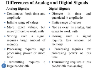
- Digital signals have discrete amplitude values of 0V and 5V, while analog signals can have any amplitude value.
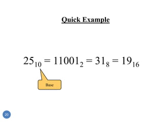
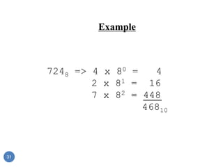
- Number systems like binary, octal and hexadecimal are used in computing to represent values using discrete digits. Conversion between number systems involves place value weighting.
- Binary uses two digits 0 and 1. Octal uses eight digits 0-7. Hexadecimal uses sixteen digits and letters 0-9 and A-F. Conversion between number systems and decimal is done by successive multiplication or division.
Digital electronics(EC8392) unit- 1-Sesha Vidhya S/ ASP/ECE/RMKCETSeshaVidhyaS
Number systems, Number conversion,Logic Gates,Boolean Theorem and Laws,Boolean Simplification,NAND,NOR Implementation,K-MAP simplification and Tabulation Method
Digital electronics(EC8392) unit- 1-Sesha Vidhya S/ ASP/ECE/RMKCETSeshaVidhyaS
Number systems, Number conversion,Logic Gates,Boolean Theorem and Laws,Boolean Simplification,NAND,NOR Implementation,K-MAP simplification and Tabulation Method
Contents:
1.What is number system?
2.Conversions of number from one radix to another
3.Complements (1's, 2's, 9's, 10's)
4.Binary Arithmetic ( Addition, subtraction, multiplication, division)
Analog to Digital Converter (ADC) is a device that converts an analog quantity (continuous voltage) to discrete digital values.
The PIC microcontroller can be used in various electronic devices like alarm systems, electronic gadgets and computer control systems.
Number systems - Efficiency of number system, Decimal, Binary, Octal, Hexadecimalconversion
from one to another- Binary addition, subtraction, multiplication and division,
representation of signed numbers, addition and subtraction using 2’s complement and I’s
complement.
Binary codes - BCD code, Excess 3 code, Gray code, Alphanumeric code, Error detection
codes, Error correcting code.Deepak john,SJCET-Pala
Chapter 2.1 introduction to number systemISMT College
Binary Number System, Decimal Number System, Octal Number System, Hexadecimal Number System, Conversion, Binary Arithmetic, Signed Binary Number Representation, 1's complement, 2's complement, 9's complement, 10's complement
we have made this like computer application course material which is so functionable and any one can use it to develop your technological concept skill.
We Belete And Tadelech
The Impact of Artificial Intelligence on Modern Society.pdfssuser3e63fc
Just a game Assignment 3
1. What has made Louis Vuitton's business model successful in the Japanese luxury market?
2. What are the opportunities and challenges for Louis Vuitton in Japan?
3. What are the specifics of the Japanese fashion luxury market?
4. How did Louis Vuitton enter into the Japanese market originally? What were the other entry strategies it adopted later to strengthen its presence?
5. Will Louis Vuitton have any new challenges arise due to the global financial crisis? How does it overcome the new challenges?Assignment 3
1. What has made Louis Vuitton's business model successful in the Japanese luxury market?
2. What are the opportunities and challenges for Louis Vuitton in Japan?
3. What are the specifics of the Japanese fashion luxury market?
4. How did Louis Vuitton enter into the Japanese market originally? What were the other entry strategies it adopted later to strengthen its presence?
5. Will Louis Vuitton have any new challenges arise due to the global financial crisis? How does it overcome the new challenges?
New Explore Careers and College Majors 2024.pdfDr. Mary Askew
Explore Careers and College Majors is a new online, interactive, self-guided career, major and college planning system.
The career system works on all devices!
For more Information, go to https://bit.ly/3SW5w8W
2. Digital and Analog Basic Concepts:
Analog Signals
Amplitude
(peak-to-peak)
Amplitude
(peak)
Period
(T)
Hz
T
1
F
•Amplitude
Distance above reference line
•Cycle
One complete wave
•Frequency
Cycles per second .Hertz is the unit used for expressing
frequency. Frequency:
2
3. Example of Analog Signals
An analog signal can be any time-varying signal.
Minimum and maximum values can be either positive or
negative.
They can be periodic (repeating) or non-periodic.
Sine waves and square waves are two common analog
signals.
Note that this square wave is not a digital signal because
its minimum value is negative.
0 volts
Sine Wave Square Wave
(not digital)
Random-Periodic
3
4. Digital and Analog Basic Concepts:
Digital Signals
Amplitude:
For digital signals, this will ALWAYS be 5volts.
Period:
The time it takes for a periodic signal to
repeat. (seconds)
Frequency:
A measure of the number of occurrences
of the signal per second. (Hertz, Hz)
Time High (tH):
The time the signal is at 5 v.
Time Low (tL):
The time the signal is at 0 v.
Duty Cycle:
The ratio of tH to the total period (T).
Rising Edge:
A 0-to-1 transition of the signal.
Falling Edge:
A 1-to-0 transition of the signal.
Amplitude
Hz
T
1
F
Frequency:
%
100
T
t
DutyCycle H
Period (T)
4
5. Example of Digital Signals
Digital signal are commonly referred to as square waves or
clock signals.
Their minimum value must be 0 volts, and their maximum
value must be 5 volts.
They can be periodic (repeating) or non-periodic.
The time the signal is high (tH) can vary anywhere from 1% of
the period to 99% of the period.
0 volts
5 volts
5
6. Differences of Analog and Digital Signals
Analog Signals
Continuous both time and
amplitude
Infinite range of values
More exact values, but
more difficult to work with
Storing such a signal
requires large amount of
memory
Processing requires large
processing power or more
time
Transmitting requires a
large bandwidth
Digital Signals
Discrete in time and
quantized in amplitude
Finite range of values
Not as exact as analog, but
easier to work with
Storing such a signal
requires less amount of
memory
Processing requires low
processing power or less
time
Transmitting requires a less
bandwidth than analog
6
7. Number Systems
A number system defines how a number can be
represented using distinct symbols.
The number the numeral represents is called its value.
A number can be represented differently in different
systems
For example, the two numbers (2A)16 and (52)8 both
refer to the same quantity, (42)10, but their
representations are different
7
8. Common Number Systems
System Base Symbols
Used by
humans?
Used in
computers?
Decimal 10(D) 0, 1, … 9 Yes No
Binary 2(B) 0, 1 No Yes
Octal 8(O) 0, 1, … 7 No No
Hexa-
decimal
16(H) 0, 1, … 9,
A, B, … F
No No
Four number system
Decimal (10) , Binary (2), Octal (8) and Hexadecimal(16)
8
9. Decimal numbers
In the decimal number systems each of the ten digits, 0 through 9,
represents a certain quantity also known as base-10 number systems
The position of each digit in a decimal number indicates the magnitude of
the quantity represented and can be assigned a weight. The weights for
whole numbers are positive powers of ten that increases from right to left,
beginning with 10º = 1
For fractional numbers, the weights are negative powers of ten that decrease
from left to right beginning with 10−1.
9
10. Decimal numbers
10^4 10^3 10^2 10^1 10^0 10^-1 10^-2 10^-3
10000 1000 100 10 1 0.1 0.01 0.001
Base
Right of decimal point
left of the decimal point
10
12. Binary Numbers
• Most modern computer system using binary logic. The
computer represents values(0,1) using two voltage levels
(usually 0V for logic 0 and either +3.3 V or +5V for logic 1).
• The Binary Number System uses base 2 includes only the digits
0 and 1 . The position of a 1 or 0 in a binary number indicates
its weight, or value within the number, just as the position of a
decimal digit determines the value of that digit.
• With 4 digits position we can count from zero to 15. In general,
with n bits we can count up to a number equal to 2ⁿ - 1.
• Largest decimal number = 2𝑛
- 1
12
13. Binary Numbers
• A binary number is a weighted number. The right-most bit is the
least significant bit (LSB) in a binary whole number and has a
weight of 2º =1. The weights increases from right to left by a
power of two for each bit. The left-most bit is the most
significant bit (MSB); its weight depends on the size of the
binary number.
• The weighted values for each position are :
2^5 2^4 2^3 2^2 2^1 2^0 2^-1 2^-2
32 16 8 4 2 1 0.5 0.25
Base
Right of radix point
left of the radix point
13
14. Octal Systems
• Computer scientists are often looking for shortcuts to do
things
• One of the ways in which we can represent binary
numbers is to use their octal equivalents instead
• This is especially helpful when we have to do fairly
complicated tasks using numbers
• The octal system is composed of eight digits, Known as
base-8 number systems which are: 0, 1, 2, 3, 4, 5, 6, 7
• To count above 7, begin another column and start over:
10, 11, 12, 13, 14, 15, 16, 17, 20, 21 and so on.
• Counting in octal is similar to counting in decimal, except
that the digits 8 and 9 are not used.
14
15. Hexadecimal Numbers
• The hexadecimal number system has sixteen digits and is used
primarily as a compact way of displaying or writing binary
numbers because it is very easy to convert between binary and
hexadecimal.
• Long binary numbers are difficult to read and write because it is
easy to drop or transpose a bit. Hexadecimal is widely used in
computer and microprocessor applications.
• The hexadecimal system known as base-16 number systems,
• It is composed of 16 digits and alphabetic characters, which are:
0, 1, 2, 3, 4, 5, 6, 7, 8, 9, A, B, C, D, E, F
• To count above 16, begin another column and start over:
10, 11, 12, 13, 14…. 1D, 1E, 1F, 20, 21 and so on
• The maximum 3-digits hexadecimal number is FFF or decimal
4095 and maximum 4-digit hexadecimal number is FFFF or
decimal 65,535
15
16. Number Representation in different systems
Decimal Binary Octal
Hexa-
decimal
0 0 0 0
1 1 1 1
2 10 2 2
3 11 3 3
4 100 4 4
5 101 5 5
6 110 6 6
7 111 7 7
Quantities/Counting (1 of 3)
16
17. Quantities/Counting (2 of 3)
Decimal Binary Octal
Hexa-
decimal
8 1000 10 8
9 1001 11 9
10 1010 12 A
11 1011 13 B
12 1100 14 C
13 1101 15 D
14 1110 16 E
15 1111 17 F
Number Representation in different systems
17
18. Quantities/Counting (3 of 3)
Decimal Binary Octal
Hexa-
decimal
16 10000 20 10
17 10001 21 11
18 10010 22 12
19 10011 23 13
20 10100 24 14
21 10101 25 15
22 10110 26 16
23 10111 27 17 Etc.
Number Representation in different systems
18
25. Binary to Decimal
Technique
Multiply each bit by 2n, where n is the “weight” of the bit
The weight is the position of the bit, starting from 0 on
the right
Add the results
25
26. Example
1010112 => 1 x 20 = 1
1 x 21 = 2
0 x 22 = 0
1 x 23 = 8
0 x 24 = 0
1 x 25 = 32
4310
Bit “0”
26
27. Binary to Decimal
1101 = 1 x 23 + 1 x 22 + 0 x 21 + 1 x 20
= 1 x 8 + 1 x 4 + 0 x 2 + 1 x 1
= 8 + 4 + 0 + 1
(1101)2 = (13)10
1, 2, 4, 8, 16, 32, 64, 128, 256, 512, ….
27
28. Binary to decimal (Fractions)
10.1011 => 1 x 2-4 = 0.0625
1 x 2-3 = 0.125
0 x 2-2 = 0.0
1 x 2-1 = 0.5
0 x 20 = 0.0
1 x 21 = 2.0
2.6875
28
30. Octal to Decimal
Technique
Multiply each bit by 8n, where n is the “weight” of the bit
The weight is the position of the bit, starting from 0 on
the right
Add the results
30
32. Octal to Decimal
137 = 1 x 82 + 3 x 81 + 7 x 80
= 1 x 64 + 3 x 8 + 7 x 1
= 64 + 24 + 7
(137)8 = (95)10
Digits used in Octal number system – 0 to 7
32
34. Hexadecimal to Decimal
Technique
Multiply each bit by 16n, where n is the “weight” of the
bit
The weight is the position of the bit, starting from 0 on
the right
Add the results
34
35. Example
ABC16 =>C x 160 = 12 x 1 = 12
B x 161 = 11 x 16 = 176
A x 162 = 10 x 256 = 2560
274810
35
36. Hex to Decimal
BAD = 11 x 162 + 10 x 161 + 13 x 160
= 11 x 256 + 10 x 16 + 13 x 1
= 2816 + 160 + 13
(BAD)16 = (2989)10
A = 10, B = 11, C = 12, D = 13, E = 14, F = 15
36
37. Number System Conversions
Decimal to Base-k [Successive division]
1. Divide the decimal number to be converted by ‘k’
2. The remainder from Step 1 is the least significant digit
3. Divide the quotient of the previous divide by the ‘k’
4. Record the remainder from Step 3 as the next digit
5. Repeat Steps 3 and 4, getting remainders from right to left, until
the quotient becomes zero in Step 3.
6. The last remainder thus obtained will be the Most Significant Digit
37
38. Number System Conversions
Decimal to Base-k [Successive Multiplication]
1. Multiply the fractional decimal number, to be converted, by ‘k’
2. The integer from Step 1 is the highest order digit
3. Multiply the fractional part from Step 1 by the ‘k’
4. Record the integer from Step 3 as the next digit
5. Repeat Steps 3 and 4, getting integers from left to right, until the
fractional part becomes zero in Step 3.
38
49. Binary to Octal
Technique
Binary to Octal [Integers]
1. Divide the binary digits into groups of three (starting from the right).
2. Convert each group of three binary digits to one octal digit
Binary to Octal [Fractions]
1. Divide the binary digits into groups of three (starting from the radix
point).
2. Convert each group of three binary digits to one octal digit
49
52. Binary to Hexadecimal
Technique
Binary to Hexadecimal [Integers]
1. Divide the binary digits into groups of four (starting from the right).
2. Convert each group of four binary digits to one hexadecimal digit
Binary to Hexadecimal [Fractions]
1. Divide the binary digits into groups of four (starting from the radix
point).
2. Convert each group of four binary digits to one hexadecimal digit
52
66. Binary Addition
It is a key for binary subtraction, multiplication, division
Each position has a value that can be represented by a
character in the set.
A Carry to the next higher position is generated if the addition
generates a value that cannot be represented by the character
set
66
68. Adding Two Bits
a b
s = a + b
Decimal Binary
0 0 0 00
0 1 1 01
1 0 1 01
1 1 2 10
68
SUM
CARRY
69. Adding Three Bits: Include Carry
Input
a b c
s = a + b + c
Decimal value Binary value
0 0 0 0 00
0 0 1 1 01
0 1 0 1 01
0 1 1 2 10
1 0 0 1 01
1 0 1 2 10
1 1 0 2 10
1 1 1 3 11
69
SUM
CARRY
70. LOGIC GATES
A logic gate is an elementary building block of a digital circuit.
Logic gates can be created using transistor technology, that
perform Boolean operations on high (5V) and low(0V) signals.
There are seven logic gates:
Basic gates: AND, OR and NOT
Universal gates: NOR and NAND
Other gates : XOR and XNOR
70
71. AND GATE
For AND gate, if both the inputs are 1 the output is 1;
otherwise, the output is 0.
71
72. OR GATE
OR Gate: For OR gate, if both the inputs are 0 the output is 0;
otherwise, the output is 1.
72
73. NOT GATE
NOT Gate: A NOT gate accepts one input signal (0 or 1) and
returns the complementary (opposite) signal as output.
73
74. NAND GATE
NAND Gate: For NAND (“NOT of AND”) gate, if both the
inputs are 1, the output is 0; otherwise, the output is 1.
74
75. NOR GATE
NOR Gate: The NOR (“NOT of OR”) gate, if both the
inputs are 0, the output is 1; otherwise, the output is 0.
75
76. XOR GATE
XOR Gate: For XOR gate, if both the inputs are same,
the output is 0; otherwise, the output is 1.
76
77. XNOR GATE
XNOR Gate: For XNOR gate, if both the inputs are
same, the output is 1; otherwise, the output is 0.
77
84. 2. Simplify the boolean expression
and realize using basic gates.
84
85. 3. Write the boolean expression for the given logic diagram
85
86. HALF ADDER
Half Adder is a combinational arithmetic circuit that adds two
bits and produces sum and carry as output.
Block diagram of half adder is shown below where A and B
are input bits.
86
87. Truth table of half adder is as shown below where sum is
represented as ‘S’ and carry as ‘C’.
From the truth table, expressions for sum and carry can be written
as follows
S = and C = A.B
87
𝐴 B + A𝐵
=
88. Sum and carry can be realized using logic gates as follows
88
89. FULLADDER
Full Adder is a combinational arithmetic circuit that adds three bits
and produces sum and carry as
Output.
Block diagram of full adder is shown below where A, B and Cin
are input bits.
89
93. Sum and carry of full adder can be realized as follows
93
94. MULTIPLEXER
Multiplexing: Multiplexing is a property of combining one or more
signals and transmitting on a single channel. This is achieved by a device
called Multiplexer.
Multiplexer: Multiplexer is a digital switch, also called data selector
which is a combinational circuit with 2ⁿ input lines, 1 output line and n
select lines.
94
95. 2:1 Multiplexer
A 2:1 multiplexer consists of 2 inputs, 1 output and 1 select line.
Depending on the select line, the output is connected to either of the
inputs.
If the select line is 0, the output will be switched to D0 and if select
line is 1, the output will be switched to D1 .
The block diagram of 2:1 mux is shown below
95
96. Truth table of 2:1 mux is shown below
From the truth table, expression for 2:1 mux output Y = 𝑺. 𝑫𝟏+𝑺.D0
2:1 mux can be implemented using logic gates as follows.
96
Select Data Inputs,
S
Output,
Y
0 D0
1 D1
97. 4:1 Multiplexer
A 4:1 multiplexer consists of 4 inputs, 1 output and 2 select lines.
Depending on the select lines, the output is connected to particular
input which is shown in the truth table.
If the select lines are 0,0 D0 will be connected to the output, if select
lines are 0,1 D1 will be connected to output and so on.
The block diagram of 4:1 mux is shown below
97
98. Truth table of 4:1 mux is shown below
From the truth table, expression for 4:1 mux output
𝒀 = 𝑺𝟏.𝑺𝟎.𝑫𝟑+ 𝑺𝟏. 𝑺𝟎. 𝑫𝟐 + 𝑺𝟏.𝑺𝟎.𝑫𝟏 + 𝑺𝟏. 𝑺𝟎. 𝑫𝟎
98
99. 4:1 mux can be implemented using logic gates as follows.
99
100. DECODERS
Decoder is a combinational circuit that has n inputs and 2n outputs.
Depending on the input combinations, particular output will be high for
decoder.
1:2 Decoder
1:2 decoder has 1 input and 2 outputs.
If input is 0, D0 will be high(1) and if input is 1, D1 will be set to 1.
The block diagram of 1:2 decoder is shown below
100
101. The truth table, expression and implementation of decoder is shown in
the figures below.
Truth table:
Output expressions:
𝐷0=𝐴 and 𝐷1=A
Implementation:
101
102. 2:4 Decoder
2:4 decoder has 2 inputs and 4 outputs.
If inputs are 0,0 D0 will be set to 1 and if inputs are 0,1, D1 will be set
to 1 and so on as shown in the truth table.
The block diagram of 2:4 decoder is shown below
102
103. The truth table and implementation of 2:4 decoder is shown in the
figures below.
Truth table:
Output expressions and Implementation :
𝐷0=𝐴1 .𝐴0
𝐷1=𝐴1 .𝐴0
𝐷2=𝐴1.𝐴0 and 𝐷3=𝐴1.𝐴0
103
104. D FLIP-FLOP
Flip-flop: Flip-flop is a basic building block of sequential circuits that
can store one bit of information either 1 or 0. It has two stable states. The
output of flip-flop changes according to input only when clock is
applied.
D Flip-flop:
D flip-flop is constructed from gated SR flip-flop with an inverter
added between S and R inputs.
D flip-flop has one input and two outputs as shown in symbol.
D input of D flip-flop is connected to S and inverter is used to generate
reset, R.
Hence, S=D and R = not of D as shown in the block diagram and
circuit diagram.
104
106. Truth table of D-flip flop is shown below
When D is 1 and clock is high, it sets the flip-flop and the output, Q is
1.
When D is 0 and clock is high, it resets the flip-flop and the output, Q
is 0.
When clock is 0 or not given, irrespective of the input D, the output
remains in the previous state.
106
107. D LATCH
Latch is a basic building block of sequential circuits that can store one
bit of information either 1 or 0. The output of latch changes according to
input only when enable is applied.
D latch construction is same as D flip-flop but in D latch enable is used
in place of clock.
The symbol and circuit of D latch are shown below.
SYMBOL
107
108. Truth table for D latch is shown below
When D is 1 and enable is high, it sets the latch and the output, Q is 1.
When D is 0 and enable is high, it resets the latch and the output, Q is
0.
When enable is 0 or not given, irrespective of the input D, the output
remains in the previous state.
108