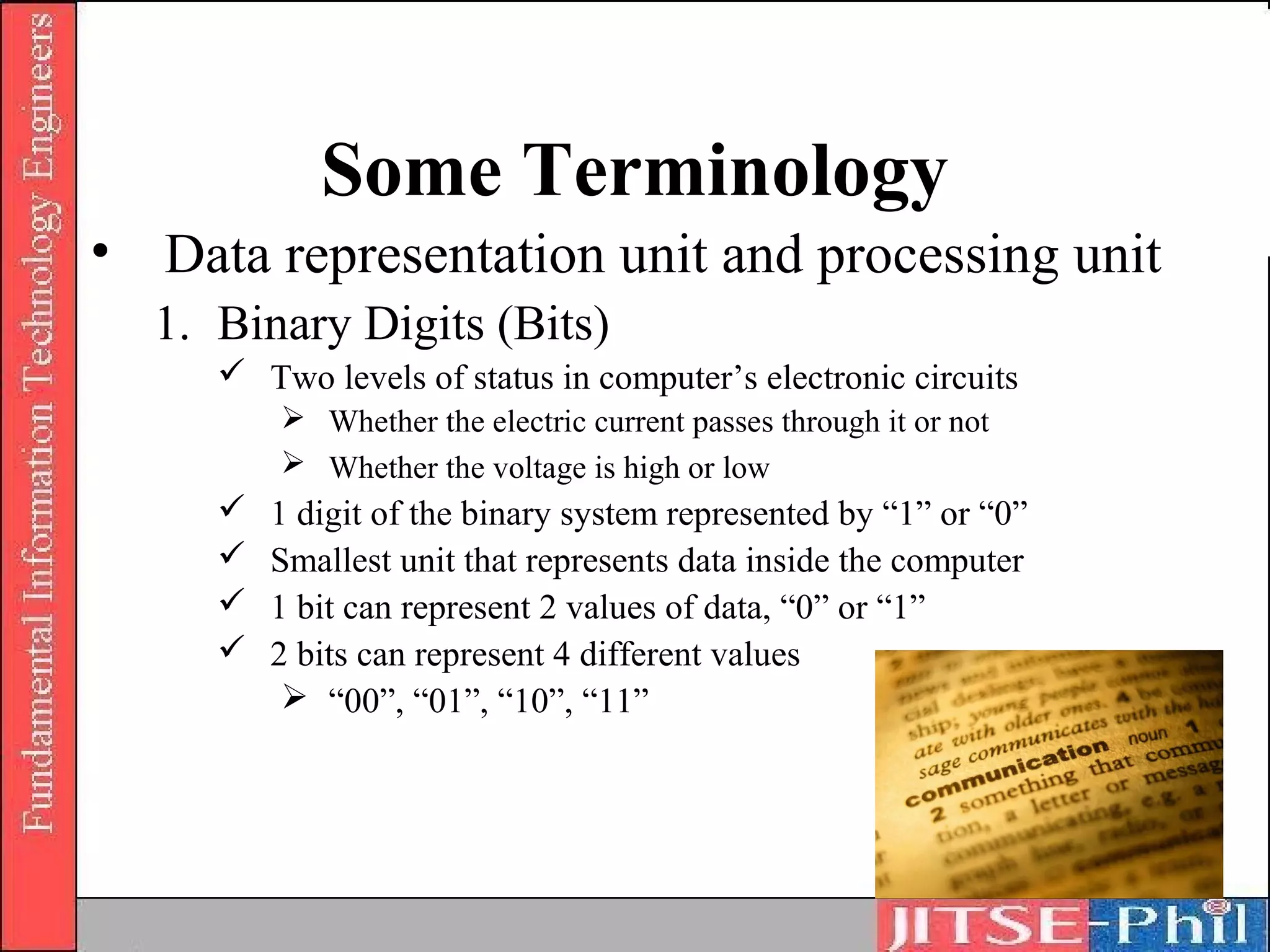
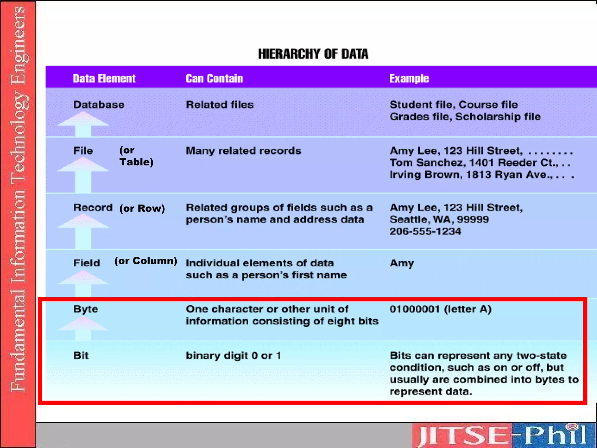
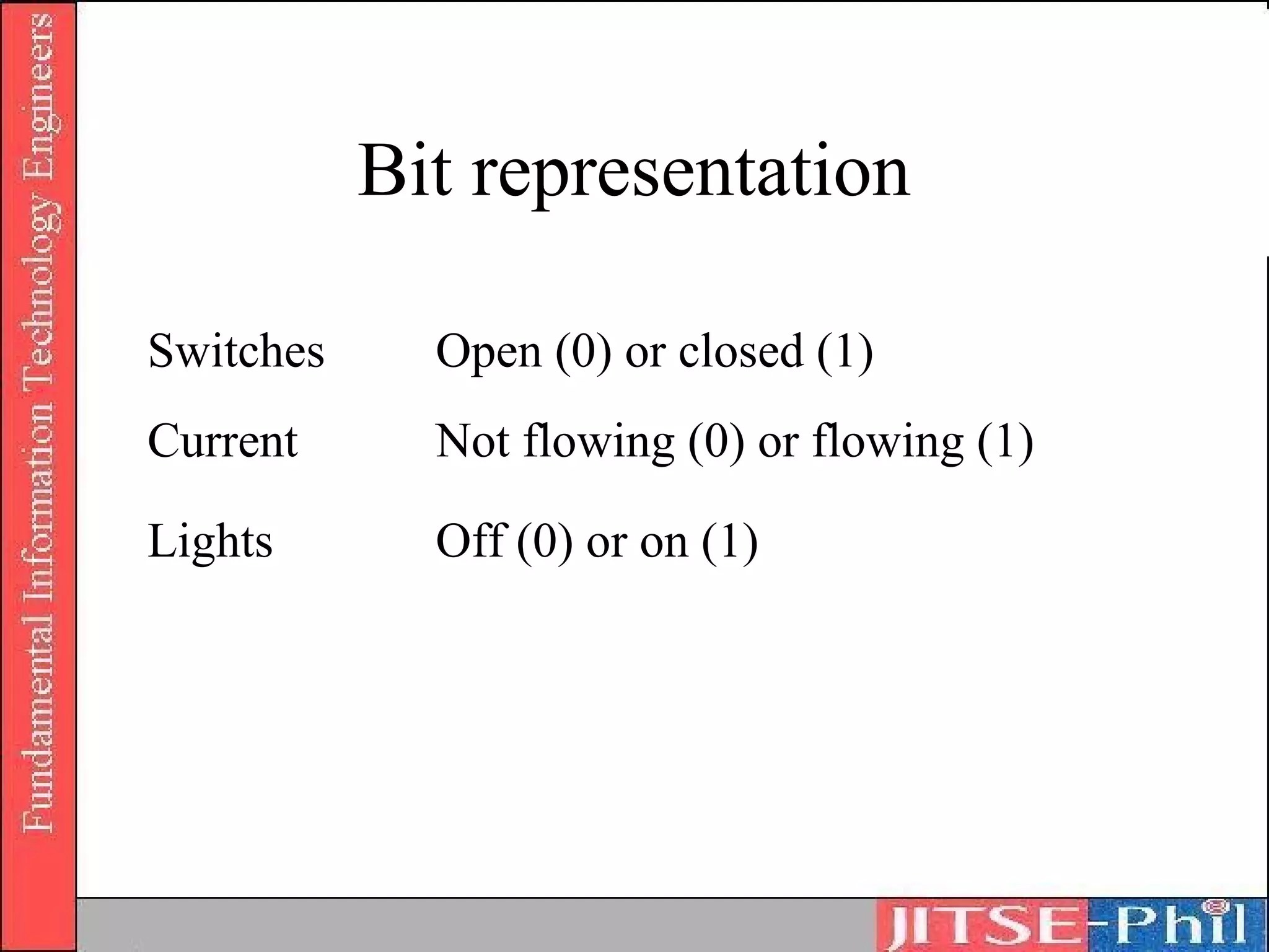
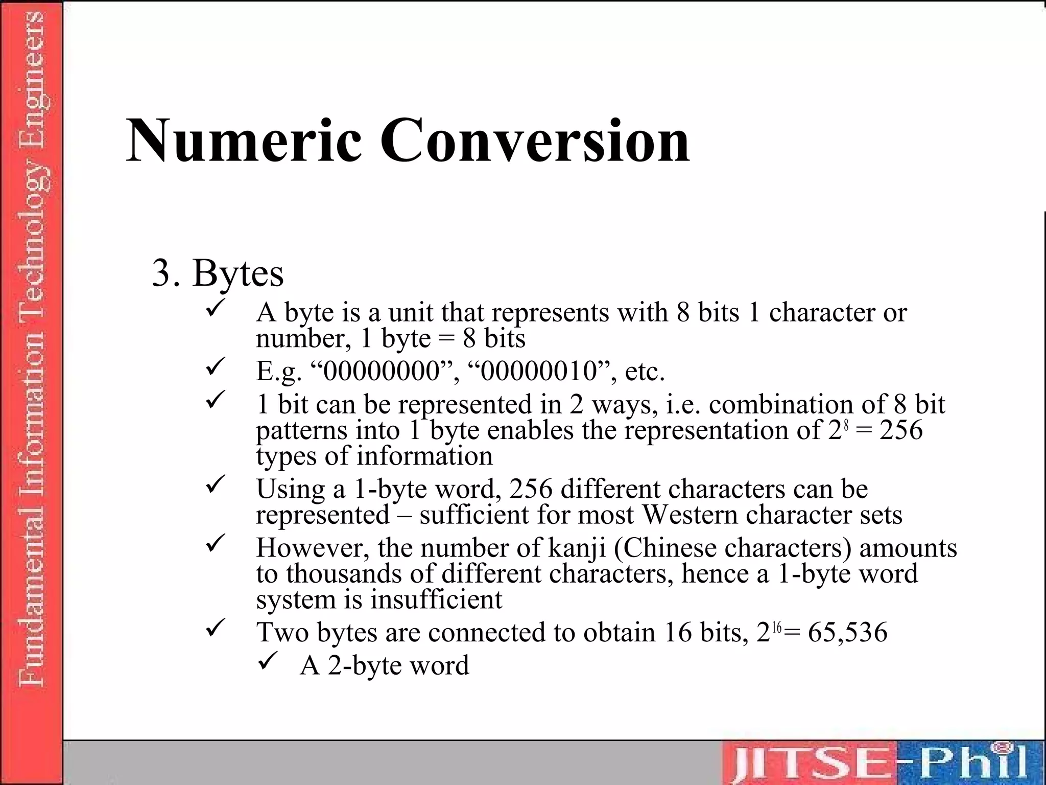
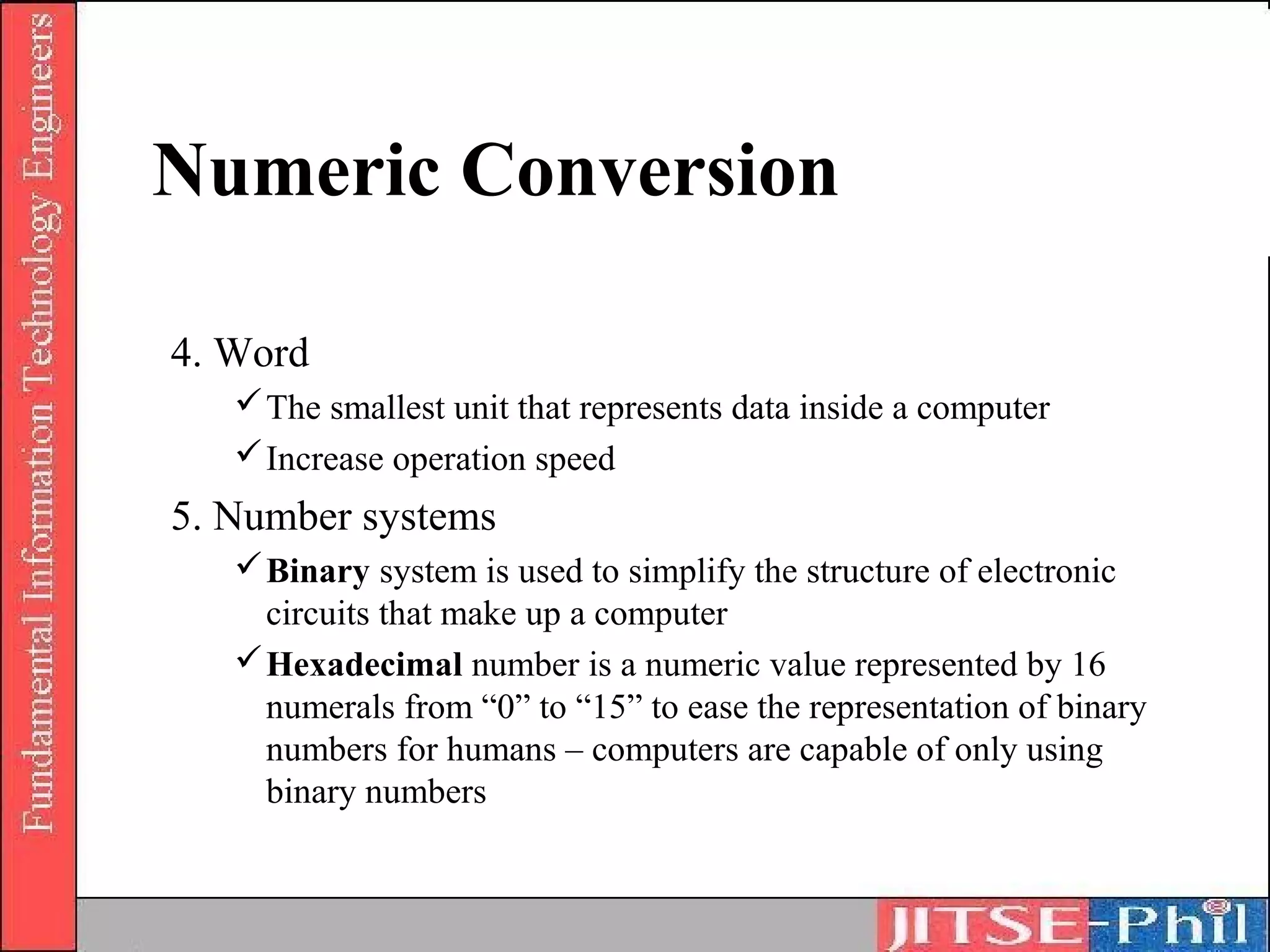
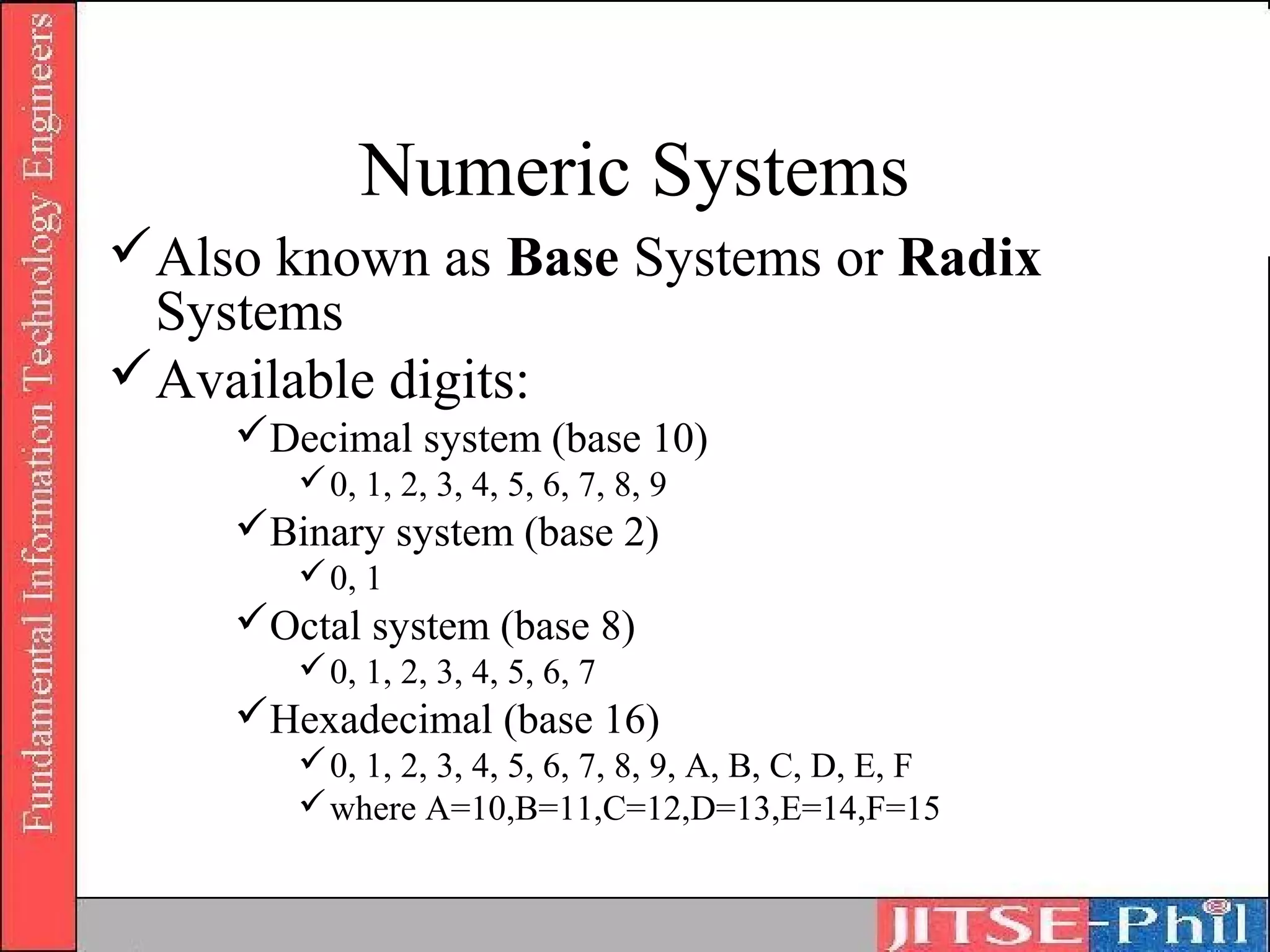
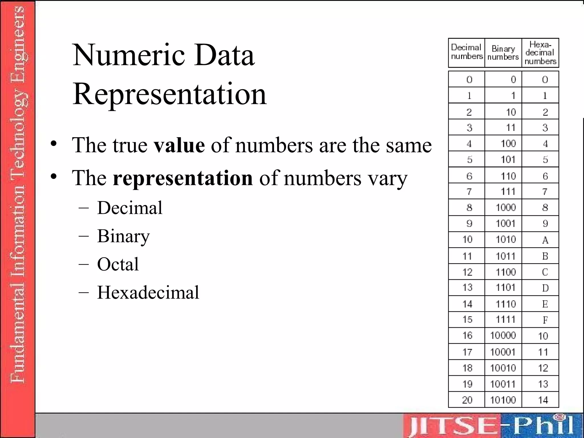
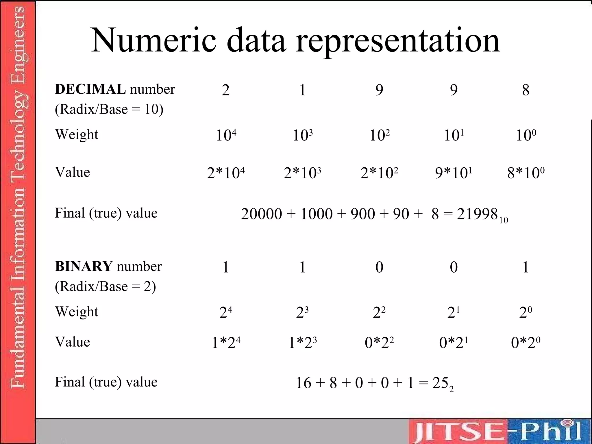
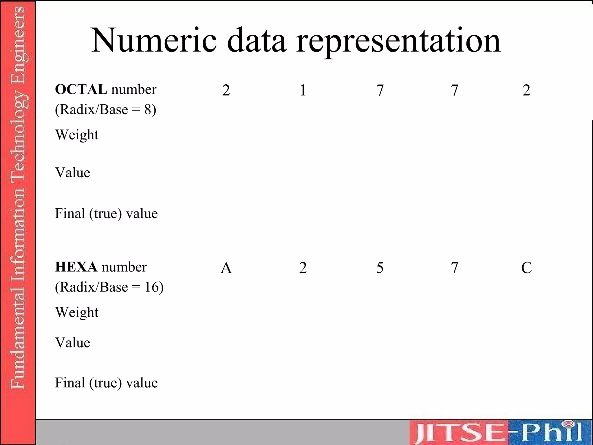
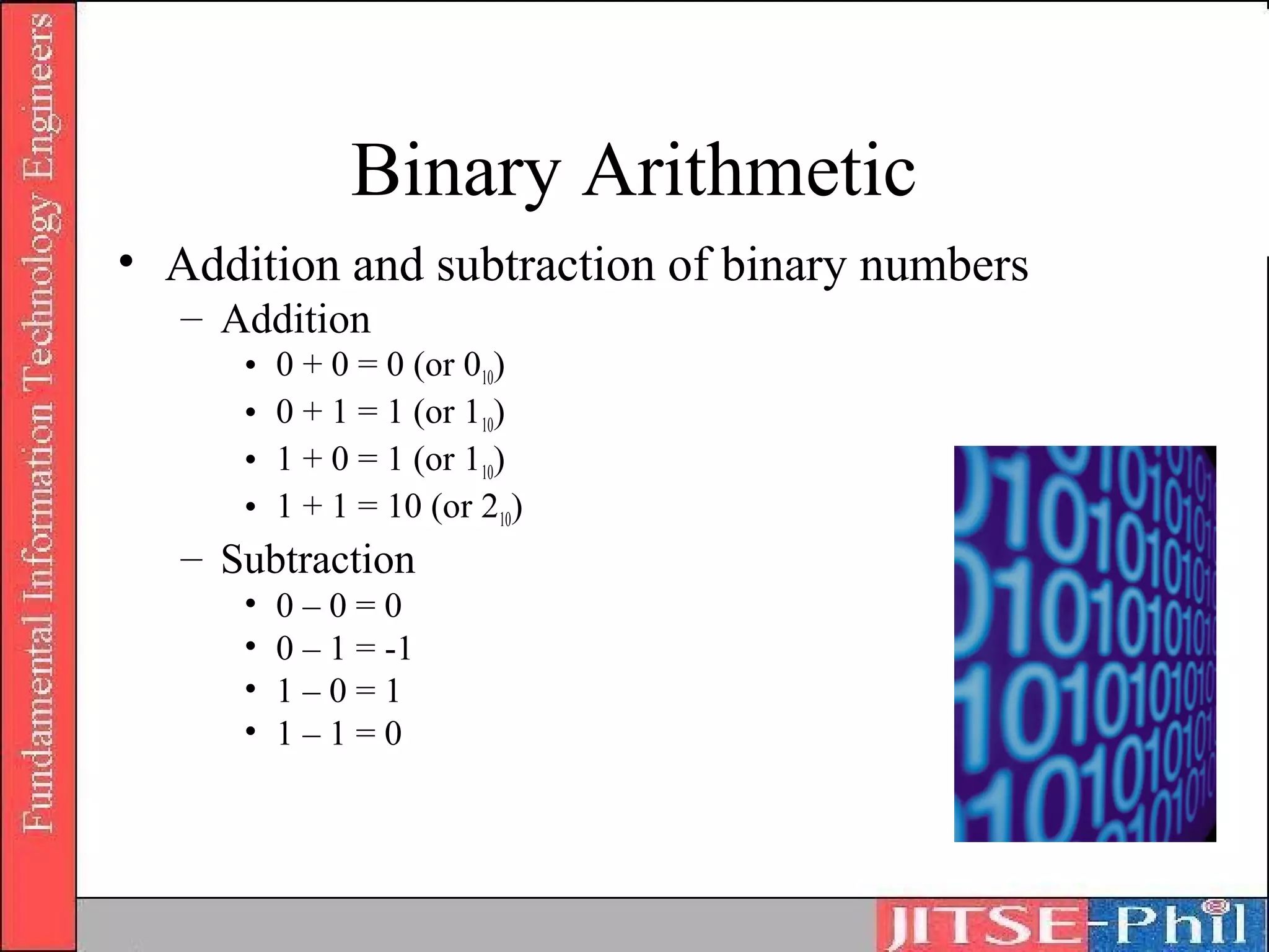
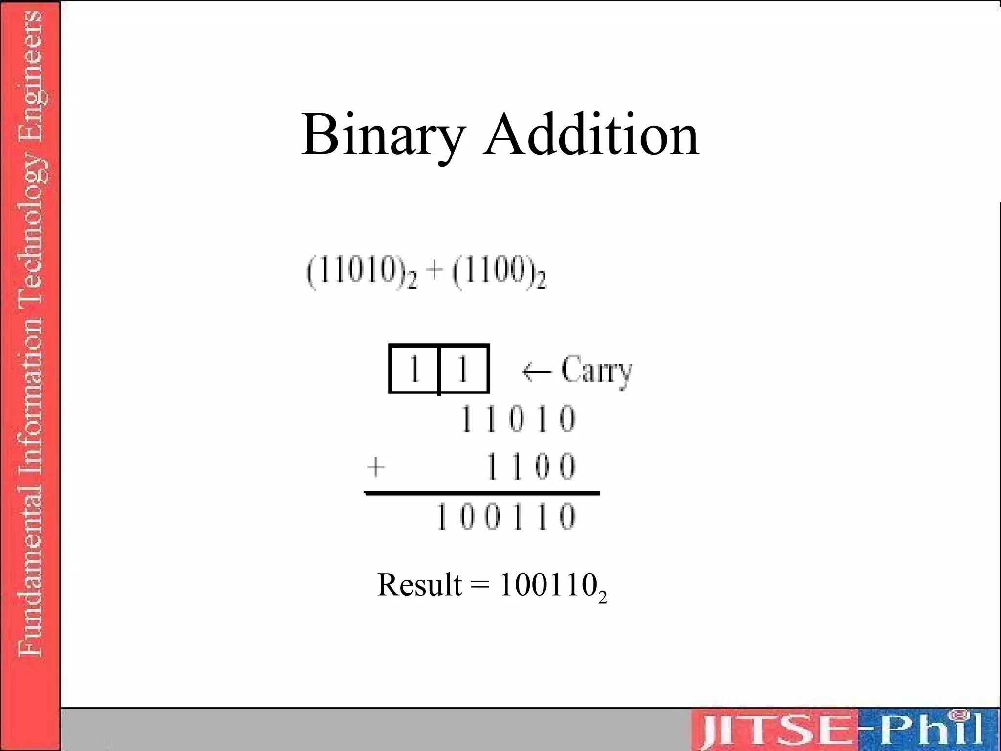
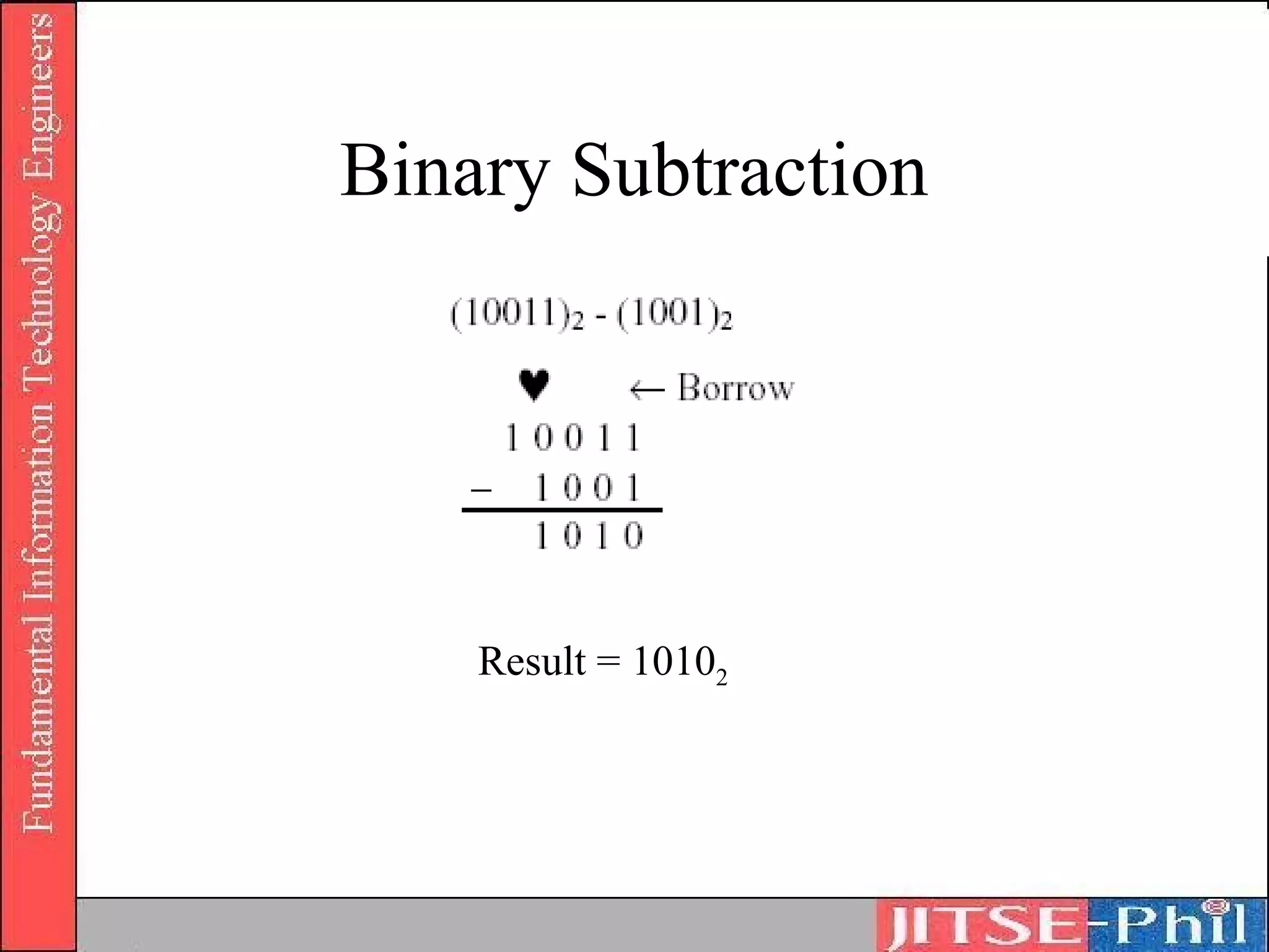
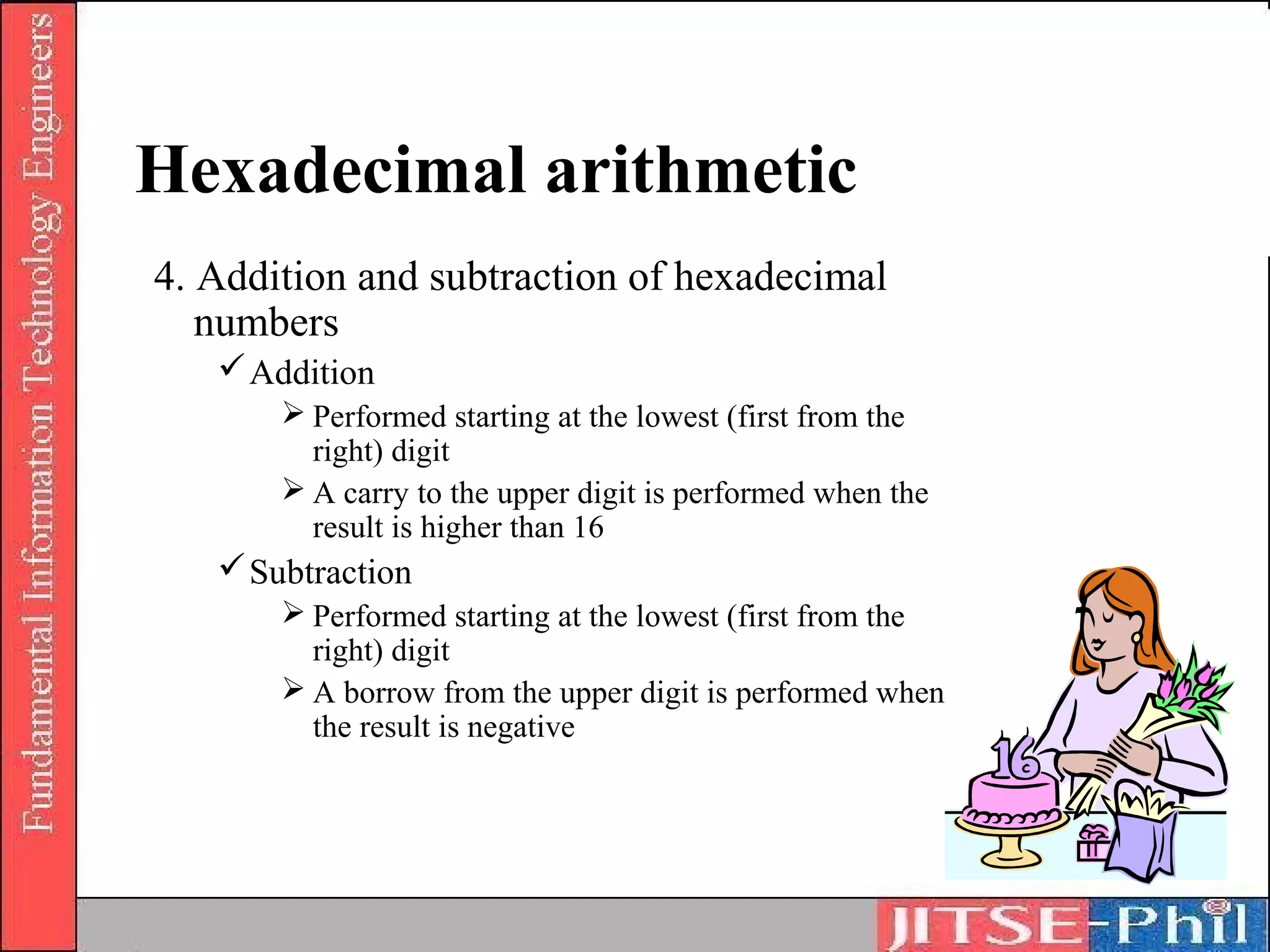
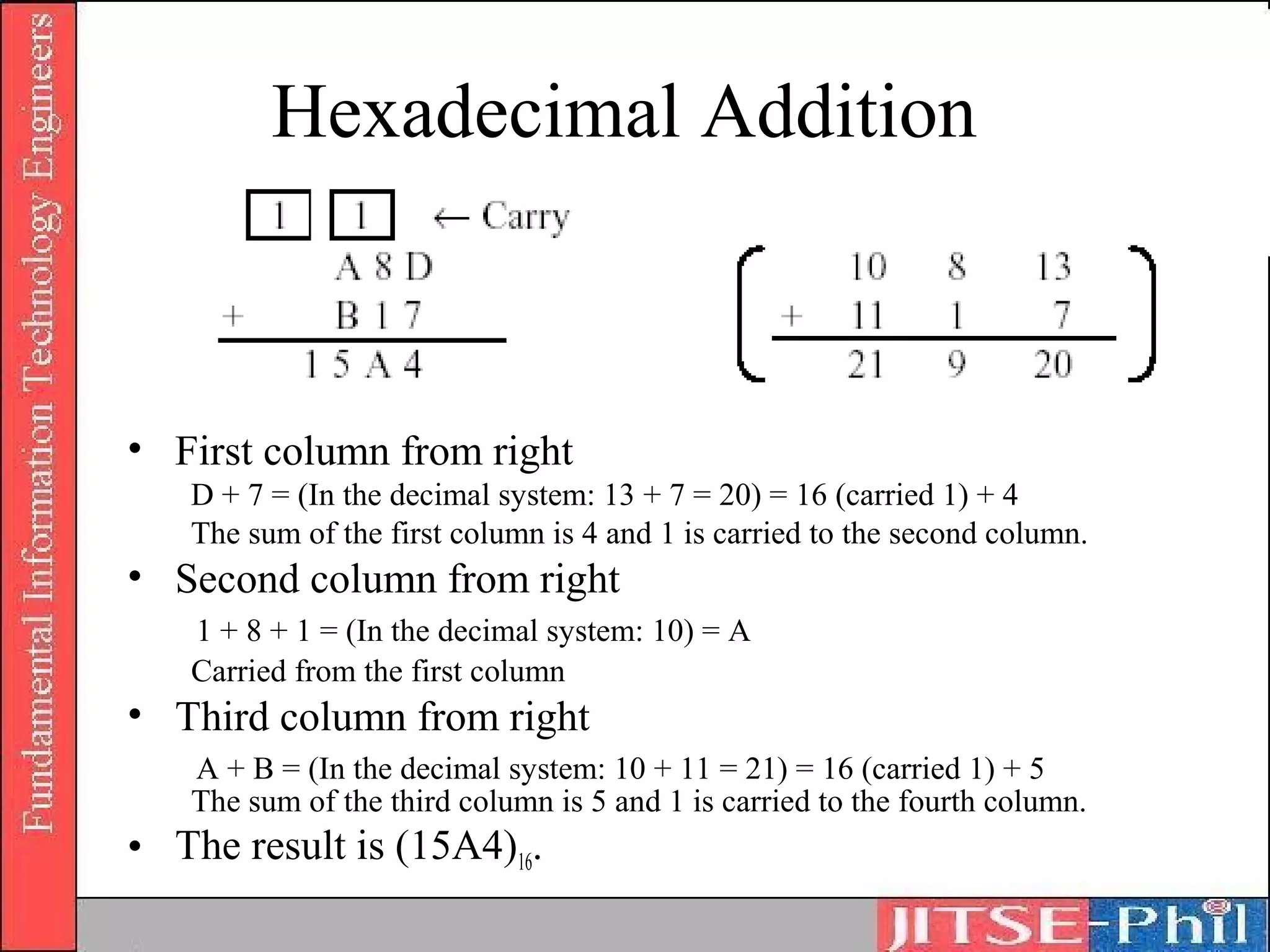
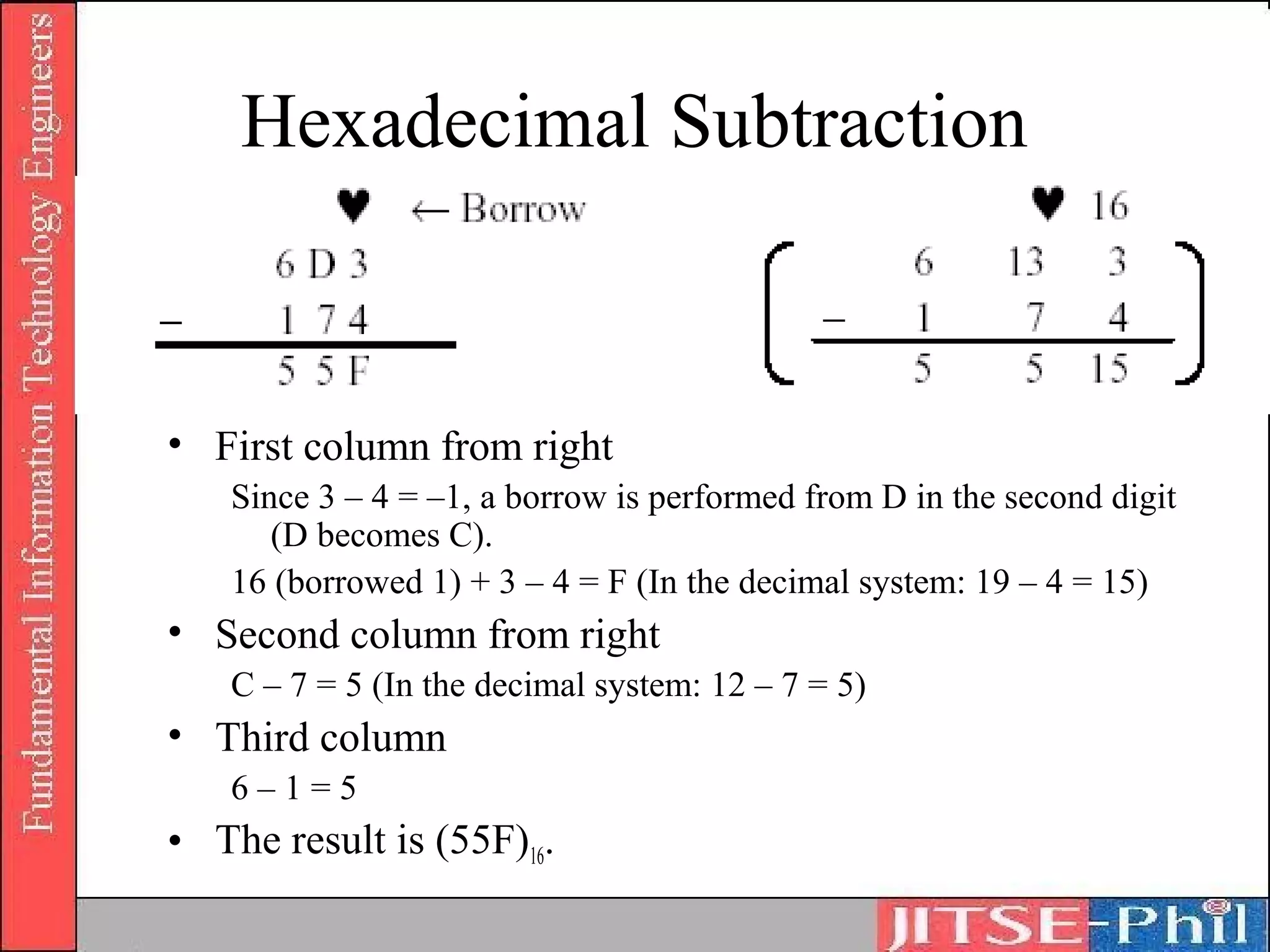
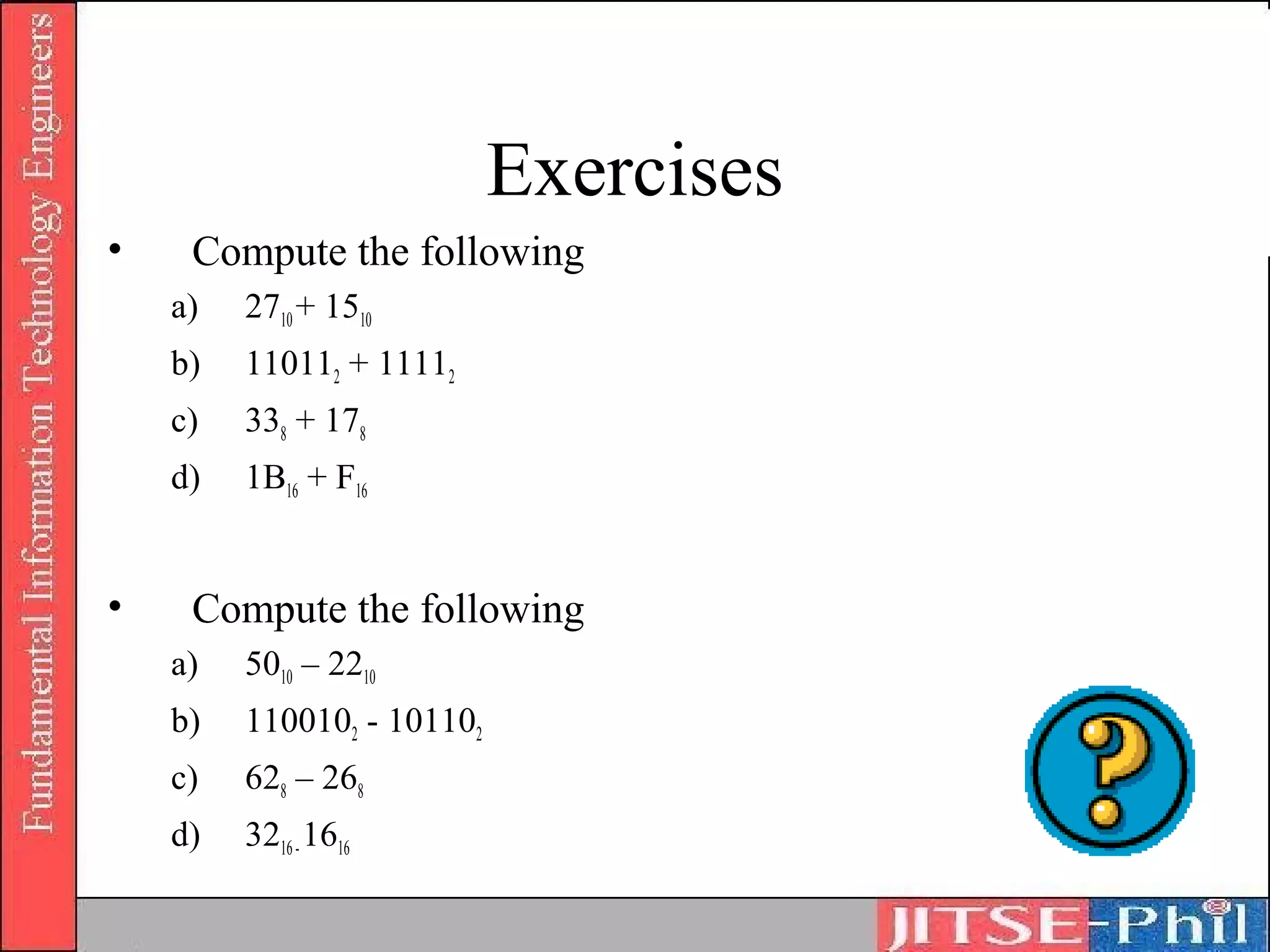
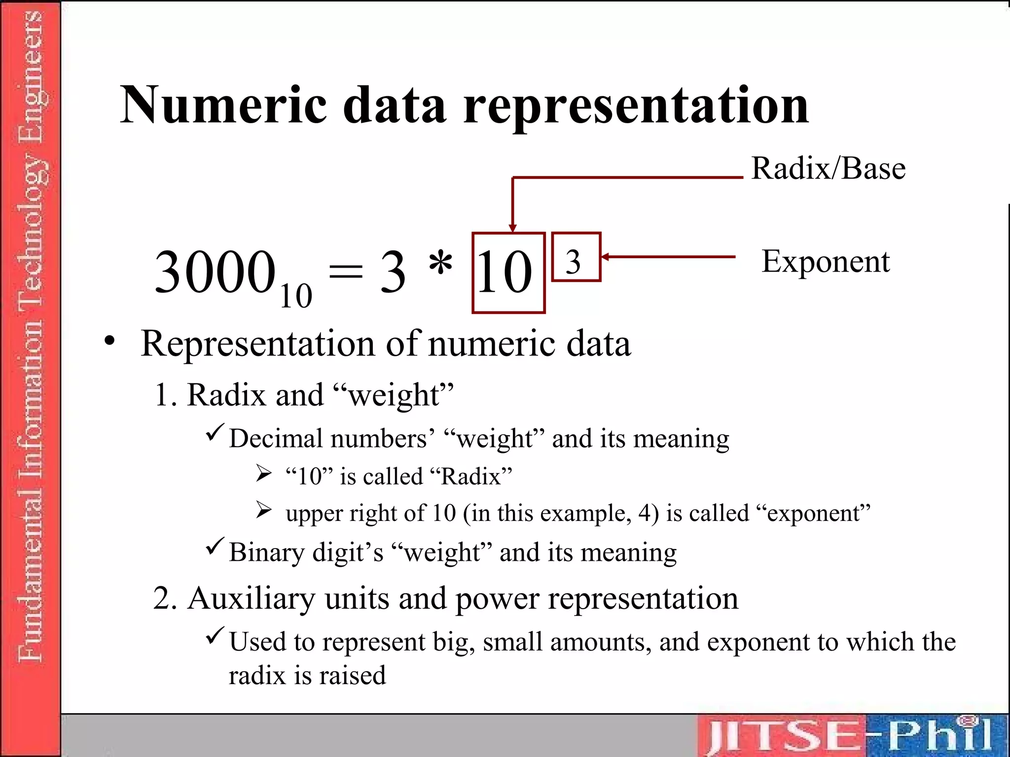
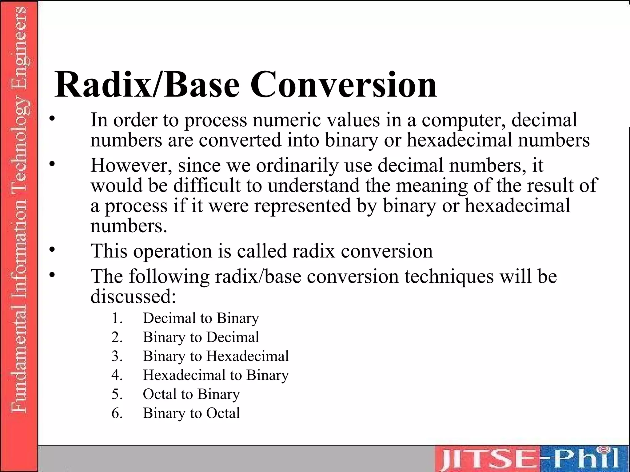
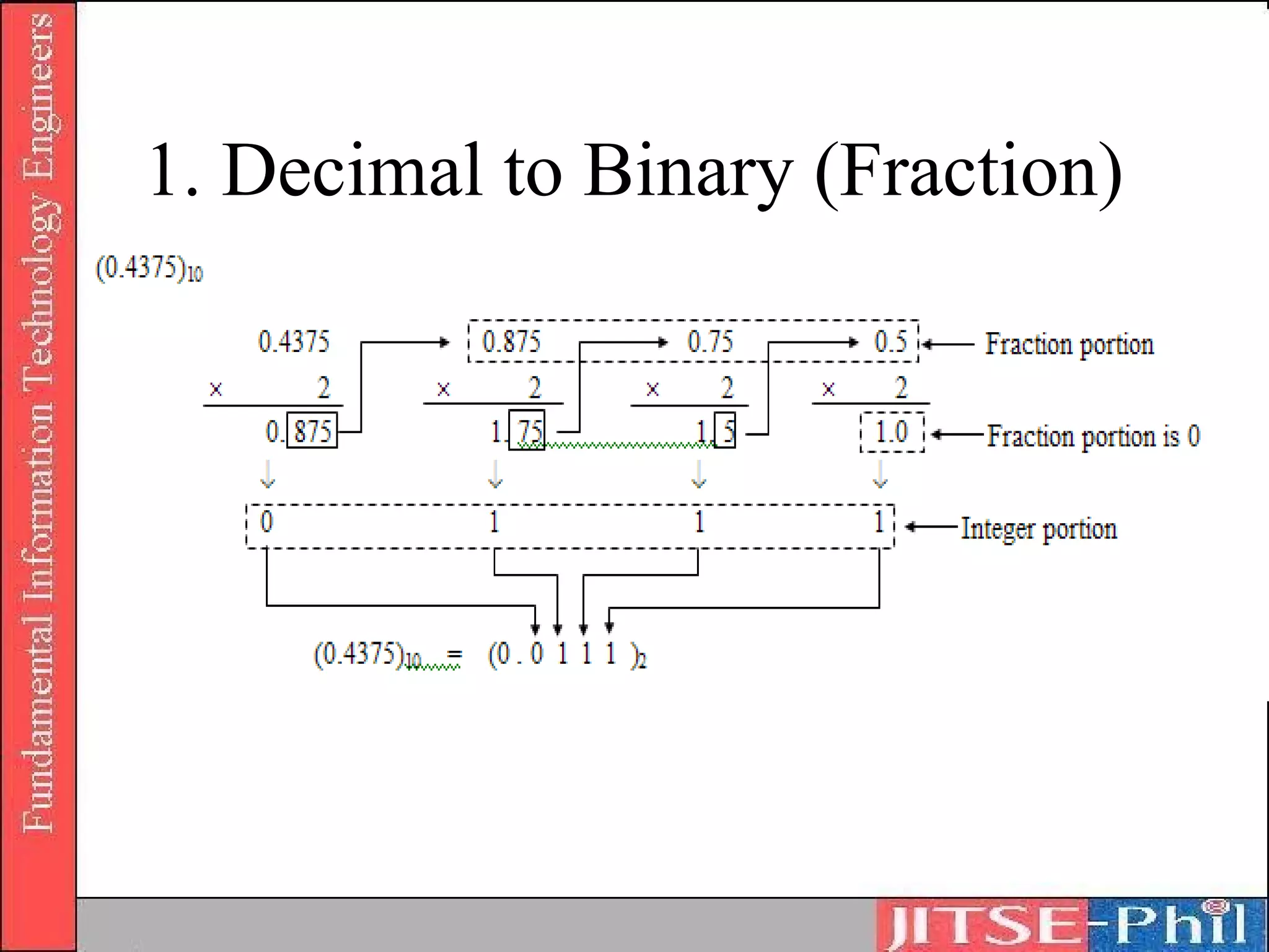
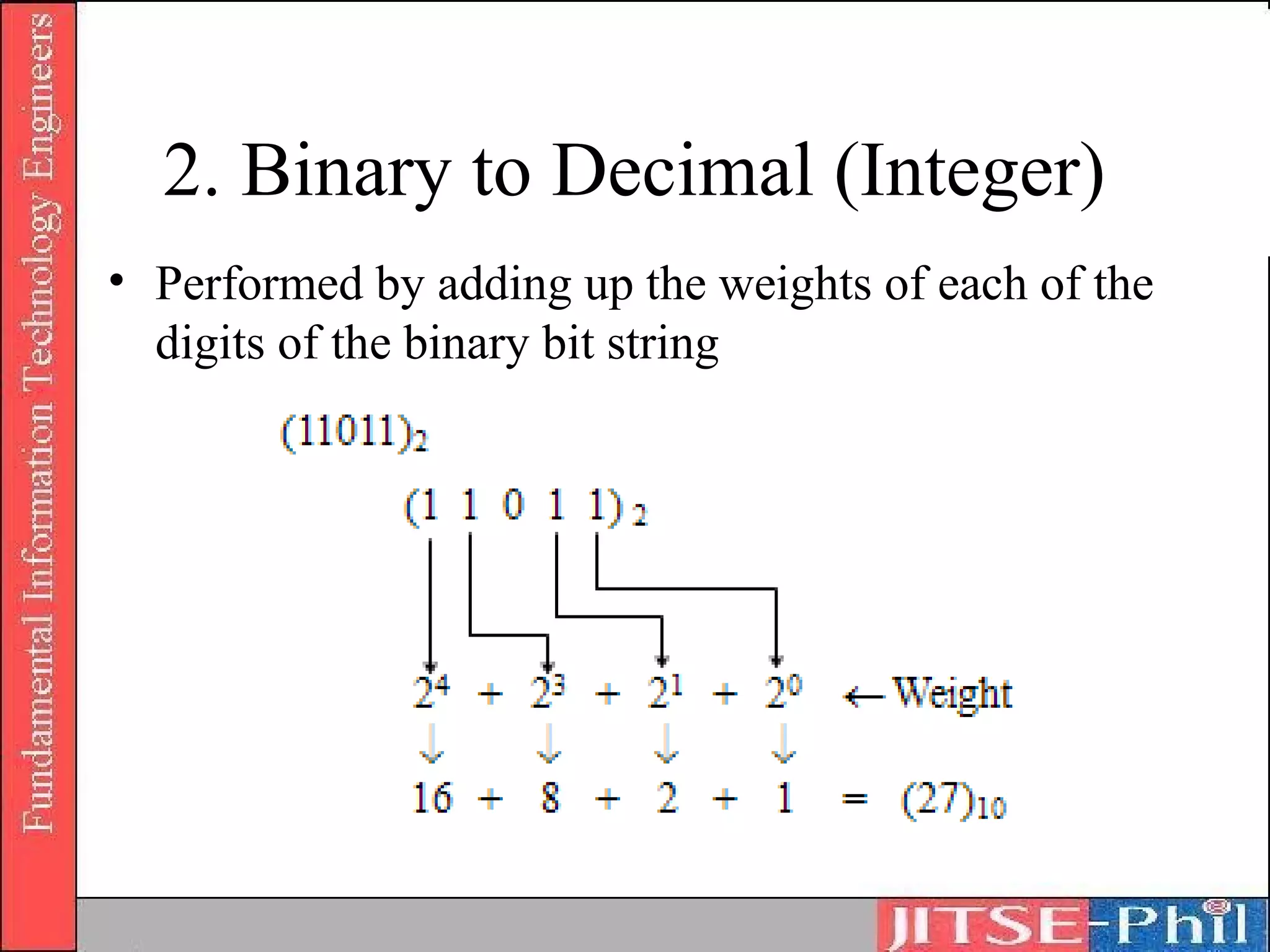
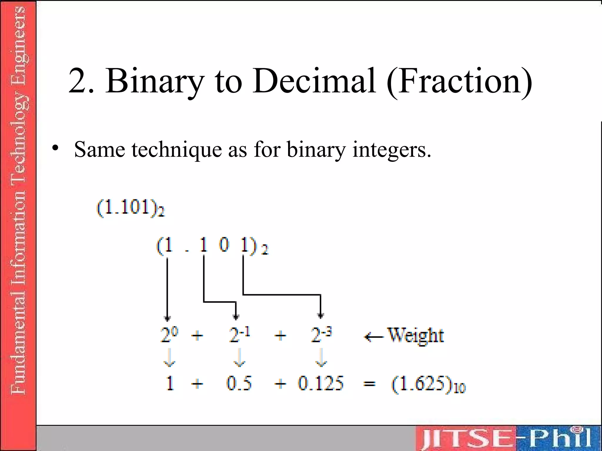
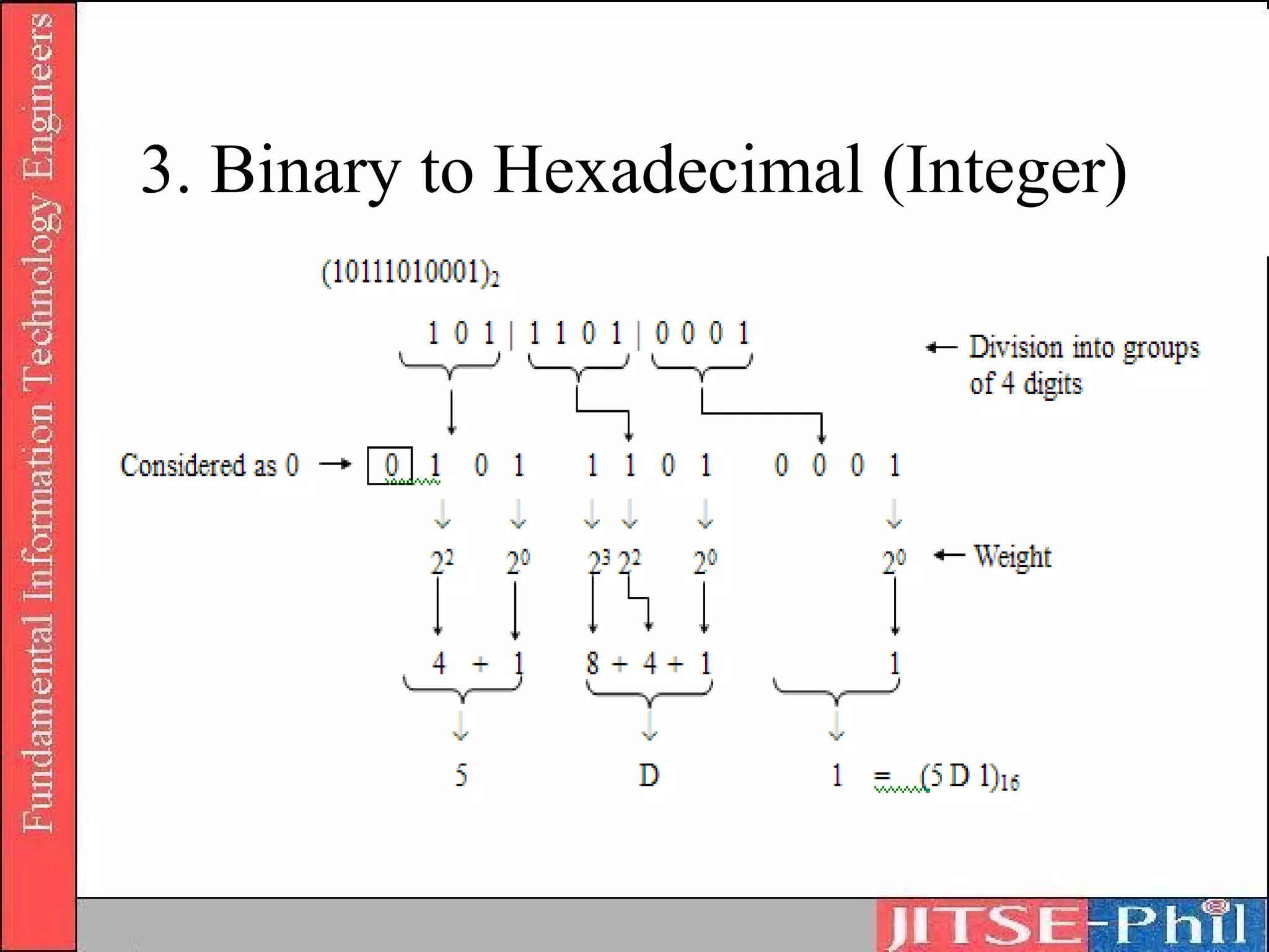
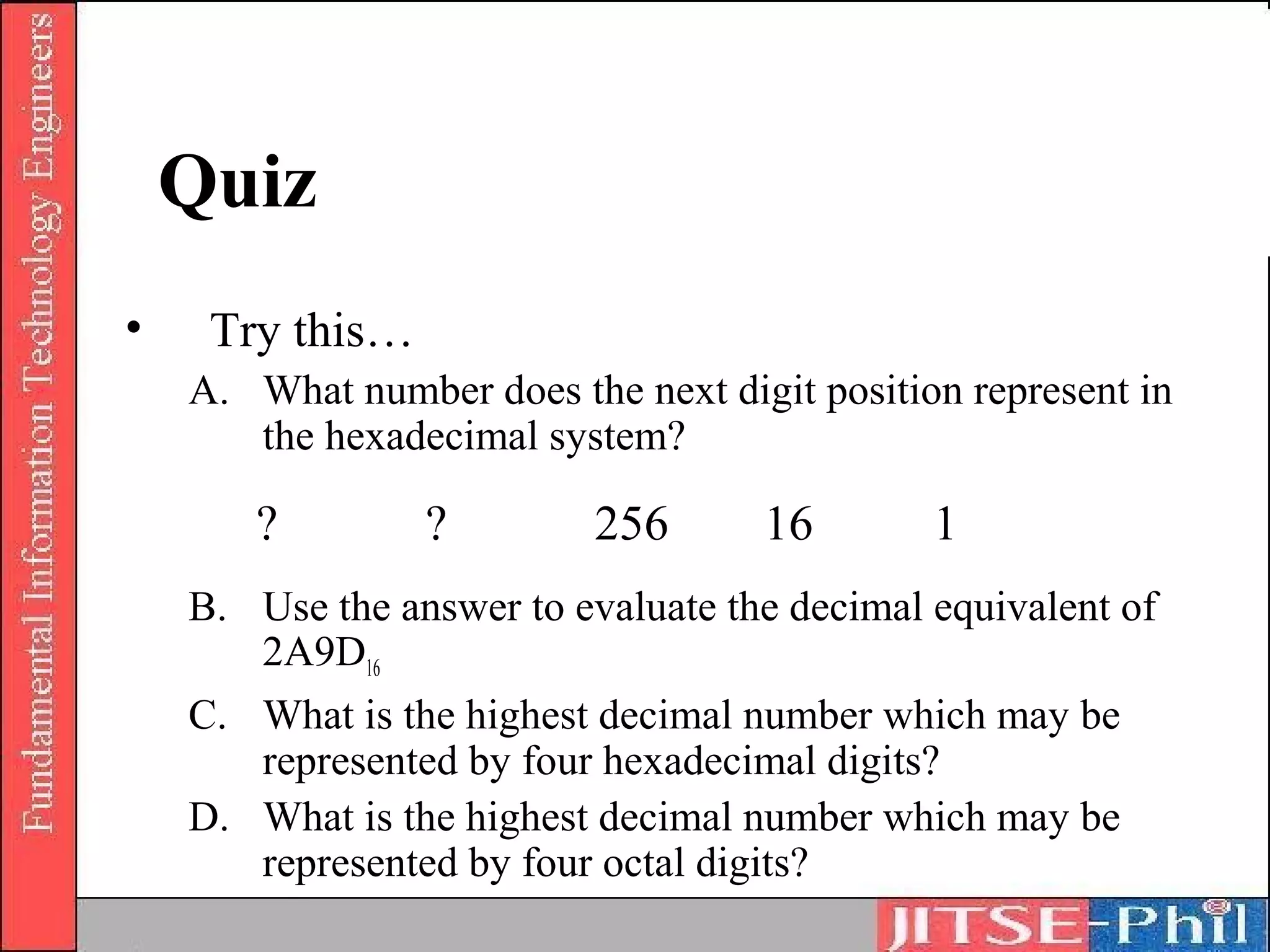
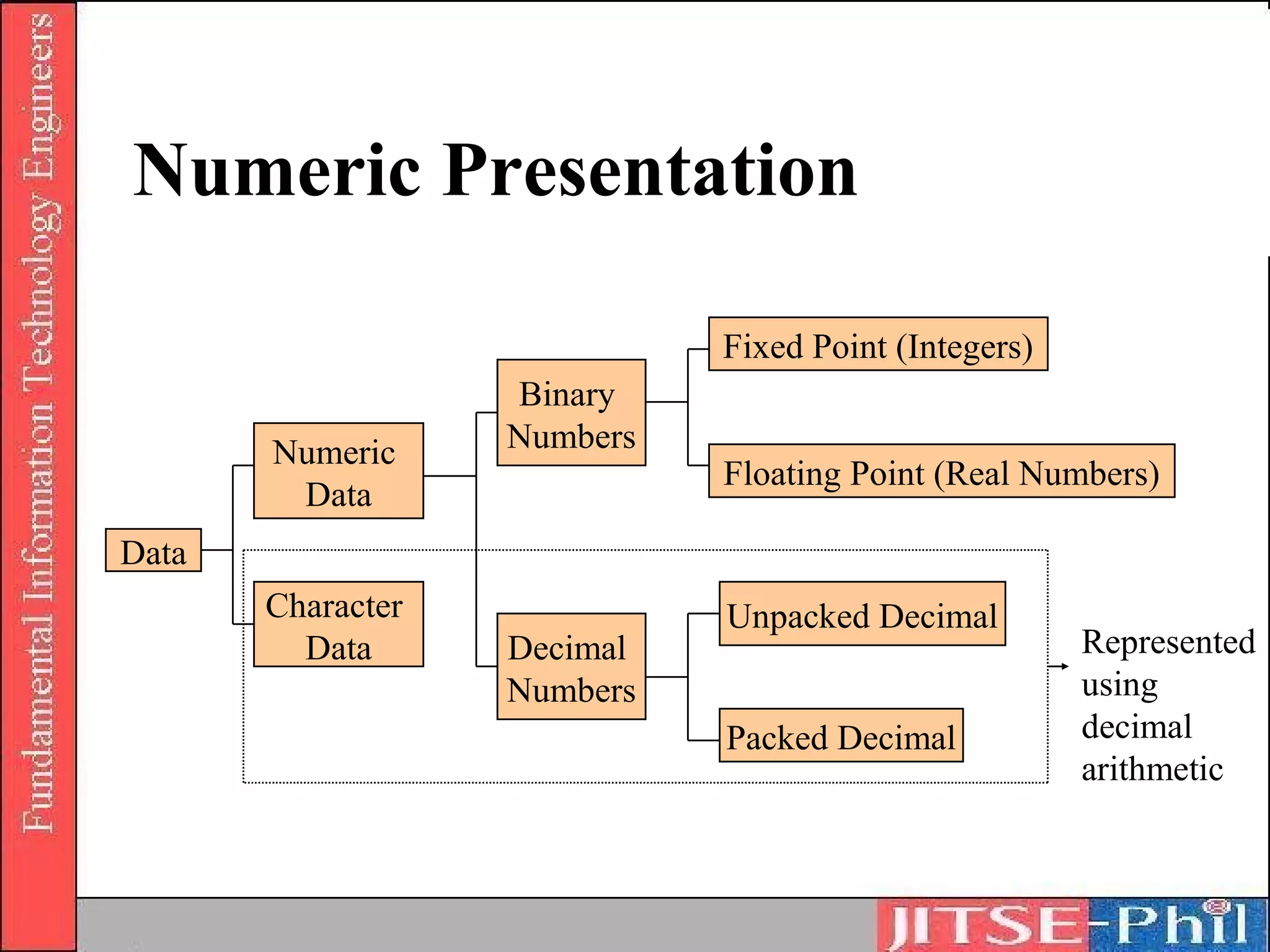
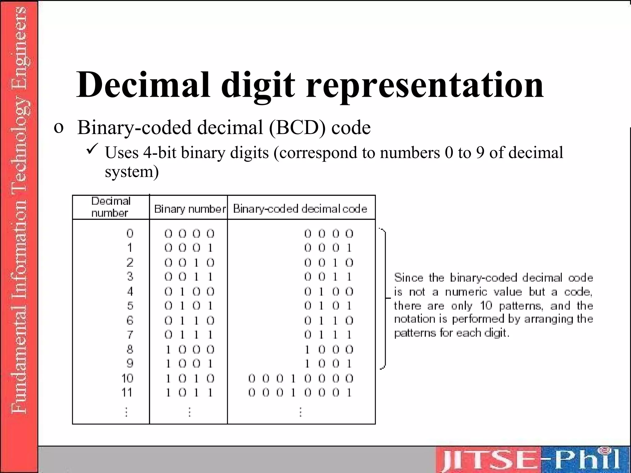
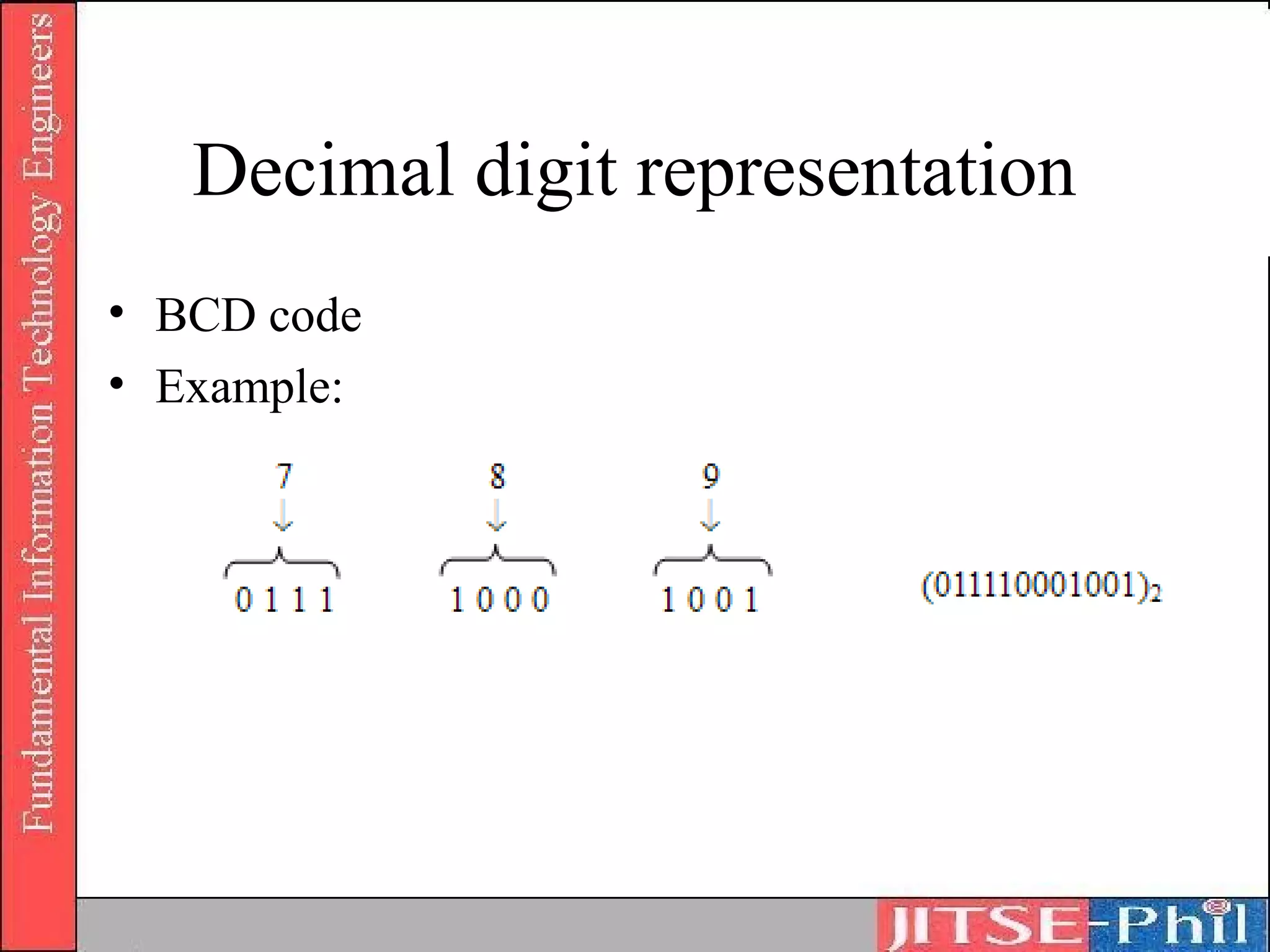
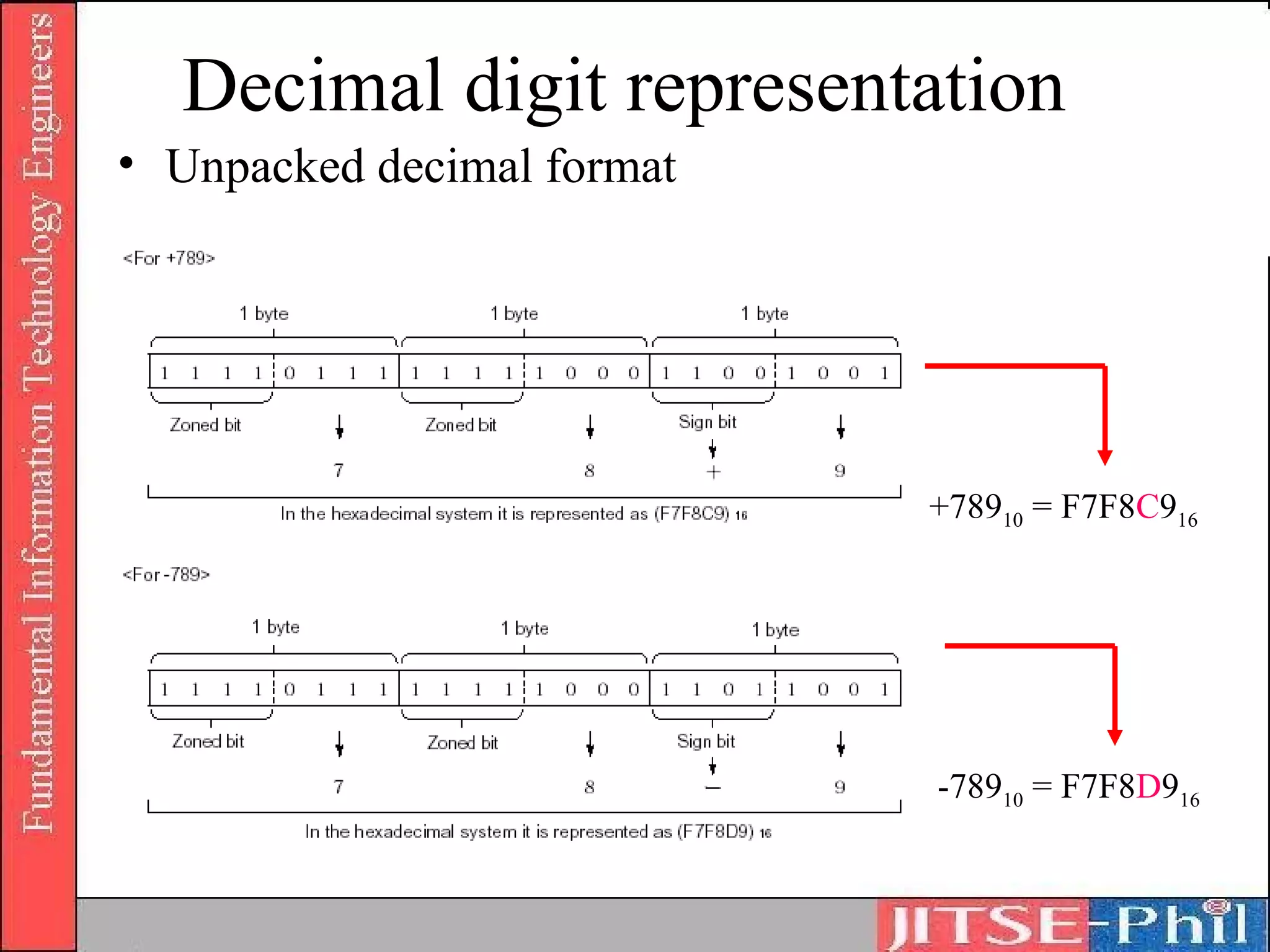
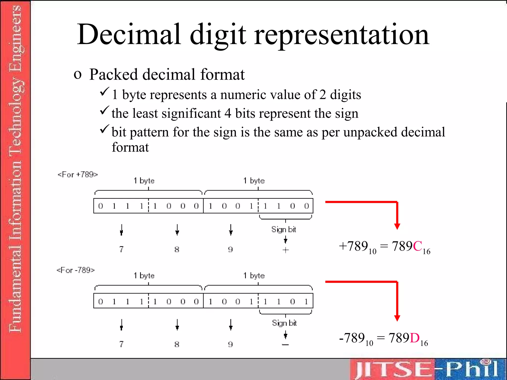
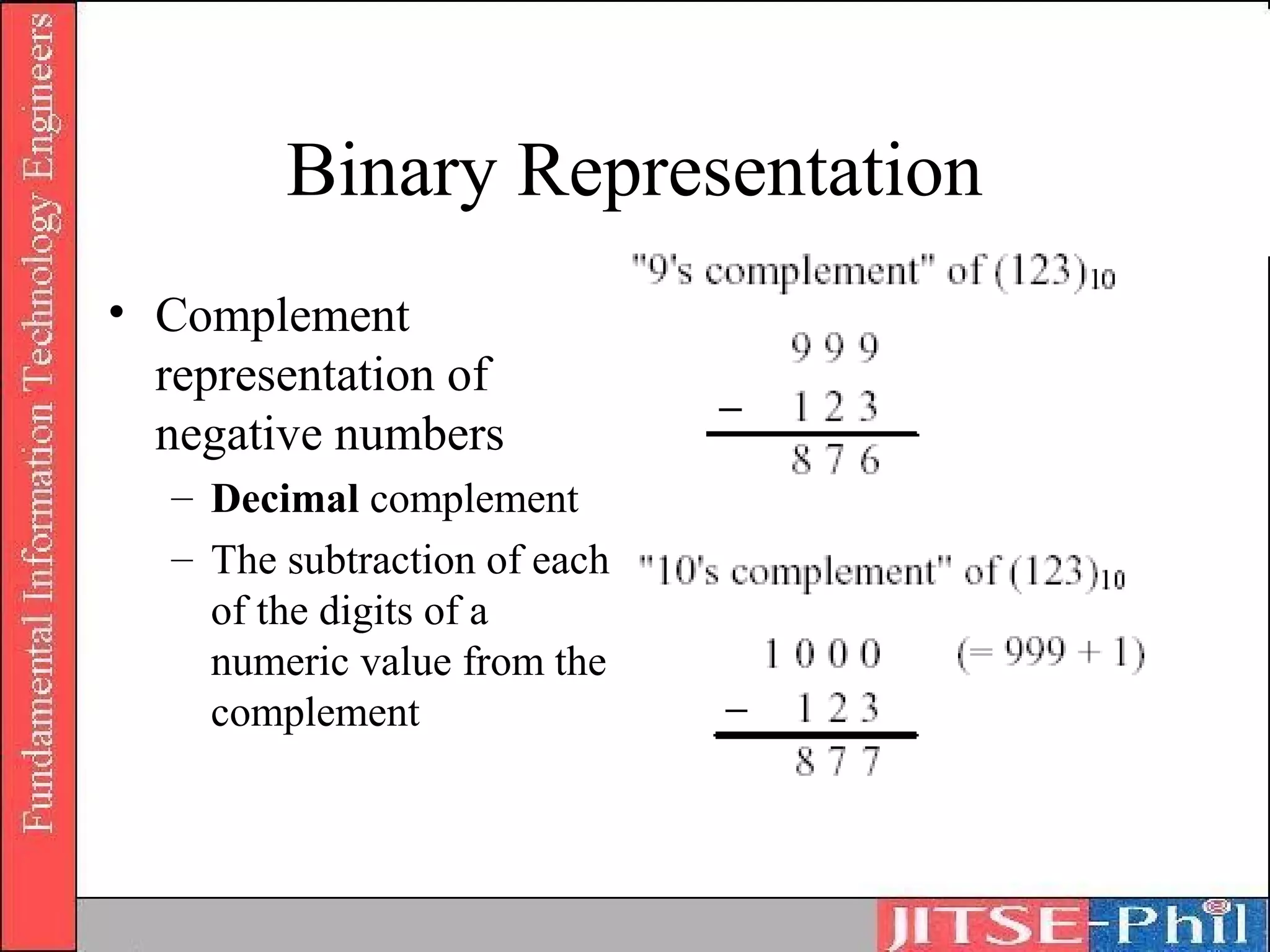
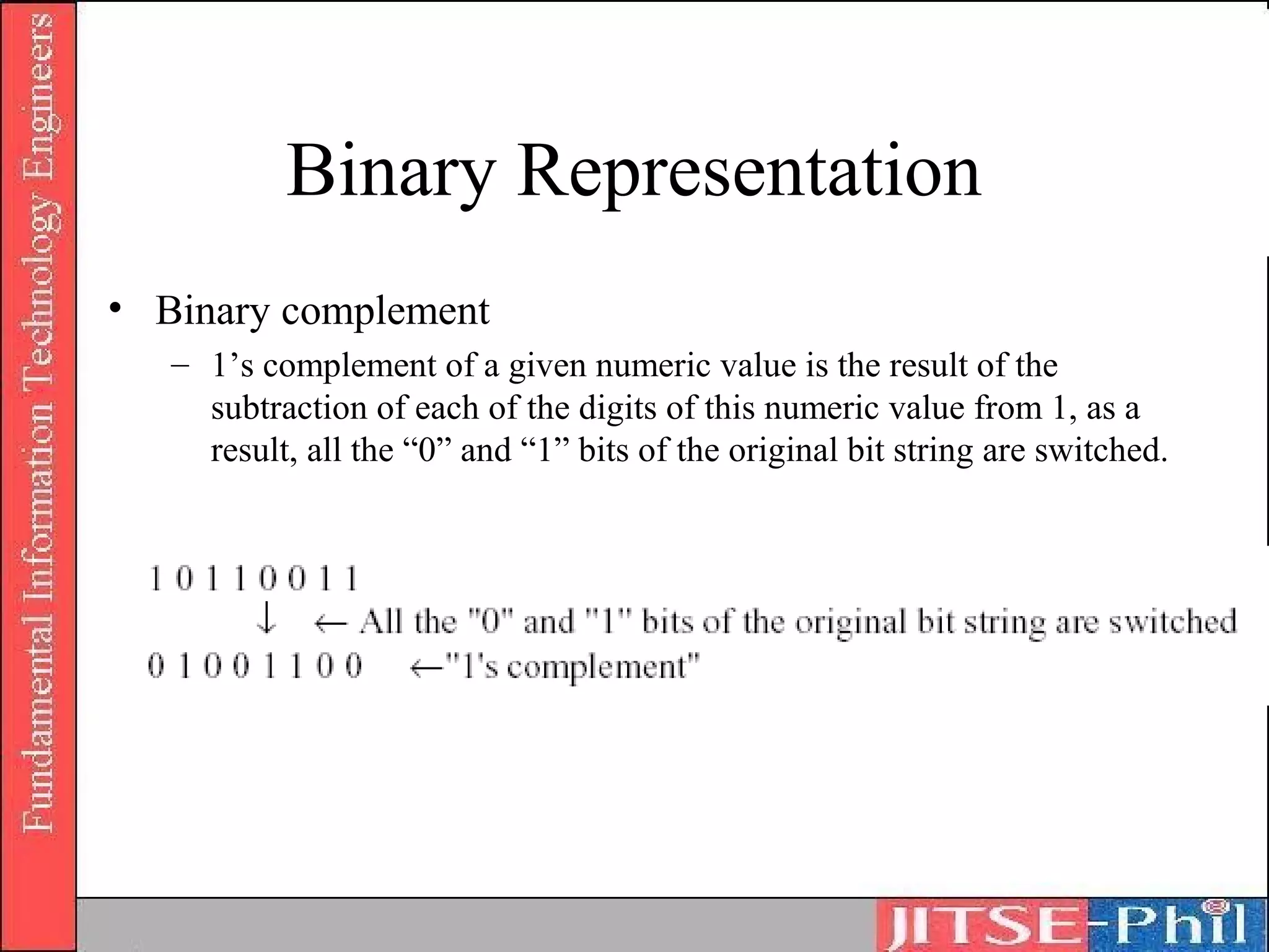
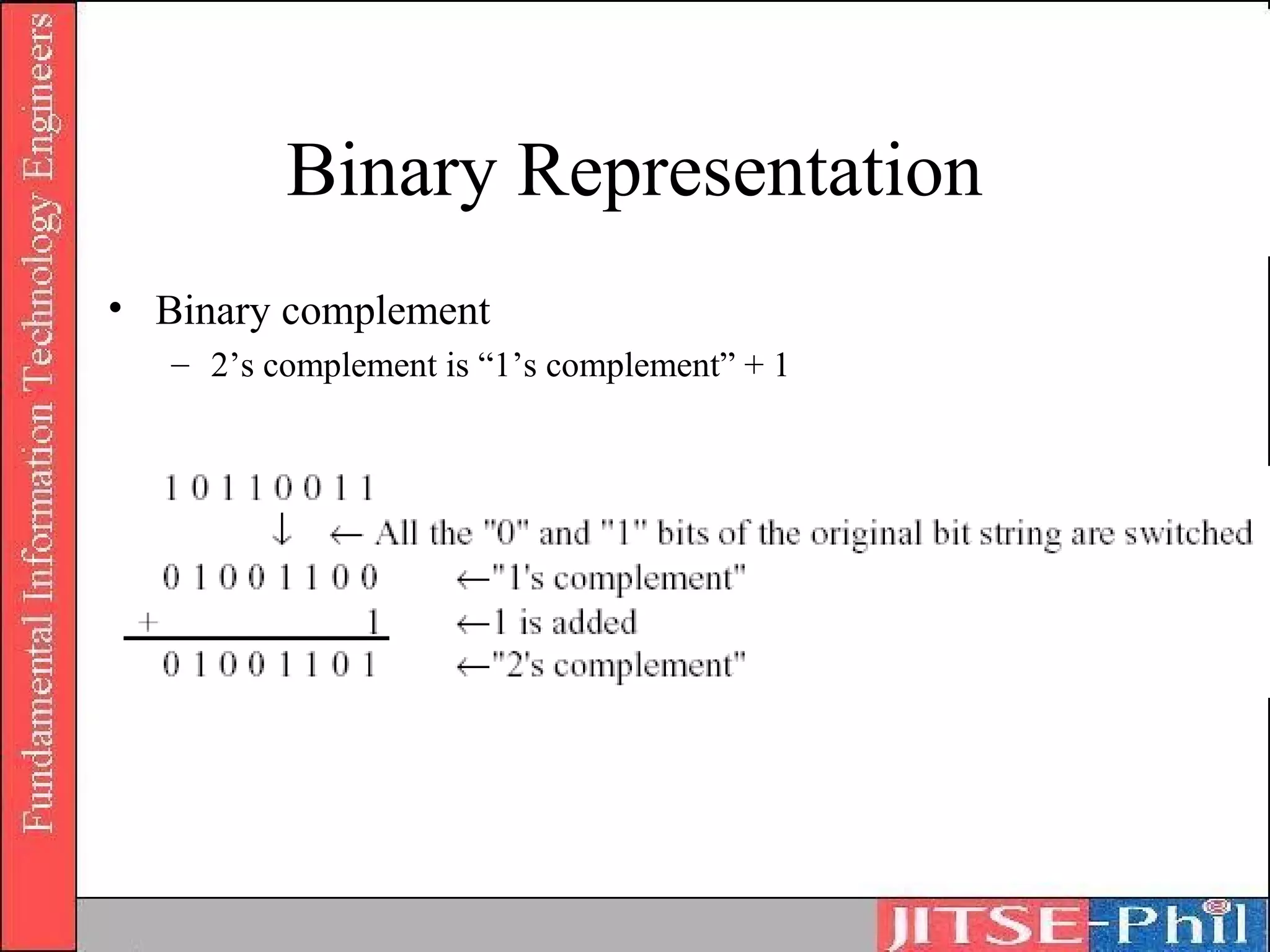
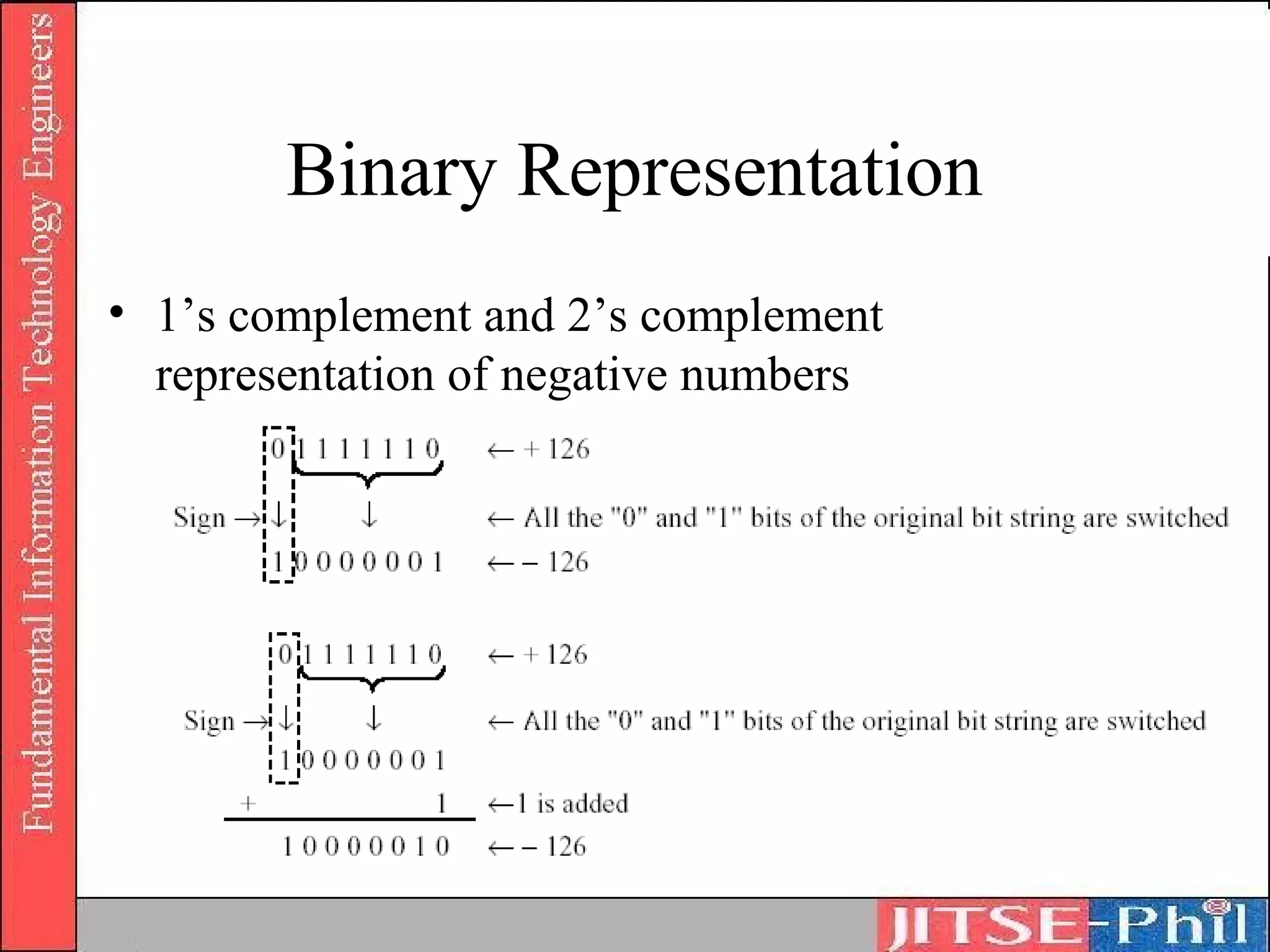
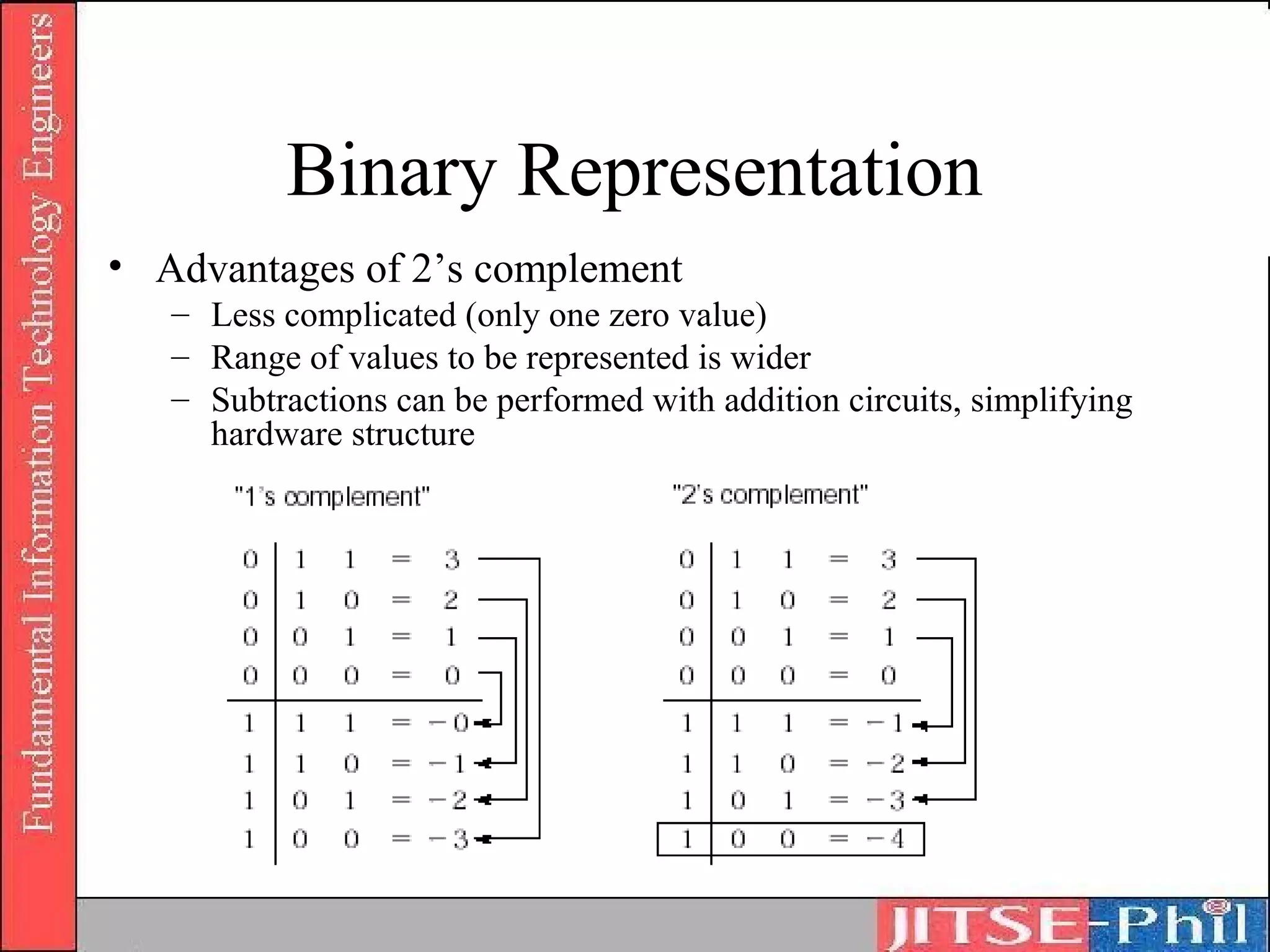
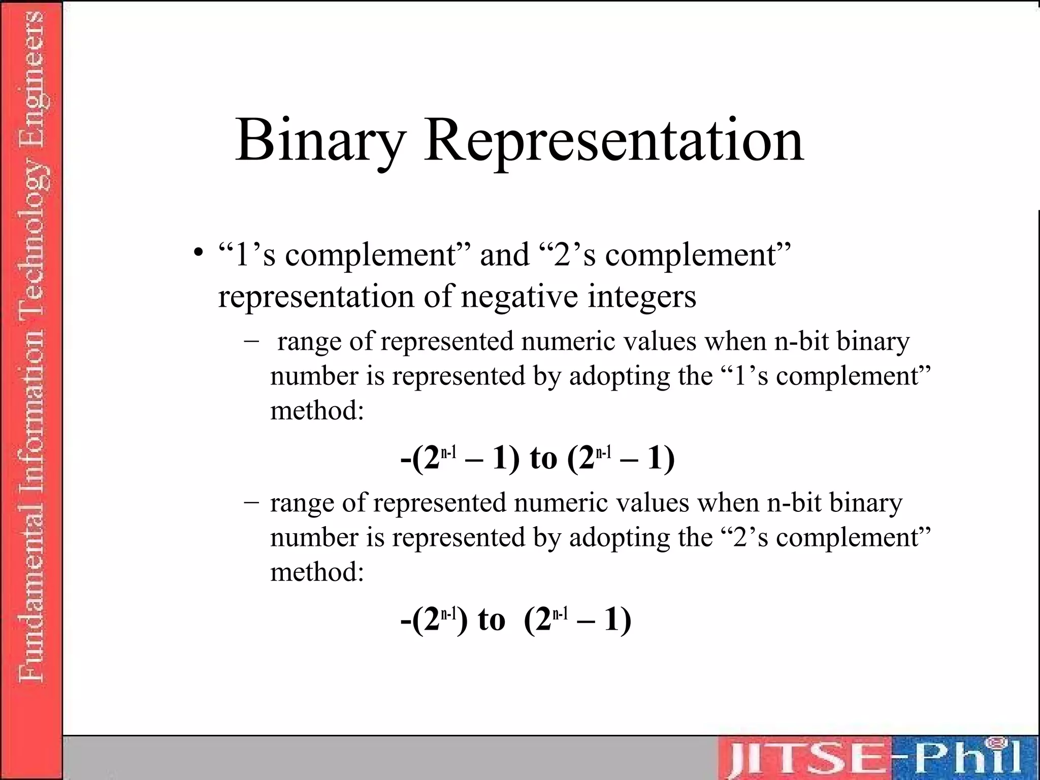
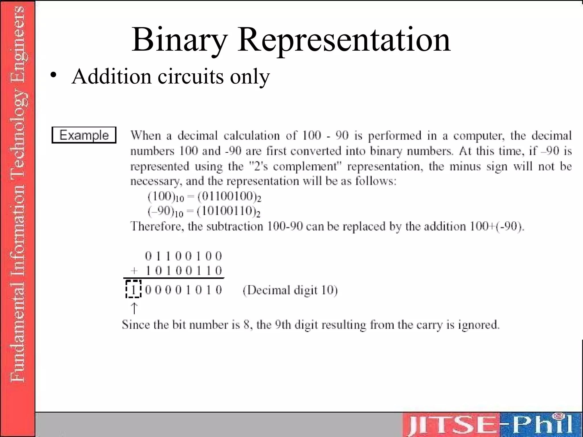
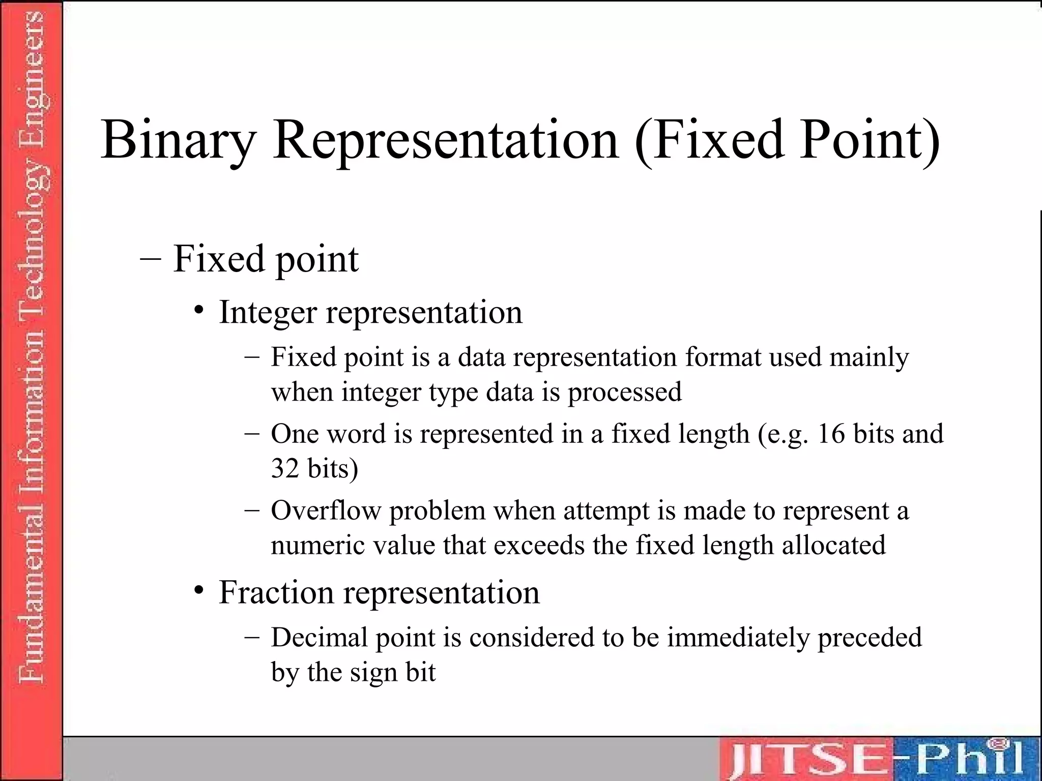
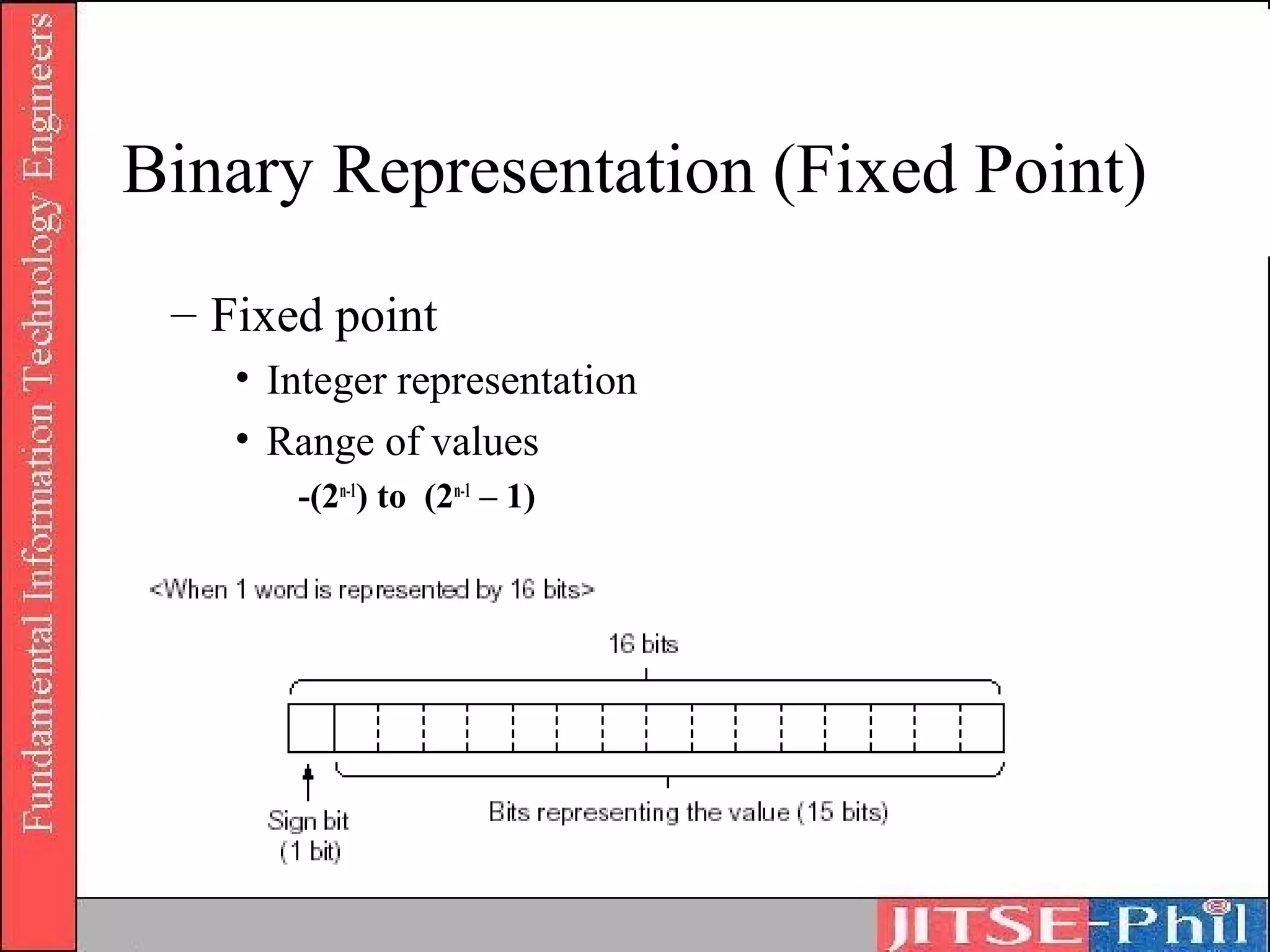
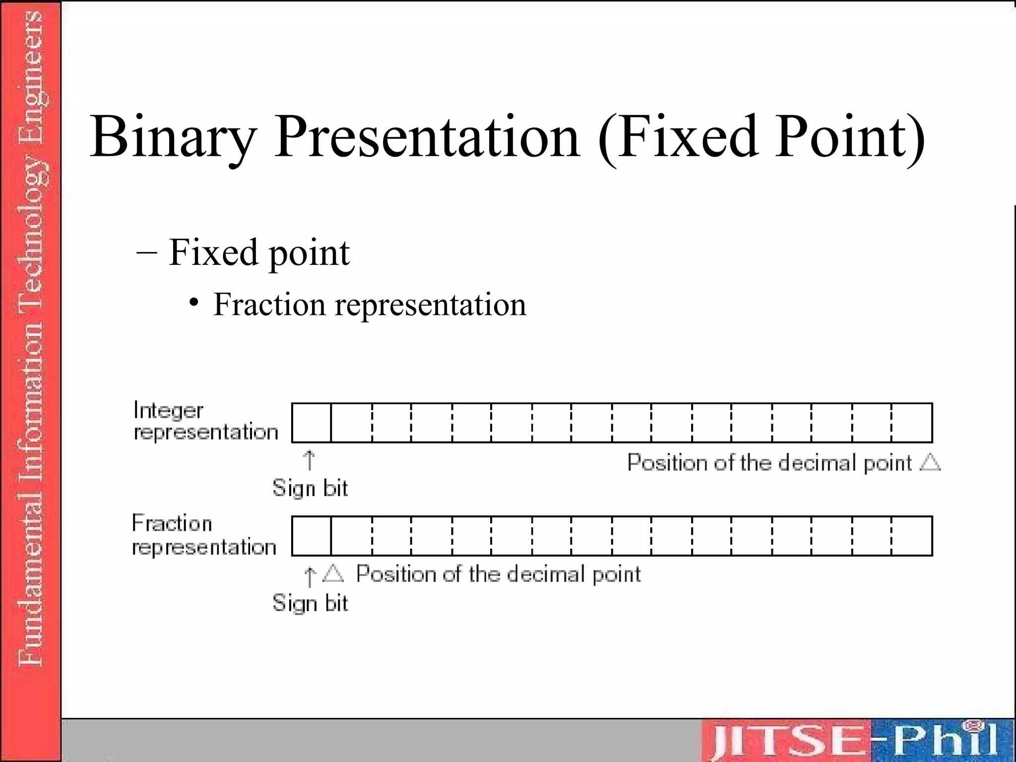
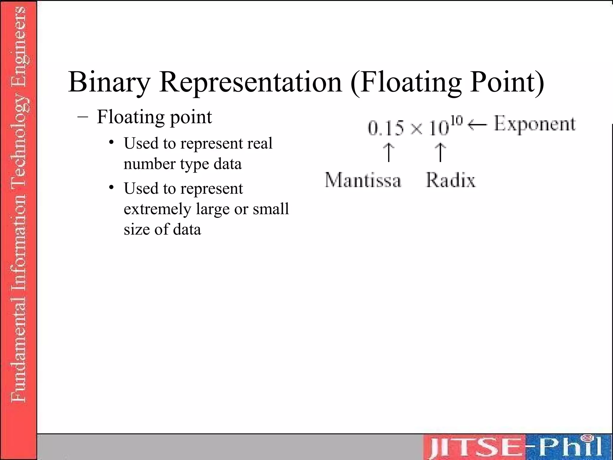
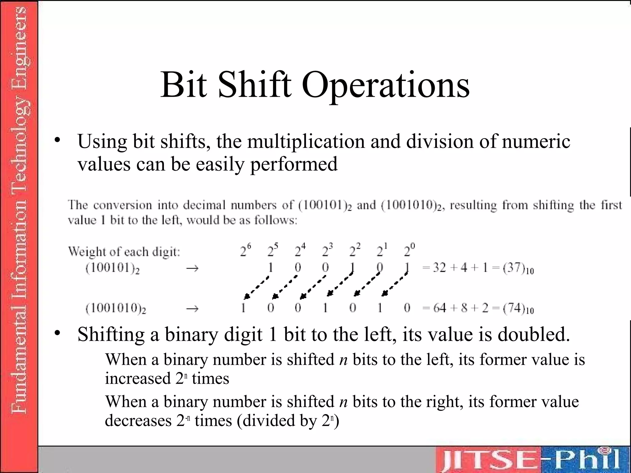
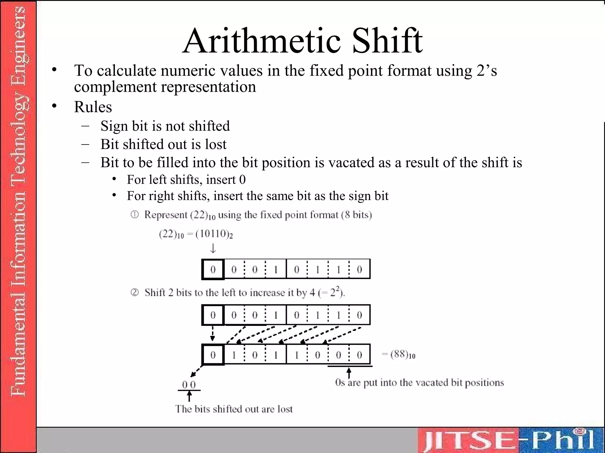
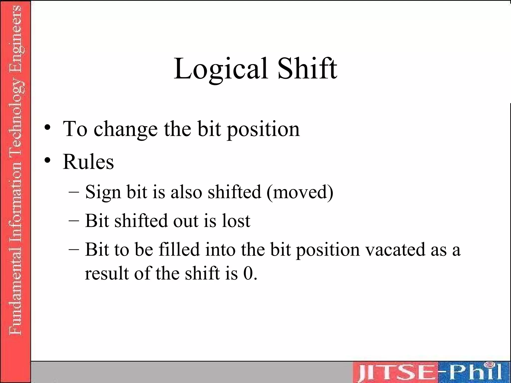
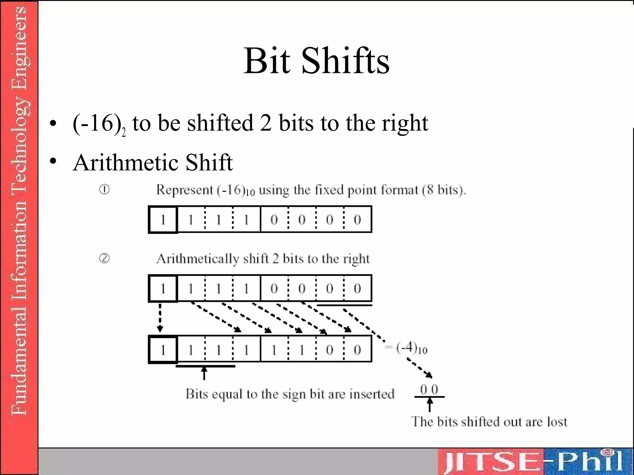
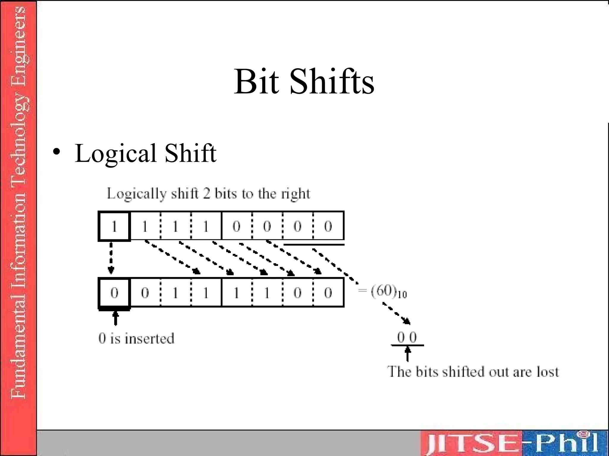
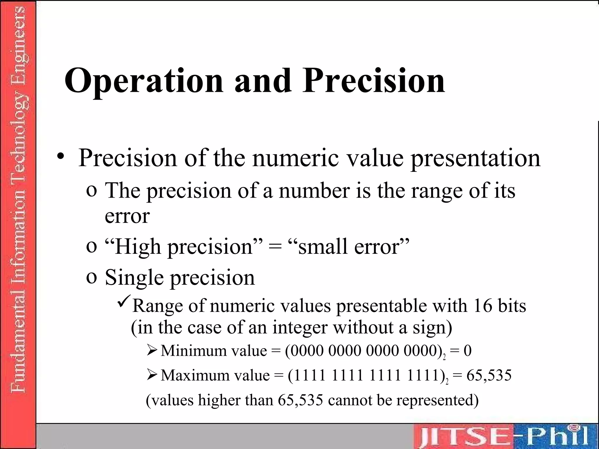
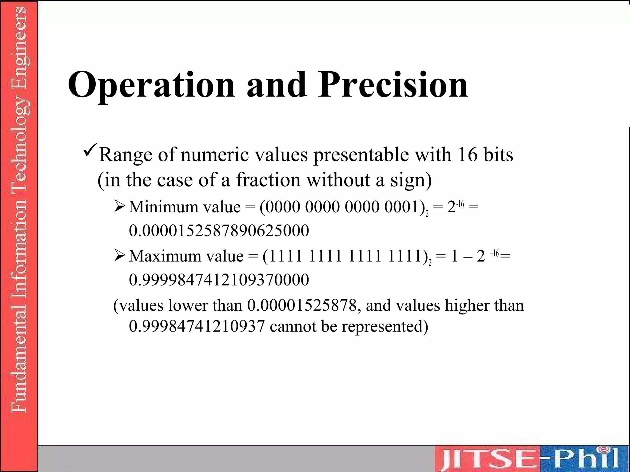
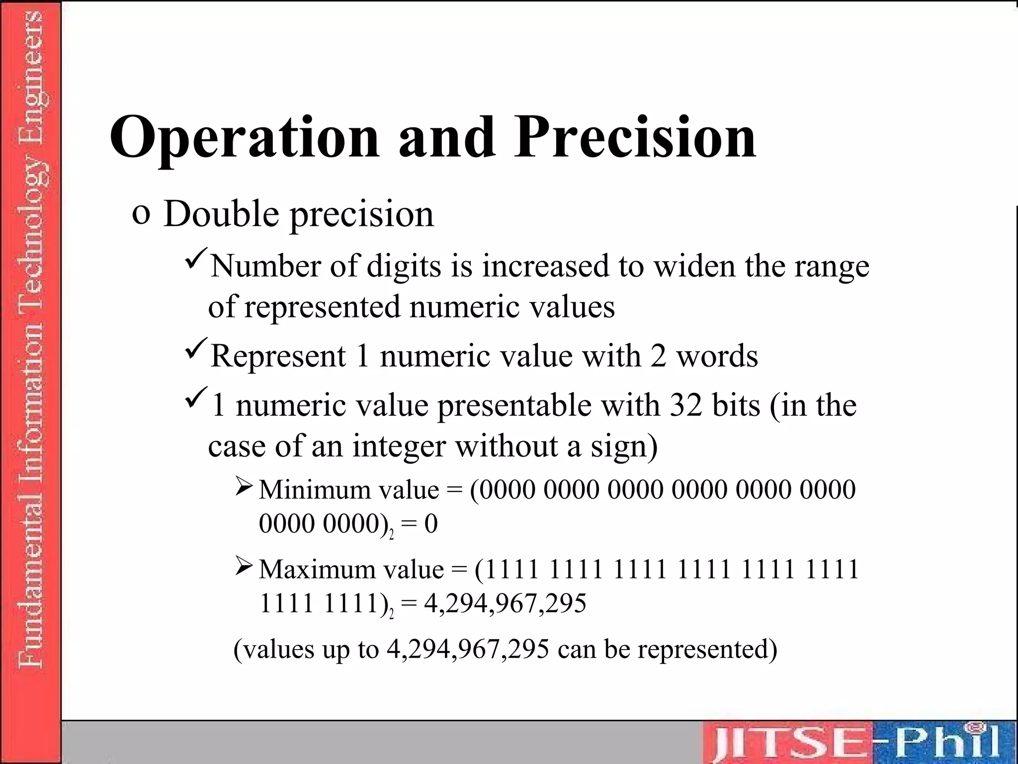
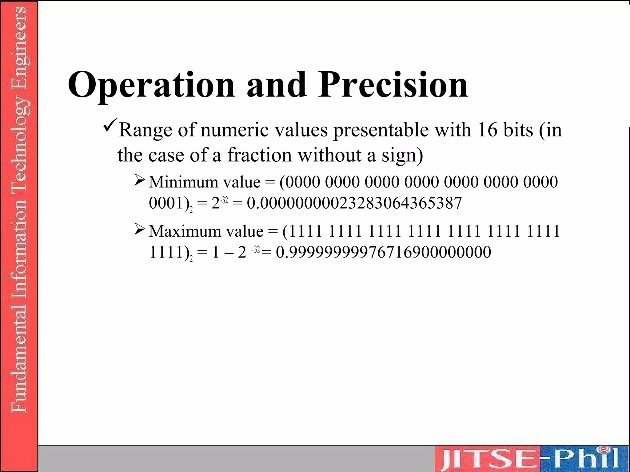
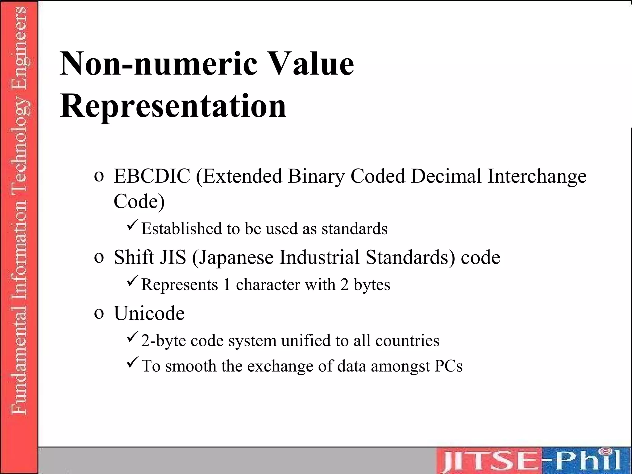
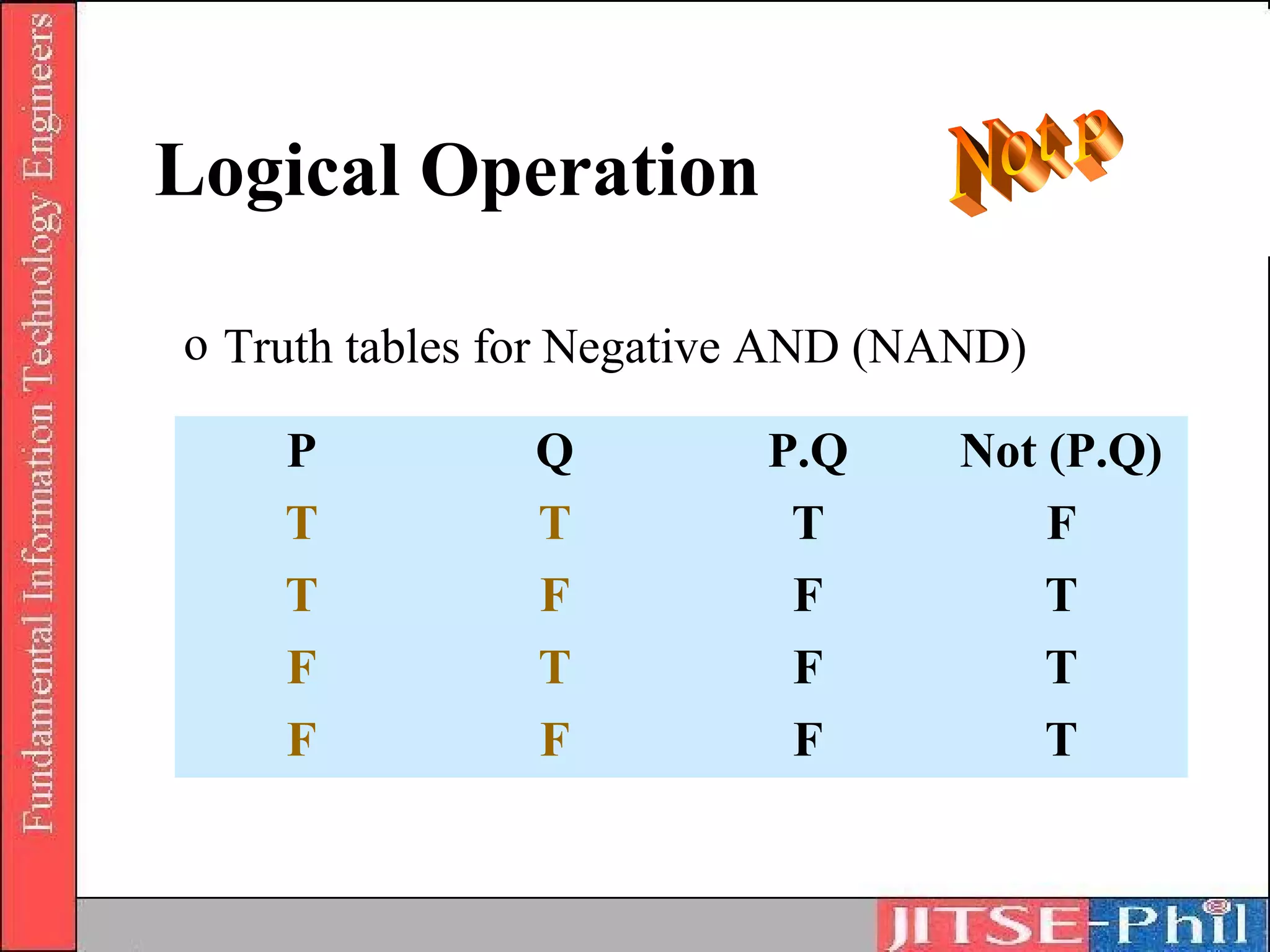
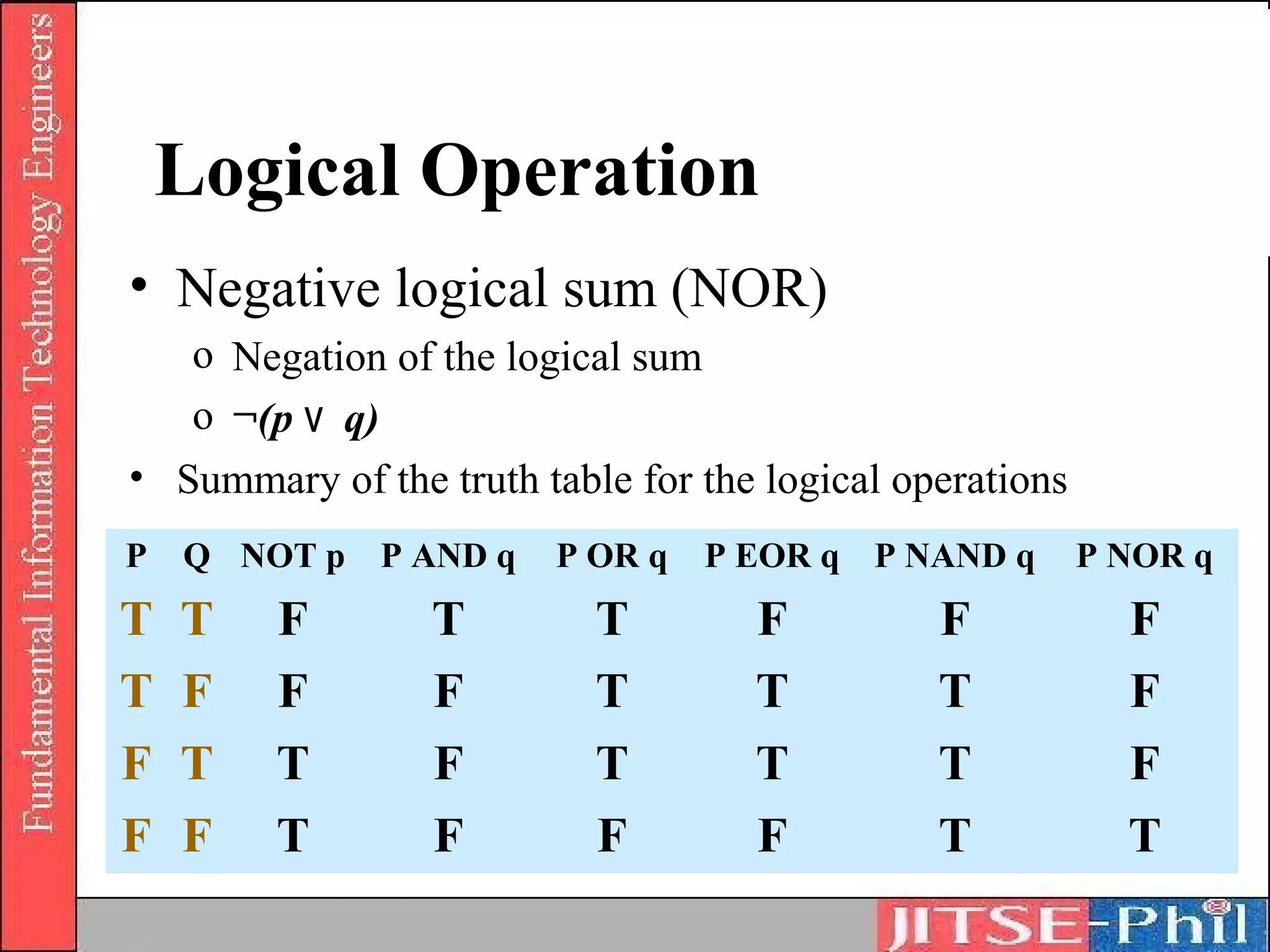
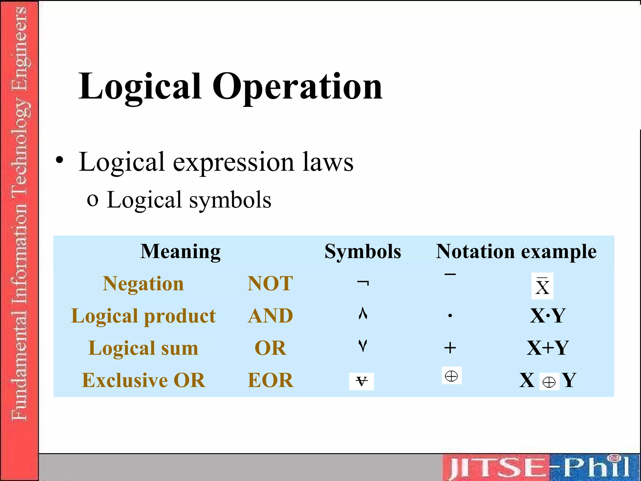
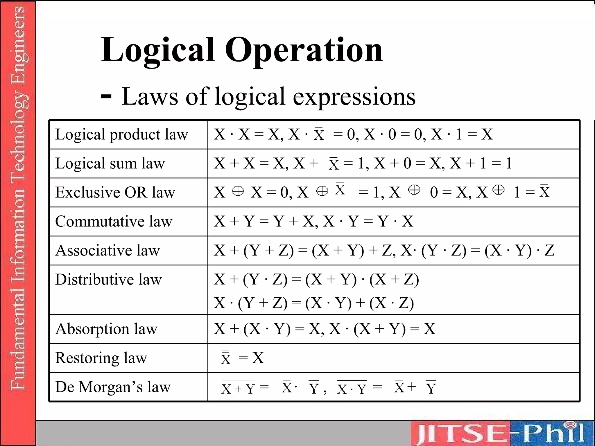
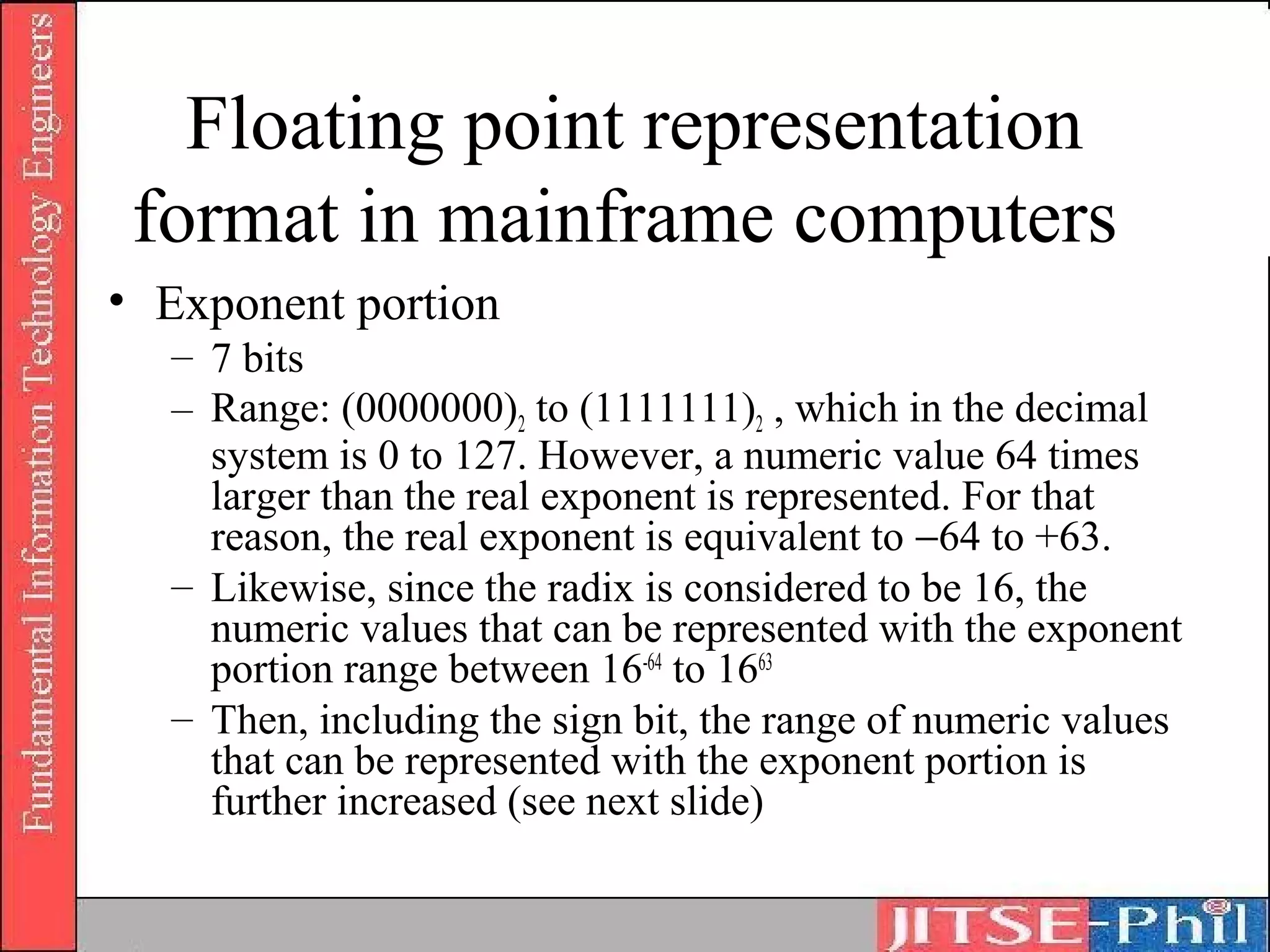
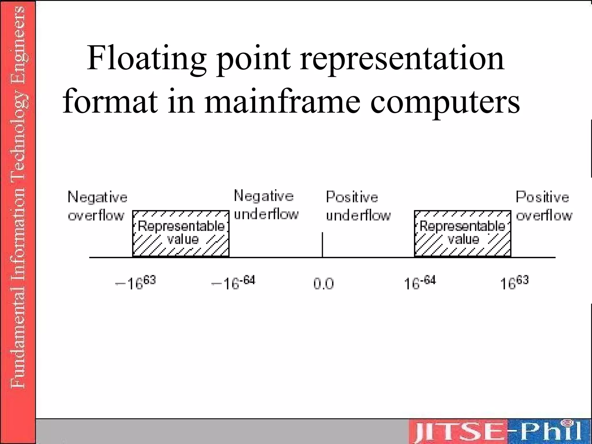
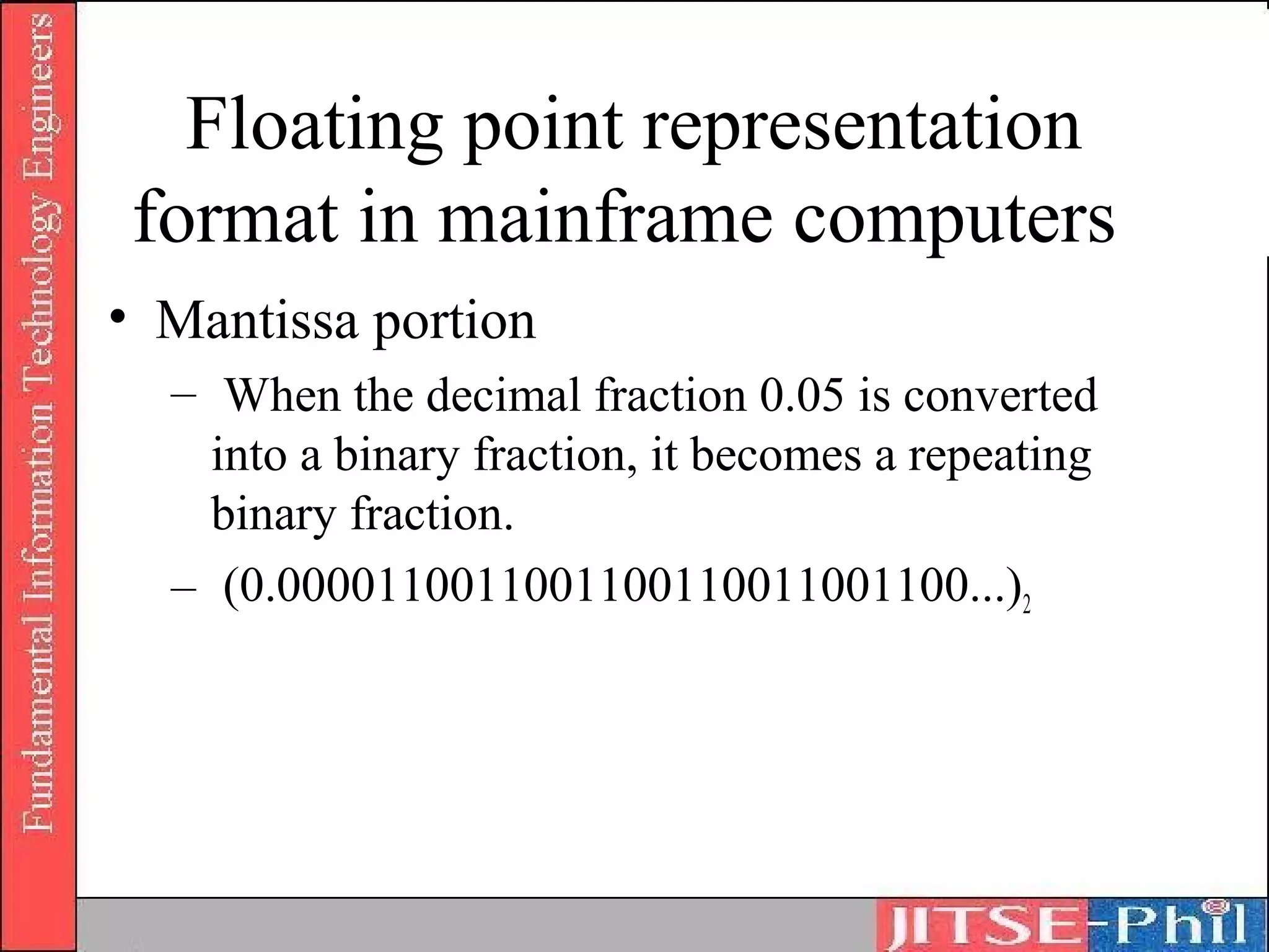
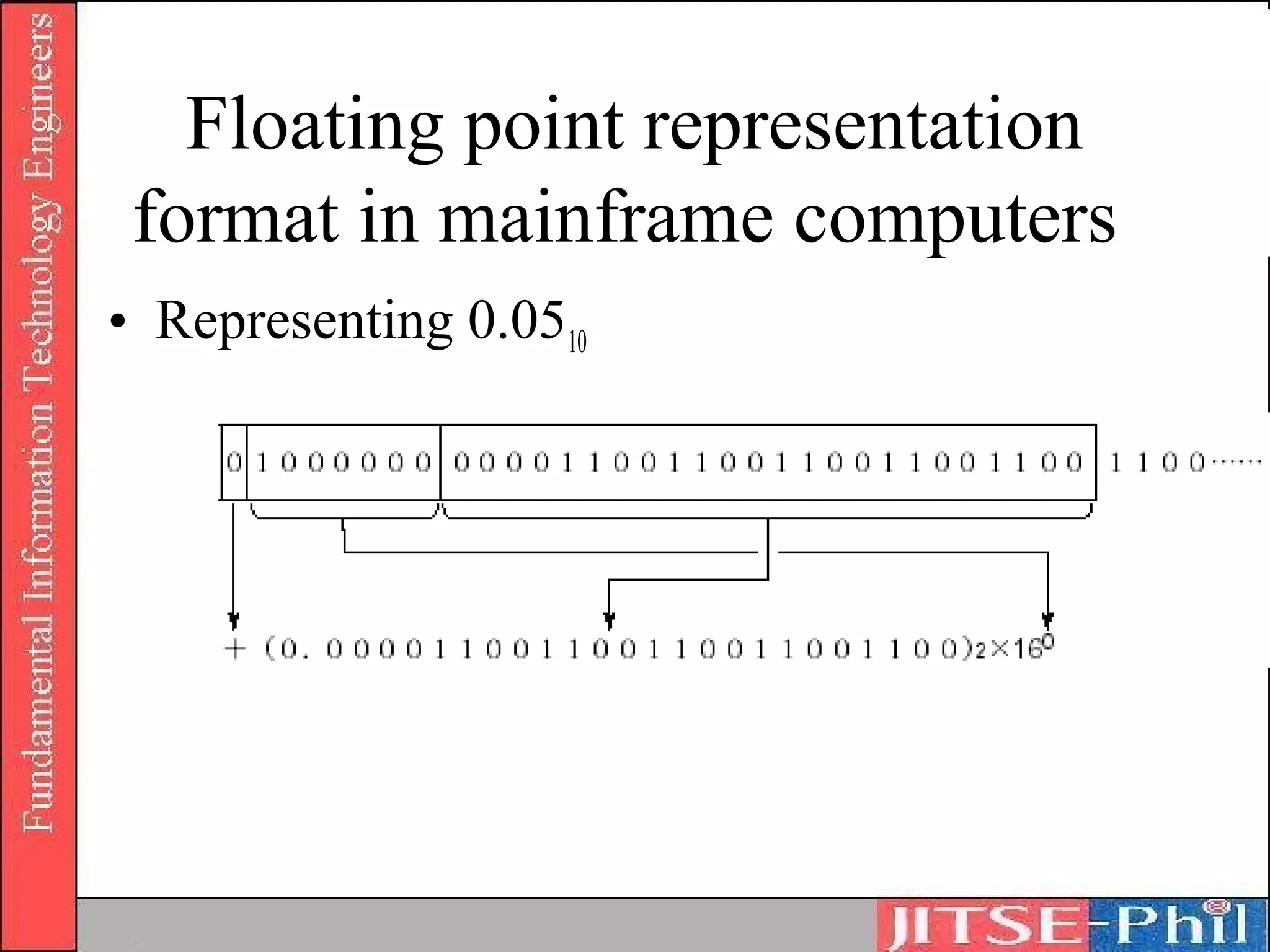
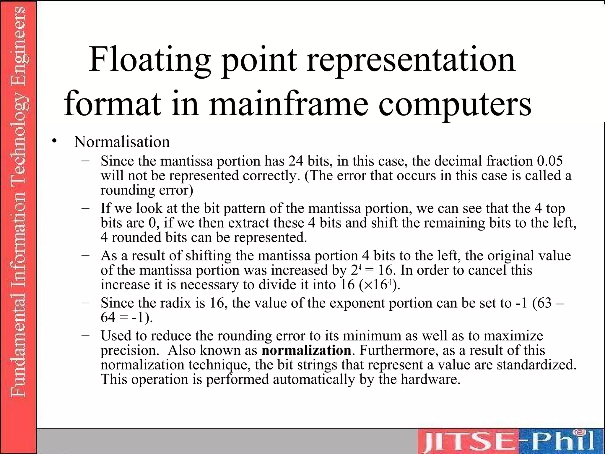
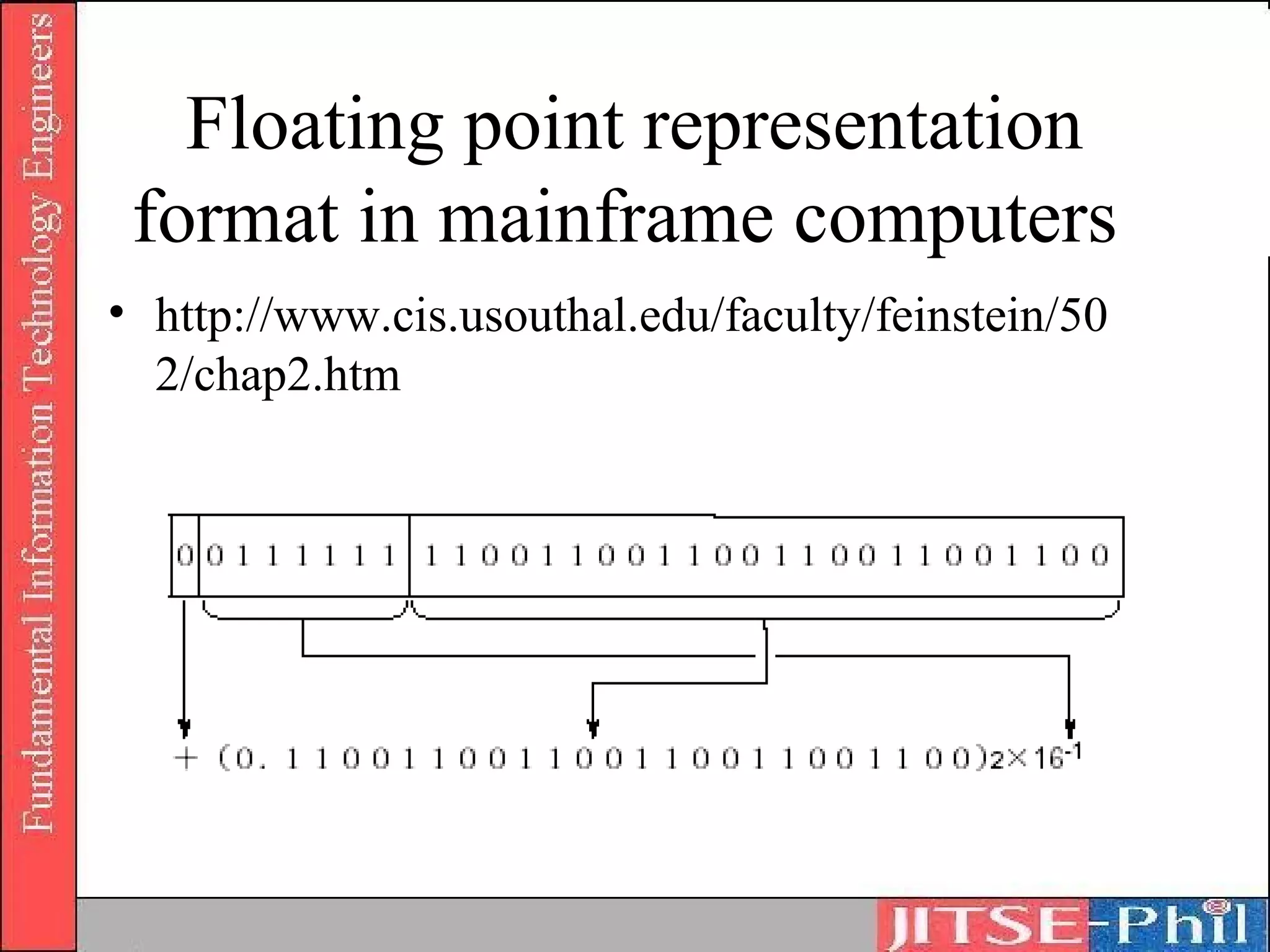
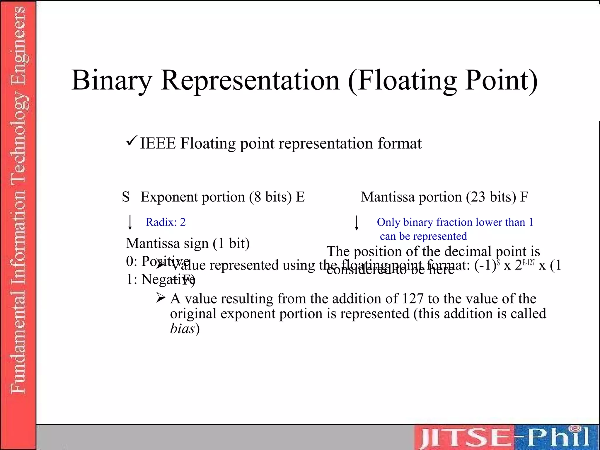
Part 1:
Computer System

Chapter 1: Basic Theories of Information
Digital Divide?
Digital Divide?
Learning Objectives
• To design and develop programs based on internal-
  design documents, and to play the following roles
  in a system development project:
   – Use basic knowledge and skills related to information
     technology in general and contributing to system
     development as a member of the project
   – Prepare program design documents based on supplied
     internal design documents, under the direction of higher-
     level engineers such as software design and development
     engineers
   – Develop programs by using knowledge related to basic-
     level algorithm and data structure
   – Making tests of the developed program
Textbooks
• Textbook for Fundamental Information
  Technology Engineers
  – No.1 Introduction to Computer Systems
Overview

     “ In order to make a computer
       work, information needs to
       be converted into a format that
       can be understood by the
       computer.”
Part 1: Computer System

 Basic Theories of Information
    (Text No. 1 Chapter 1)
Objectives
• Understanding a computer’s basic data units such
  as binary numbers, bits, bytes, words, etc. and
  their conversions from and to octal, decimal, and
  hexadecimal digits
• Understanding basic concepts of computer internal
  data representation, focusing on numeric data,
  character codes etc
• Understanding proposition calculus and logical
  operations
Some Terminology
• Data representation unit and processing unit
  1. Binary Digits (Bits)
      Two levels of status in computer’s electronic circuits
          Whether the electric current passes through it or not
          Whether the voltage is high or low
        1 digit of the binary system represented by “1” or “0”
        Smallest unit that represents data inside the computer
        1 bit can represent 2 values of data, “0” or “1”
        2 bits can represent 4 different values
           “00”, “01”, “10”, “11”
(or
Table)


(or Row)


(or Column)
Bit representation

Switches     Open (0) or closed (1)
Current      Not flowing (0) or flowing (1)

Lights       Off (0) or on (1)
Numeric Conversion
3. Bytes
    A byte is a unit that represents with 8 bits 1 character or
     number, 1 byte = 8 bits
    E.g. “00000000”, “00000010”, etc.
    1 bit can be represented in 2 ways, i.e. combination of 8 bit
     patterns into 1 byte enables the representation of 2 8 = 256
     types of information
    Using a 1-byte word, 256 different characters can be
     represented – sufficient for most Western character sets
    However, the number of kanji (Chinese characters) amounts
     to thousands of different characters, hence a 1-byte word
     system is insufficient
    Two bytes are connected to obtain 16 bits, 2 16 = 65,536
      A 2-byte word
Numeric Conversion

4. Word
    The smallest unit that represents data inside a computer
    Increase operation speed
5. Number systems
    Binary system is used to simplify the structure of electronic
     circuits that make up a computer
    Hexadecimal number is a numeric value represented by 16
     numerals from “0” to “15” to ease the representation of binary
     numbers for humans – computers are capable of only using
     binary numbers
Numeric Systems
Also known as Base Systems or Radix
 Systems
Available digits:
    Decimal system (base 10)
        0, 1, 2, 3, 4, 5, 6, 7, 8, 9
    Binary system (base 2)
        0, 1
    Octal system (base 8)
        0, 1, 2, 3, 4, 5, 6, 7
    Hexadecimal (base 16)
        0, 1, 2, 3, 4, 5, 6, 7, 8, 9, A, B, C, D, E, F
        where A=10,B=11,C=12,D=13,E=14,F=15
Numeric Data
  Representation
• The true value of numbers are the same
• The representation of numbers vary
   –   Decimal
   –   Binary
   –   Octal
   –   Hexadecimal
Numeric data representation
DECIMAL number        2            1           9          9          8
(Radix/Base = 10)
Weight                104          103        102        101        100

Value                2*104       2*103      2*102       9*101   8*100

Final (true) value          20000 + 1000 + 900 + 90 + 8 = 2199810


BINARY number         1            1           0          0          1
(Radix/Base = 2)
Weight                24           23         22          21         20
Value                1*24         1*23       0*22       0*21        0*20

Final (true) value                 16 + 8 + 0 + 0 + 1 = 252
Numeric data representation
OCTAL number         2   1   7   7    2
(Radix/Base = 8)
Weight

Value

Final (true) value


HEXA number          A   2   5   7    C
(Radix/Base = 16)
Weight

Value

Final (true) value
Binary Arithmetic
• Addition and subtraction of binary numbers
   – Addition
      •   0 + 0 = 0 (or 010)
      •   0 + 1 = 1 (or 110)
      •   1 + 0 = 1 (or 110)
      •   1 + 1 = 10 (or 210)
   – Subtraction
      •   0–0=0
      •   0 – 1 = -1
      •   1–0=1
      •   1–1=0
Binary Addition


  Result = 1001102
Binary Subtraction


    Result = 10102
Hexadecimal arithmetic
4. Addition and subtraction of hexadecimal
   numbers
    Addition
        Performed starting at the lowest (first from the
         right) digit
        A carry to the upper digit is performed when the
         result is higher than 16
    Subtraction
        Performed starting at the lowest (first from the
         right) digit
        A borrow from the upper digit is performed when
         the result is negative
Hexadecimal Addition


• First column from right
   D + 7 = (In the decimal system: 13 + 7 = 20) = 16 (carried 1) + 4
   The sum of the first column is 4 and 1 is carried to the second column.
• Second column from right
   1 + 8 + 1 = (In the decimal system: 10) = A
   Carried from the first column
• Third column from right
   A + B = (In the decimal system: 10 + 11 = 21) = 16 (carried 1) + 5
   The sum of the third column is 5 and 1 is carried to the fourth column.
• The result is (15A4)16.
Hexadecimal Subtraction


• First column from right
   Since 3 – 4 = –1, a borrow is performed from D in the second digit
      (D becomes C).
   16 (borrowed 1) + 3 – 4 = F (In the decimal system: 19 – 4 = 15)
• Second column from right
   C – 7 = 5 (In the decimal system: 12 – 7 = 5)
• Third column
   6–1=5
• The result is (55F)16.
Exercises
•    Compute the following
    a)   2710 + 1510
    b)   110112 + 11112
    c)   338 + 178
    d)   1B16 + F16


•    Compute the following
    a)   5010 – 2210
    b)   1100102 - 101102
    c)   628 – 268
    d)   3216 - 1616
Numeric data representation
                                                           Radix/Base


   300010 = 3 * 10                      3                   Exponent

• Representation of numeric data
   1. Radix and “weight”
       Decimal numbers’ “weight” and its meaning
           “10” is called “Radix”
           upper right of 10 (in this example, 4) is called “exponent”
       Binary digit’s “weight” and its meaning
   2. Auxiliary units and power representation
       Used to represent big, small amounts, and exponent to which the
        radix is raised
Radix/Base Conversion
•   In order to process numeric values in a computer, decimal
    numbers are converted into binary or hexadecimal numbers
•   However, since we ordinarily use decimal numbers, it
    would be difficult to understand the meaning of the result of
    a process if it were represented by binary or hexadecimal
    numbers.
•   This operation is called radix conversion
•   The following radix/base conversion techniques will be
    discussed:
      1.   Decimal to Binary
      2.   Binary to Decimal
      3.   Binary to Hexadecimal
      4.   Hexadecimal to Binary
      5.   Octal to Binary
      6.   Binary to Octal
1. Decimal to Binary (Integer)
1. Decimal integer is divided into 2
2. The quotient and remainder are obtained
3. The quotient is divided into 2 again until
   the quotient becomes 0
4. The binary value is obtained by placing
   the remainder(s) in reverse order
1. Decimal to Binary (Integer)
1. Decimal to Binary (Fraction)
• Decimal fraction is multiplied by 2
   – Resulting integer portion is extracted (always be “0” or “1”)
   – Resulting fraction portion is multiplied by 2
   – Operation is repeated until the fraction portion becomes 0
• When decimal fractions are converted into binary
  fractions, most of the times, the conversion is not finished,
  since no matter how many times the fraction portion is
  multiplied by 2, it will not become 0. Most decimal
  fractions become infinite binary fractions.
1. Decimal to Binary (Fraction)
2. Binary to Decimal (Integer)
• Performed by adding up the weights of each of the
  digits of the binary bit string
2. Binary to Decimal (Fraction)
• Same technique as for binary integers.
3. Binary to Hexadecimal
• 4-bit binary strings are equivalent to 1
  hexadecimal digit
• The binary number is divided into groups of
  4 digits starting from the decimal point
• In the event that there is a bit string with
  less than 4 digits, the necessary number of
  0’s is added and the string is considered as a
  4-bit string
3. Binary to Hexadecimal (Integer)
3. Binary to Hexadecimal (Fraction)
4. Hexadecimal to Binary (Integer)
• 1 digit of the hexadecimal number is represented
  with a 4-digit binary number
4. Hexadecimal to Binary (Fraction)
• Same technique as per integer
5. Octal to Binary
• Convert 1038 to its binary form
6. Binary to Octal
• Convert 10000112 to Octal
Exercises
•    Convert into binary, octal and hexa
    a) 2710
    b) 1510
    c) 50.2210
•    Convert into decimal
    a) 110112
    b) 338
    c) 1B.F16
Octal-Binary Conversions
• Binary to/from Octal conversion
   – Conversion of binary to/from octal (whole numbers)
   – Conversion of octal fractions
       • In decimal, 26.9210 = (2 * 101) + (6 * 100) + (9 * 10-1) + (2 * 10-2)
       • 0.48 means 4 * 8-1 = (4/8) 10 = ½10 = 0.510
       • 0.2118 means (2 * 8-1) + (1 * 8-2) + (1 * 8-3)
   – Conversion of binary fractions
       • Binary fractions can be converted in a similar manner to octal as that
         of octal fractions
       • The number can then be converted to decimal by adding up the whole
         numbers and convert the fractions to decimals
Quiz
•    Try this…
    A. What number does the next digit position represent in
       the hexadecimal system?

       ?         ?         256      16        1
    B. Use the answer to evaluate the decimal equivalent of
       2A9D16
    C. What is the highest decimal number which may be
       represented by four hexadecimal digits?
    D. What is the highest decimal number which may be
       represented by four octal digits?
Numeric Presentation

                             Fixed Point (Integers)
                   Binary
       Numeric     Numbers
                             Floating Point (Real Numbers)
        Data
Data
       Character             Unpacked Decimal
         Data      Decimal                            Represented
                   Numbers                            using
                             Packed Decimal           decimal
                                                      arithmetic
Decimal digit representation
• Binary coded decimal
• Unpacked decimal format
• Packed decimal format
Decimal digit representation
o Binary-coded decimal (BCD) code
    Uses 4-bit binary digits (correspond to numbers 0 to 9 of decimal
     system)
Decimal digit representation
• BCD code
• Example:
Decimal digit representation
– Unpacked decimal format
   • Uses 1 byte for each digit of decimal number
   • Represents values from 0 to 9 in least significant 4 bits of 1
     byte and in most significant 4 bits (zone bits)
   • Half of a byte is used (excepting the least significant byte) –
     where the least significant half-byte is used to store the sign
       – 1100 = +ve
       – 1101 = -ve
   • Waste of resources (eliminated by packed decimal format)
Decimal digit representation
• Unpacked decimal format


                            +78910 = F7F8C916


                            -78910 = F7F8D916
Decimal digit representation
o Packed decimal format
    1 byte represents a numeric value of 2 digits
    the least significant 4 bits represent the sign
    bit pattern for the sign is the same as per unpacked decimal
     format


                                             +78910 = 789C16


                                             -78910 = 789D16
Questions
• A) Represent 7089310
   – in Unpacked Decimal Format
   – in Packed Decimal Format
• B) Represent 789310
   – in Unpacked Decimal Format
   – in Packed Decimal Format
• C) F3F9C116 is represented in standard Unpacked Decimal
  Format
   – What is its equivalent in decimal?
   – Possible solution?
• D) 3F9C16 is represented in standard Packed Decimal
  Format
   – What is its equivalent in decimal?
   – Possible solution?
Decimal digit representation
o Packed decimal format versus Unpacked
  decimal format
  A numeric value can be represented by fewer bytes
  The conversion into the binary system is easy
Binary Representation
• Representation of negative integers
     Absolute value representation
         “0” for positive, “1” for negative
     Complement representation
         Decimal complement
            9’s complement
            10’s complement
         Binary complement
            1’s complement
            2’s complement
Binary Representation
• Absolute value representation
  – Examples
      • (00001100)2 = (+12)10
      • (10001100)2 = (-12)10
  – Issues
      • (00000000)2 = +0
      • (10000000)2 = -0
  – Range of values (assumption: 7-bit absolute value representation used)
      • -63 to +63 equivalent to –(26-1) to +(26-1)
Binary Representation
• Complement
  representation of
  negative numbers
   – Decimal complement
   – The subtraction of each
     of the digits of a
     numeric value from the
     complement
Binary Representation
• Binary complement
   – 1’s complement of a given numeric value is the result of the
     subtraction of each of the digits of this numeric value from 1, as a
     result, all the “0” and “1” bits of the original bit string are switched.
Binary Representation
• Binary complement
   – 2’s complement is “1’s complement” + 1
Binary Representation
• 1’s complement and 2’s complement
  representation of negative numbers
Binary Representation
• Advantages of 2’s complement
   – Less complicated (only one zero value)
   – Range of values to be represented is wider
   – Subtractions can be performed with addition circuits, simplifying
     hardware structure
Binary Representation
• “1’s complement” and “2’s complement”
  representation of negative integers
   – range of represented numeric values when n-bit binary
     number is represented by adopting the “1’s complement”
     method:
               -(2n-1 – 1) to (2n-1 – 1)
   – range of represented numeric values when n-bit binary
     number is represented by adopting the “2’s complement”
     method:
               -(2n-1) to (2n-1 – 1)
Binary Representation
• Addition circuits only
Binary Representation (Fixed Point)
 – Fixed point
    • Integer representation
       – Fixed point is a data representation format used mainly
         when integer type data is processed
       – One word is represented in a fixed length (e.g. 16 bits and
         32 bits)
       – Overflow problem when attempt is made to represent a
         numeric value that exceeds the fixed length allocated
    • Fraction representation
       – Decimal point is considered to be immediately preceded
         by the sign bit
Binary Representation (Fixed Point)
 – Fixed point
    • Integer representation
    • Range of values
       -(2n-1) to (2n-1 – 1)
Binary Presentation (Fixed Point)
 – Fixed point
    • Fraction representation
Binary Representation (Floating Point)
– Floating point
   • Used to represent real
     number type data
   • Used to represent
     extremely large or small
     size of data
Bit Shift Operations
• Using bit shifts, the multiplication and division of numeric
  values can be easily performed


• Shifting a binary digit 1 bit to the left, its value is doubled.
      When a binary number is shifted n bits to the left, its former value is
      increased 2n times
      When a binary number is shifted n bits to the right, its former value
      decreases 2-n times (divided by 2n)
Arithmetic Shift
•   To calculate numeric values in the fixed point format using 2’s
    complement representation
•   Rules
     – Sign bit is not shifted
     – Bit shifted out is lost
     – Bit to be filled into the bit position is vacated as a result of the shift is
          • For left shifts, insert 0
          • For right shifts, insert the same bit as the sign bit
Logical Shift
• To change the bit position
• Rules
  – Sign bit is also shifted (moved)
  – Bit shifted out is lost
  – Bit to be filled into the bit position vacated as a
    result of the shift is 0.
Bit Shifts
• (-16)2 to be shifted 2 bits to the right
• Arithmetic Shift
Bit Shifts
• Logical Shift
Operation and Precision
• Precision of the numeric value presentation
  o The precision of a number is the range of its
    error
  o “High precision” = “small error”
  o Single precision
     Range of numeric values presentable with 16 bits
      (in the case of an integer without a sign)
         Minimum value = (0000 0000 0000 0000) 2 = 0
         Maximum value = (1111 1111 1111 1111)2 = 65,535
        (values higher than 65,535 cannot be represented)
Operation and Precision
Range of numeric values presentable with 16 bits
 (in the case of a fraction without a sign)
    Minimum value = (0000 0000 0000 0001) 2 = 2-16 =
     0.0000152587890625000
    Maximum value = (1111 1111 1111 1111)2 = 1 – 2 –16 =
     0.9999847412109370000
   (values lower than 0.00001525878, and values higher than
     0.99984741210937 cannot be represented)
Operation and Precision
o Double precision
   Number of digits is increased to widen the range
    of represented numeric values
   Represent 1 numeric value with 2 words
   1 numeric value presentable with 32 bits (in the
    case of an integer without a sign)
       Minimum value = (0000 0000 0000 0000 0000 0000
        0000 0000)2 = 0
       Maximum value = (1111 1111 1111 1111 1111 1111
        1111 1111)2 = 4,294,967,295
      (values up to 4,294,967,295 can be represented)
Operation and Precision
 Range of numeric values presentable with 16 bits (in
  the case of a fraction without a sign)
     Minimum value = (0000 0000 0000 0000 0000 0000 0000
      0001)2 = 2-32 = 0.00000000023283064365387
     Maximum value = (1111 1111 1111 1111 1111 1111 1111
      1111)2 = 1 – 2 –32 = 0.99999999976716900000000
Operation and Precision
• Operation precision
   o Precision of fixed point representation
       Range of presentable numeric values depends on the computer
        hardware (number of bits in one word)
       Range of represented numeric values differs depending on the number
        of bits in one word
       Step size of the integer part is always 1 (regardless of number of bits),
        and only the maximum value changes
       In the fraction part, the smaller the step size becomes, the error is also
        reduced
   o Precision and underflow
       Overflow and underflow
           Overflow occurs when product is higher than the maximum value that
            can be represented with the exponent portion (Maximum absolute value
            < Overflow)
           Underflow occurs when product is lower than the minimum absolute
            value (0 < Underflow < Minimum absolute value)
Operation and Precision
  Cancellation
      When subtraction of 2 floating point numbers of almost
       equal values is performed
      Result becomes extremely small, it is left out of the range
       of numeric values which can be represented
  Loss of information
      Addition of extremely small value and extremely large
       value is performed
      Exponents adjusted to the exponent of the largest value
       (mantissa portion of the small value is shifted largely to
       the right), leading to the loss of information that should
       have been presented
Non-numeric Value Representation
• In order to represent characters using binary digits, codes are
  used
   – ASCII, ANSI, UNICode
• Character Representation
   – Numeric keys:              0 to 9  10 types
   – Character keys:    Uppercase: A to Z
                        Lower case: a to z  52 types
   – Symbolic keys:             40 types
   – Control character keys:    34 types (Space key etc)
• To assign a unique bit pattern corresponding to these 136
  types of characters and symbols, 256 types of bit patterns i.e.
  8 bits are used.
Non-numeric Value
Representation
 • Character codes
   o ASCII (American Standard Code for Information
     Interchange) code
       Character code of 8 bits (alphabet, numeric characters, etc.)
       Used in PCs and data transmission
   o ISO (International Organization for Standardization)
     code
       7-bit character code
       Base of the character codes used in all countries of the world
   o JIS (Japanese Industrial Standard) code
       Represents 1 character with 2 bytes (16 bits)
Non-numeric Value
Representation
 o EBCDIC (Extended Binary Coded Decimal Interchange
   Code)
     Established to be used as standards
 o Shift JIS (Japanese Industrial Standards) code
     Represents 1 character with 2 bytes
 o Unicode
     2-byte code system unified to all countries
     To smooth the exchange of data amongst PCs
Non-numeric Value Representation
• Audio representation
   o Multimedia audio
   o Audio analysis is performed using a numeric formula and once it is
     converted into digital codes it is processed in the computer.
   o Word processors that accept audio input and speaker recognition are
     examples of its recent applications.
• Image representation
   o Image data must be processed to support current multimedia
   o Image data is processed as a set of dots
   o Example
       o 1 bit is used to register the information of each dot (black, white)
       o The representation method that combines the basic colors in each dot
         is used. Systems that combine the three primary colors (Red, Green
         and Blue) in 256 levels respectively and represent approximately
         16,000,000 colors. In this case, since 8 bits are needed for 1 color, in
         order to register the information of 1 dot, 24 bits are used.
Information and Logic


      • Proposition Logic
      • Logical operation
Proposition Logic
• A proposition is an assertion that something is the
  case. We use sentences to express propositions.
• Examples:
  (i) The following sentences express the same
      proposition:
        - “It is raining”
  (ii) The following sentences express the same
      proposition:
        - “John loves Mary”
        - “Mary is loved by John”
Proposition Logic
• Proposition will always be either “true” or “false”
• Philosophers argue a lot about what constitutes
  truth. For now, we'll keep it simple:
   o "P" is true if and only if P.
   o "P" is false if and only if not P.
• Examples:
  (i) The proposition "Snow is white" is true if and
       only if snow is white.
  (ii) The proposition "Snow is white" is false if
       and only if snow is not white.
Proposition Logic
• Truth table
  Proposition 1         Proposition 2 “If the wind
  “The wind is blowing” “It is raining” blows it rains”
  True                   True            True
  True                   False           False
  False                  True            False
  False                  False           False
Proposition Logic
• Examples
     p       q
     T       T
     T       F   p   q   p and q
     F       T   T   T      T
     F       F   T   F      F
                 F   T      F
                 F   F      F
Logical Operation
• A logical operator joins two propositions to
  form a new, complex, proposition.
• The truth value of the new proposition is
  determined by the truth values of the two
  propositions being joined and by the
  operator that joins them.
Logical Operation

• Negation
  o Any proposition p can be converted into its
    negation with a negation operator, producing
    the new, complex, proposition:
     ¬p means Not p
     The proposition Not p is true if and only if p is false
     It is false only if p is true
Logical Operation
o Truth tables for Negation
      p        ¬p
      T        F
      F        T       p      q   Not p
                       T      T    F
                       T      F    F
                       F      T    T
                       F      F    T
Logical Operation
• Logical Product
  o Any two propositions p and q can be connected
    with the conjunction “AND”, producing the
    new, complex, proposition:
     p and q (p ٨ q)
     The proposition p and q is true if and only if both p
      and q are true
     It is false otherwise
Logical Operation

o Truth tables for Logical product

        p          q       p٨ q
        T          T        T
        T          F        F
        F          T        F
        F          F        F
Logical Operation
• Logical Sum
  o Any two propositions p and q can be connected
    with the conjunction “OR”, producing the new,
    complex, proposition:
     p or q (p ۷ q)
     The proposition p and q is true if and only if either
      p or q are true
     It is false only if both p and q are false
Logical Operation
o Truth tables for Logical sum
        p         q        p۷q
        T         T         T
        T         F         T
        F         T         T
        F         F         F
Logical Operation
• Exclusive OR
  o Any two propositions p and q can be
    connected with the conjunction “EOR”,
    producing the new, complex, proposition:
     p eor q (p     q)
     The proposition p eor q is true only if when p or q
      is true
     It is false when both p and q are true or false
Logical Operation
o Truth tables for Exclusive OR
        p         q       p       q
        T         T           F
        T         F           T
        F         T           T
        F         F           F
Logical Operation
• Negative AND (NAND)
  o Any proposition p can be converted into its
    negation with a negation operator, producing
    the new, complex, proposition:
     Not p
     The proposition Not p is true if and only if p is false
     It is false only if p is true
Logical Operation

o Truth tables for Negative AND (NAND)

    P          Q          P.Q     Not (P.Q)
    T          T           T          F
    T          F           F          T
    F          T           F          T
    F          F           F          T
Logical Operation
• Negative logical sum (NOR)
   o Negation of the logical sum
   o ¬(p ۷ q)
• Summary of the truth table for the logical operations
P   Q NOT p P AND q      P OR q   P EOR q P NAND q        P NOR q
T   T   F        T         T        F          F            F
T   F   F        F         T        T          T            F
F   T   T        F         T        T          T            F
F   F   T        F         F        F          T            T
Logical Operation
• Logical expression laws
  o Logical symbols

        Meaning          Symbols   Notation example
    Negation       NOT      ¬      ¯
 Logical product   AND      ٨       ·       X·Y
  Logical sum      OR       ۷      +        X+Y
  Exclusive OR     EOR                     X   Y
Logical Operation
      - Laws of logical expressions
Logical product law   X · X = X, X ·       = 0, X · 0 = 0, X · 1 = X
Logical sum law       X + X = X, X +        = 1, X + 0 = X, X + 1 = 1
Exclusive OR law      X    X = 0, X           = 1, X       0 = X, X    1=
Commutative law       X + Y = Y + X, X · Y = Y · X
Associative law       X + (Y + Z) = (X + Y) + Z, X· (Y · Z) = (X · Y) · Z
Distributive law      X + (Y · Z) = (X + Y) · (X + Z)
                      X · (Y + Z) = (X · Y) + (X · Z)
Absorption law        X + (X · Y) = X, X · (X + Y) = X
Restoring law             =X
De Morgan’s law             =     ·    ,         =     +
Exercises
• Use the Laws of Logical Propositions to
  simplify each of the propositions below to
  one of the propositions F, T, p, q, p.q, p+q
  a) p + q + -p
  b) p + (q + p) + -q
Where to Get More Information
• Truth table practice:
  http://www.math.csusb.edu/notes/quizzes/tablequi
  z/tablepractice.html
• Digital Logic : Operation and
  Analysis
  by Jefferson C. Boyce
• Digital Logic and Switching
  Circuits : Operation and Analysis
  by Jefferson C. Boyce
Topics
• Floating point representation format
   – Excess 64
   – IEEE
• Data Structures
   – Basic data structure
      • Basic data type
      • Structured data type
      • Abstract data type
   – Problem-oriented data structure
      •   List
      •   Stack
      •   Queue
      •   Tree
      •   Hash
Floating point representation
 format in mainframe computers
• This format was adopted in the first general-purpose
  computer in the world the "IBM System/360" and it was
  called Excess 64.
Floating point representation
 format in mainframe computers
• Exponent portion
  – 7 bits
  – Range: (0000000)2 to (1111111)2 , which in the decimal
    system is 0 to 127. However, a numeric value 64 times
    larger than the real exponent is represented. For that
    reason, the real exponent is equivalent to −64 to +63.
  – Likewise, since the radix is considered to be 16, the
    numeric values that can be represented with the exponent
    portion range between 16-64 to 1663
  – Then, including the sign bit, the range of numeric values
    that can be represented with the exponent portion is
    further increased (see next slide)
Floating point representation
format in mainframe computers
Floating point representation
 format in mainframe computers
• Mantissa portion
  – When the decimal fraction 0.05 is converted
    into a binary fraction, it becomes a repeating
    binary fraction.
  – (0.0000110011001100110011001100...)2
Floating point representation
 format in mainframe computers
• Representing 0.0510
Floating point representation
 format in mainframe computers
• Normalisation
   – Since the mantissa portion has 24 bits, in this case, the decimal fraction 0.05
     will not be represented correctly. (The error that occurs in this case is called a
     rounding error)
   – If we look at the bit pattern of the mantissa portion, we can see that the 4 top
     bits are 0, if we then extract these 4 bits and shift the remaining bits to the left,
     4 rounded bits can be represented.
   – As a result of shifting the mantissa portion 4 bits to the left, the original value
     of the mantissa portion was increased by 24 = 16. In order to cancel this
     increase it is necessary to divide it into 16 (×16-1).
   – Since the radix is 16, the value of the exponent portion can be set to -1 (63 –
     64 = -1).
   – Used to reduce the rounding error to its minimum as well as to maximize
     precision. Also known as normalization. Furthermore, as a result of this
     normalization technique, the bit strings that represent a value are standardized.
     This operation is performed automatically by the hardware.
Floating point representation
 format in mainframe computers
• http://www.cis.usouthal.edu/faculty/feinstein/50
  2/chap2.htm
Binary Representation (Floating Point)
     IEEE Floating point representation format


    S Exponent portion (8 bits) E           Mantissa portion (23 bits) F
       Radix: 2                                Only binary fraction lower than 1
                                               can be represented
    Mantissa sign (1 bit)
                                      The position of the decimal point is
    0: Positive represented using the floating point format: (-1)S x 2E-127 x (1
          Value                      considered to be here
    1: Negative
            + F)
          A value resulting from the addition of 127 to the value of the
            original exponent portion is represented (this addition is called
            bias)

1. basic theories of information

  • 1.
    Part 1: Computer System Chapter1: Basic Theories of Information
  • 2.
  • 3.
  • 4.
    Learning Objectives • Todesign and develop programs based on internal- design documents, and to play the following roles in a system development project: – Use basic knowledge and skills related to information technology in general and contributing to system development as a member of the project – Prepare program design documents based on supplied internal design documents, under the direction of higher- level engineers such as software design and development engineers – Develop programs by using knowledge related to basic- level algorithm and data structure – Making tests of the developed program
  • 5.
    Textbooks • Textbook forFundamental Information Technology Engineers – No.1 Introduction to Computer Systems
  • 6.
    Overview “ In order to make a computer work, information needs to be converted into a format that can be understood by the computer.”
  • 7.
    Part 1: ComputerSystem Basic Theories of Information (Text No. 1 Chapter 1)
  • 8.
    Objectives • Understanding acomputer’s basic data units such as binary numbers, bits, bytes, words, etc. and their conversions from and to octal, decimal, and hexadecimal digits • Understanding basic concepts of computer internal data representation, focusing on numeric data, character codes etc • Understanding proposition calculus and logical operations
  • 9.
    Some Terminology • Datarepresentation unit and processing unit 1. Binary Digits (Bits)  Two levels of status in computer’s electronic circuits  Whether the electric current passes through it or not  Whether the voltage is high or low  1 digit of the binary system represented by “1” or “0”  Smallest unit that represents data inside the computer  1 bit can represent 2 values of data, “0” or “1”  2 bits can represent 4 different values  “00”, “01”, “10”, “11”
  • 10.
  • 11.
    Bit representation Switches Open (0) or closed (1) Current Not flowing (0) or flowing (1) Lights Off (0) or on (1)
  • 12.
    Numeric Conversion 3. Bytes  A byte is a unit that represents with 8 bits 1 character or number, 1 byte = 8 bits  E.g. “00000000”, “00000010”, etc.  1 bit can be represented in 2 ways, i.e. combination of 8 bit patterns into 1 byte enables the representation of 2 8 = 256 types of information  Using a 1-byte word, 256 different characters can be represented – sufficient for most Western character sets  However, the number of kanji (Chinese characters) amounts to thousands of different characters, hence a 1-byte word system is insufficient  Two bytes are connected to obtain 16 bits, 2 16 = 65,536  A 2-byte word
  • 13.
    Numeric Conversion 4. Word  The smallest unit that represents data inside a computer  Increase operation speed 5. Number systems  Binary system is used to simplify the structure of electronic circuits that make up a computer  Hexadecimal number is a numeric value represented by 16 numerals from “0” to “15” to ease the representation of binary numbers for humans – computers are capable of only using binary numbers
  • 14.
    Numeric Systems Also knownas Base Systems or Radix Systems Available digits: Decimal system (base 10)  0, 1, 2, 3, 4, 5, 6, 7, 8, 9 Binary system (base 2)  0, 1 Octal system (base 8)  0, 1, 2, 3, 4, 5, 6, 7 Hexadecimal (base 16)  0, 1, 2, 3, 4, 5, 6, 7, 8, 9, A, B, C, D, E, F  where A=10,B=11,C=12,D=13,E=14,F=15
  • 15.
    Numeric Data Representation • The true value of numbers are the same • The representation of numbers vary – Decimal – Binary – Octal – Hexadecimal
  • 16.
    Numeric data representation DECIMALnumber 2 1 9 9 8 (Radix/Base = 10) Weight 104 103 102 101 100 Value 2*104 2*103 2*102 9*101 8*100 Final (true) value 20000 + 1000 + 900 + 90 + 8 = 2199810 BINARY number 1 1 0 0 1 (Radix/Base = 2) Weight 24 23 22 21 20 Value 1*24 1*23 0*22 0*21 0*20 Final (true) value 16 + 8 + 0 + 0 + 1 = 252
  • 17.
    Numeric data representation OCTALnumber 2 1 7 7 2 (Radix/Base = 8) Weight Value Final (true) value HEXA number A 2 5 7 C (Radix/Base = 16) Weight Value Final (true) value
  • 18.
    Binary Arithmetic • Additionand subtraction of binary numbers – Addition • 0 + 0 = 0 (or 010) • 0 + 1 = 1 (or 110) • 1 + 0 = 1 (or 110) • 1 + 1 = 10 (or 210) – Subtraction • 0–0=0 • 0 – 1 = -1 • 1–0=1 • 1–1=0
  • 19.
    Binary Addition Result = 1001102
  • 20.
    Binary Subtraction Result = 10102
  • 21.
    Hexadecimal arithmetic 4. Additionand subtraction of hexadecimal numbers  Addition  Performed starting at the lowest (first from the right) digit  A carry to the upper digit is performed when the result is higher than 16  Subtraction  Performed starting at the lowest (first from the right) digit  A borrow from the upper digit is performed when the result is negative
  • 22.
    Hexadecimal Addition • Firstcolumn from right D + 7 = (In the decimal system: 13 + 7 = 20) = 16 (carried 1) + 4 The sum of the first column is 4 and 1 is carried to the second column. • Second column from right 1 + 8 + 1 = (In the decimal system: 10) = A Carried from the first column • Third column from right A + B = (In the decimal system: 10 + 11 = 21) = 16 (carried 1) + 5 The sum of the third column is 5 and 1 is carried to the fourth column. • The result is (15A4)16.
  • 23.
    Hexadecimal Subtraction • Firstcolumn from right Since 3 – 4 = –1, a borrow is performed from D in the second digit (D becomes C). 16 (borrowed 1) + 3 – 4 = F (In the decimal system: 19 – 4 = 15) • Second column from right C – 7 = 5 (In the decimal system: 12 – 7 = 5) • Third column 6–1=5 • The result is (55F)16.
  • 24.
    Exercises • Compute the following a) 2710 + 1510 b) 110112 + 11112 c) 338 + 178 d) 1B16 + F16 • Compute the following a) 5010 – 2210 b) 1100102 - 101102 c) 628 – 268 d) 3216 - 1616
  • 25.
    Numeric data representation Radix/Base 300010 = 3 * 10 3 Exponent • Representation of numeric data 1. Radix and “weight”  Decimal numbers’ “weight” and its meaning  “10” is called “Radix”  upper right of 10 (in this example, 4) is called “exponent”  Binary digit’s “weight” and its meaning 2. Auxiliary units and power representation  Used to represent big, small amounts, and exponent to which the radix is raised
  • 26.
    Radix/Base Conversion • In order to process numeric values in a computer, decimal numbers are converted into binary or hexadecimal numbers • However, since we ordinarily use decimal numbers, it would be difficult to understand the meaning of the result of a process if it were represented by binary or hexadecimal numbers. • This operation is called radix conversion • The following radix/base conversion techniques will be discussed: 1. Decimal to Binary 2. Binary to Decimal 3. Binary to Hexadecimal 4. Hexadecimal to Binary 5. Octal to Binary 6. Binary to Octal
  • 27.
    1. Decimal toBinary (Integer) 1. Decimal integer is divided into 2 2. The quotient and remainder are obtained 3. The quotient is divided into 2 again until the quotient becomes 0 4. The binary value is obtained by placing the remainder(s) in reverse order
  • 28.
    1. Decimal toBinary (Integer)
  • 29.
    1. Decimal toBinary (Fraction) • Decimal fraction is multiplied by 2 – Resulting integer portion is extracted (always be “0” or “1”) – Resulting fraction portion is multiplied by 2 – Operation is repeated until the fraction portion becomes 0 • When decimal fractions are converted into binary fractions, most of the times, the conversion is not finished, since no matter how many times the fraction portion is multiplied by 2, it will not become 0. Most decimal fractions become infinite binary fractions.
  • 30.
    1. Decimal toBinary (Fraction)
  • 31.
    2. Binary toDecimal (Integer) • Performed by adding up the weights of each of the digits of the binary bit string
  • 32.
    2. Binary toDecimal (Fraction) • Same technique as for binary integers.
  • 33.
    3. Binary toHexadecimal • 4-bit binary strings are equivalent to 1 hexadecimal digit • The binary number is divided into groups of 4 digits starting from the decimal point • In the event that there is a bit string with less than 4 digits, the necessary number of 0’s is added and the string is considered as a 4-bit string
  • 34.
    3. Binary toHexadecimal (Integer)
  • 35.
    3. Binary toHexadecimal (Fraction)
  • 36.
    4. Hexadecimal toBinary (Integer) • 1 digit of the hexadecimal number is represented with a 4-digit binary number
  • 37.
    4. Hexadecimal toBinary (Fraction) • Same technique as per integer
  • 38.
    5. Octal toBinary • Convert 1038 to its binary form
  • 39.
    6. Binary toOctal • Convert 10000112 to Octal
  • 40.
    Exercises • Convert into binary, octal and hexa a) 2710 b) 1510 c) 50.2210 • Convert into decimal a) 110112 b) 338 c) 1B.F16
  • 41.
    Octal-Binary Conversions • Binaryto/from Octal conversion – Conversion of binary to/from octal (whole numbers) – Conversion of octal fractions • In decimal, 26.9210 = (2 * 101) + (6 * 100) + (9 * 10-1) + (2 * 10-2) • 0.48 means 4 * 8-1 = (4/8) 10 = ½10 = 0.510 • 0.2118 means (2 * 8-1) + (1 * 8-2) + (1 * 8-3) – Conversion of binary fractions • Binary fractions can be converted in a similar manner to octal as that of octal fractions • The number can then be converted to decimal by adding up the whole numbers and convert the fractions to decimals
  • 42.
    Quiz • Try this… A. What number does the next digit position represent in the hexadecimal system? ? ? 256 16 1 B. Use the answer to evaluate the decimal equivalent of 2A9D16 C. What is the highest decimal number which may be represented by four hexadecimal digits? D. What is the highest decimal number which may be represented by four octal digits?
  • 43.
    Numeric Presentation Fixed Point (Integers) Binary Numeric Numbers Floating Point (Real Numbers) Data Data Character Unpacked Decimal Data Decimal Represented Numbers using Packed Decimal decimal arithmetic
  • 44.
    Decimal digit representation •Binary coded decimal • Unpacked decimal format • Packed decimal format
  • 45.
    Decimal digit representation oBinary-coded decimal (BCD) code  Uses 4-bit binary digits (correspond to numbers 0 to 9 of decimal system)
  • 46.
    Decimal digit representation •BCD code • Example:
  • 47.
    Decimal digit representation –Unpacked decimal format • Uses 1 byte for each digit of decimal number • Represents values from 0 to 9 in least significant 4 bits of 1 byte and in most significant 4 bits (zone bits) • Half of a byte is used (excepting the least significant byte) – where the least significant half-byte is used to store the sign – 1100 = +ve – 1101 = -ve • Waste of resources (eliminated by packed decimal format)
  • 48.
    Decimal digit representation •Unpacked decimal format +78910 = F7F8C916 -78910 = F7F8D916
  • 49.
    Decimal digit representation oPacked decimal format  1 byte represents a numeric value of 2 digits  the least significant 4 bits represent the sign  bit pattern for the sign is the same as per unpacked decimal format +78910 = 789C16 -78910 = 789D16
  • 50.
    Questions • A) Represent7089310 – in Unpacked Decimal Format – in Packed Decimal Format • B) Represent 789310 – in Unpacked Decimal Format – in Packed Decimal Format • C) F3F9C116 is represented in standard Unpacked Decimal Format – What is its equivalent in decimal? – Possible solution? • D) 3F9C16 is represented in standard Packed Decimal Format – What is its equivalent in decimal? – Possible solution?
  • 51.
    Decimal digit representation oPacked decimal format versus Unpacked decimal format A numeric value can be represented by fewer bytes The conversion into the binary system is easy
  • 52.
    Binary Representation • Representationof negative integers Absolute value representation  “0” for positive, “1” for negative Complement representation  Decimal complement 9’s complement 10’s complement  Binary complement 1’s complement 2’s complement
  • 53.
    Binary Representation • Absolutevalue representation – Examples • (00001100)2 = (+12)10 • (10001100)2 = (-12)10 – Issues • (00000000)2 = +0 • (10000000)2 = -0 – Range of values (assumption: 7-bit absolute value representation used) • -63 to +63 equivalent to –(26-1) to +(26-1)
  • 54.
    Binary Representation • Complement representation of negative numbers – Decimal complement – The subtraction of each of the digits of a numeric value from the complement
  • 55.
    Binary Representation • Binarycomplement – 1’s complement of a given numeric value is the result of the subtraction of each of the digits of this numeric value from 1, as a result, all the “0” and “1” bits of the original bit string are switched.
  • 56.
    Binary Representation • Binarycomplement – 2’s complement is “1’s complement” + 1
  • 57.
    Binary Representation • 1’scomplement and 2’s complement representation of negative numbers
  • 58.
    Binary Representation • Advantagesof 2’s complement – Less complicated (only one zero value) – Range of values to be represented is wider – Subtractions can be performed with addition circuits, simplifying hardware structure
  • 59.
    Binary Representation • “1’scomplement” and “2’s complement” representation of negative integers – range of represented numeric values when n-bit binary number is represented by adopting the “1’s complement” method: -(2n-1 – 1) to (2n-1 – 1) – range of represented numeric values when n-bit binary number is represented by adopting the “2’s complement” method: -(2n-1) to (2n-1 – 1)
  • 60.
  • 61.
    Binary Representation (FixedPoint) – Fixed point • Integer representation – Fixed point is a data representation format used mainly when integer type data is processed – One word is represented in a fixed length (e.g. 16 bits and 32 bits) – Overflow problem when attempt is made to represent a numeric value that exceeds the fixed length allocated • Fraction representation – Decimal point is considered to be immediately preceded by the sign bit
  • 62.
    Binary Representation (FixedPoint) – Fixed point • Integer representation • Range of values -(2n-1) to (2n-1 – 1)
  • 63.
    Binary Presentation (FixedPoint) – Fixed point • Fraction representation
  • 64.
    Binary Representation (FloatingPoint) – Floating point • Used to represent real number type data • Used to represent extremely large or small size of data
  • 65.
    Bit Shift Operations •Using bit shifts, the multiplication and division of numeric values can be easily performed • Shifting a binary digit 1 bit to the left, its value is doubled. When a binary number is shifted n bits to the left, its former value is increased 2n times When a binary number is shifted n bits to the right, its former value decreases 2-n times (divided by 2n)
  • 66.
    Arithmetic Shift • To calculate numeric values in the fixed point format using 2’s complement representation • Rules – Sign bit is not shifted – Bit shifted out is lost – Bit to be filled into the bit position is vacated as a result of the shift is • For left shifts, insert 0 • For right shifts, insert the same bit as the sign bit
  • 67.
    Logical Shift • Tochange the bit position • Rules – Sign bit is also shifted (moved) – Bit shifted out is lost – Bit to be filled into the bit position vacated as a result of the shift is 0.
  • 68.
    Bit Shifts • (-16)2to be shifted 2 bits to the right • Arithmetic Shift
  • 69.
  • 70.
    Operation and Precision •Precision of the numeric value presentation o The precision of a number is the range of its error o “High precision” = “small error” o Single precision Range of numeric values presentable with 16 bits (in the case of an integer without a sign)  Minimum value = (0000 0000 0000 0000) 2 = 0  Maximum value = (1111 1111 1111 1111)2 = 65,535 (values higher than 65,535 cannot be represented)
  • 71.
    Operation and Precision Rangeof numeric values presentable with 16 bits (in the case of a fraction without a sign)  Minimum value = (0000 0000 0000 0001) 2 = 2-16 = 0.0000152587890625000  Maximum value = (1111 1111 1111 1111)2 = 1 – 2 –16 = 0.9999847412109370000 (values lower than 0.00001525878, and values higher than 0.99984741210937 cannot be represented)
  • 72.
    Operation and Precision oDouble precision Number of digits is increased to widen the range of represented numeric values Represent 1 numeric value with 2 words 1 numeric value presentable with 32 bits (in the case of an integer without a sign)  Minimum value = (0000 0000 0000 0000 0000 0000 0000 0000)2 = 0  Maximum value = (1111 1111 1111 1111 1111 1111 1111 1111)2 = 4,294,967,295 (values up to 4,294,967,295 can be represented)
  • 73.
    Operation and Precision Range of numeric values presentable with 16 bits (in the case of a fraction without a sign)  Minimum value = (0000 0000 0000 0000 0000 0000 0000 0001)2 = 2-32 = 0.00000000023283064365387  Maximum value = (1111 1111 1111 1111 1111 1111 1111 1111)2 = 1 – 2 –32 = 0.99999999976716900000000
  • 74.
    Operation and Precision •Operation precision o Precision of fixed point representation  Range of presentable numeric values depends on the computer hardware (number of bits in one word)  Range of represented numeric values differs depending on the number of bits in one word  Step size of the integer part is always 1 (regardless of number of bits), and only the maximum value changes  In the fraction part, the smaller the step size becomes, the error is also reduced o Precision and underflow  Overflow and underflow  Overflow occurs when product is higher than the maximum value that can be represented with the exponent portion (Maximum absolute value < Overflow)  Underflow occurs when product is lower than the minimum absolute value (0 < Underflow < Minimum absolute value)
  • 75.
    Operation and Precision Cancellation  When subtraction of 2 floating point numbers of almost equal values is performed  Result becomes extremely small, it is left out of the range of numeric values which can be represented Loss of information  Addition of extremely small value and extremely large value is performed  Exponents adjusted to the exponent of the largest value (mantissa portion of the small value is shifted largely to the right), leading to the loss of information that should have been presented
  • 76.
    Non-numeric Value Representation •In order to represent characters using binary digits, codes are used – ASCII, ANSI, UNICode • Character Representation – Numeric keys: 0 to 9  10 types – Character keys: Uppercase: A to Z Lower case: a to z  52 types – Symbolic keys: 40 types – Control character keys: 34 types (Space key etc) • To assign a unique bit pattern corresponding to these 136 types of characters and symbols, 256 types of bit patterns i.e. 8 bits are used.
  • 77.
    Non-numeric Value Representation •Character codes o ASCII (American Standard Code for Information Interchange) code  Character code of 8 bits (alphabet, numeric characters, etc.)  Used in PCs and data transmission o ISO (International Organization for Standardization) code  7-bit character code  Base of the character codes used in all countries of the world o JIS (Japanese Industrial Standard) code  Represents 1 character with 2 bytes (16 bits)
  • 78.
    Non-numeric Value Representation oEBCDIC (Extended Binary Coded Decimal Interchange Code)  Established to be used as standards o Shift JIS (Japanese Industrial Standards) code  Represents 1 character with 2 bytes o Unicode  2-byte code system unified to all countries  To smooth the exchange of data amongst PCs
  • 79.
    Non-numeric Value Representation •Audio representation o Multimedia audio o Audio analysis is performed using a numeric formula and once it is converted into digital codes it is processed in the computer. o Word processors that accept audio input and speaker recognition are examples of its recent applications. • Image representation o Image data must be processed to support current multimedia o Image data is processed as a set of dots o Example o 1 bit is used to register the information of each dot (black, white) o The representation method that combines the basic colors in each dot is used. Systems that combine the three primary colors (Red, Green and Blue) in 256 levels respectively and represent approximately 16,000,000 colors. In this case, since 8 bits are needed for 1 color, in order to register the information of 1 dot, 24 bits are used.
  • 80.
    Information and Logic • Proposition Logic • Logical operation
  • 81.
    Proposition Logic • Aproposition is an assertion that something is the case. We use sentences to express propositions. • Examples: (i) The following sentences express the same proposition: - “It is raining” (ii) The following sentences express the same proposition: - “John loves Mary” - “Mary is loved by John”
  • 82.
    Proposition Logic • Propositionwill always be either “true” or “false” • Philosophers argue a lot about what constitutes truth. For now, we'll keep it simple: o "P" is true if and only if P. o "P" is false if and only if not P. • Examples: (i) The proposition "Snow is white" is true if and only if snow is white. (ii) The proposition "Snow is white" is false if and only if snow is not white.
  • 83.
    Proposition Logic • Truthtable Proposition 1 Proposition 2 “If the wind “The wind is blowing” “It is raining” blows it rains” True True True True False False False True False False False False
  • 84.
    Proposition Logic • Examples p q T T T F p q p and q F T T T T F F T F F F T F F F F
  • 85.
    Logical Operation • Alogical operator joins two propositions to form a new, complex, proposition. • The truth value of the new proposition is determined by the truth values of the two propositions being joined and by the operator that joins them.
  • 86.
    Logical Operation • Negation o Any proposition p can be converted into its negation with a negation operator, producing the new, complex, proposition: ¬p means Not p The proposition Not p is true if and only if p is false It is false only if p is true
  • 87.
    Logical Operation o Truthtables for Negation p ¬p T F F T p q Not p T T F T F F F T T F F T
  • 88.
    Logical Operation • LogicalProduct o Any two propositions p and q can be connected with the conjunction “AND”, producing the new, complex, proposition: p and q (p ٨ q) The proposition p and q is true if and only if both p and q are true It is false otherwise
  • 89.
    Logical Operation o Truthtables for Logical product p q p٨ q T T T T F F F T F F F F
  • 90.
    Logical Operation • LogicalSum o Any two propositions p and q can be connected with the conjunction “OR”, producing the new, complex, proposition: p or q (p ۷ q) The proposition p and q is true if and only if either p or q are true It is false only if both p and q are false
  • 91.
    Logical Operation o Truthtables for Logical sum p q p۷q T T T T F T F T T F F F
  • 92.
    Logical Operation • ExclusiveOR o Any two propositions p and q can be connected with the conjunction “EOR”, producing the new, complex, proposition: p eor q (p q) The proposition p eor q is true only if when p or q is true It is false when both p and q are true or false
  • 93.
    Logical Operation o Truthtables for Exclusive OR p q p q T T F T F T F T T F F F
  • 94.
    Logical Operation • NegativeAND (NAND) o Any proposition p can be converted into its negation with a negation operator, producing the new, complex, proposition: Not p The proposition Not p is true if and only if p is false It is false only if p is true
  • 95.
    Logical Operation o Truthtables for Negative AND (NAND) P Q P.Q Not (P.Q) T T T F T F F T F T F T F F F T
  • 96.
    Logical Operation • Negativelogical sum (NOR) o Negation of the logical sum o ¬(p ۷ q) • Summary of the truth table for the logical operations P Q NOT p P AND q P OR q P EOR q P NAND q P NOR q T T F T T F F F T F F F T T T F F T T F T T T F F F T F F F T T
  • 97.
    Logical Operation • Logicalexpression laws o Logical symbols Meaning Symbols Notation example Negation NOT ¬ ¯ Logical product AND ٨ · X·Y Logical sum OR ۷ + X+Y Exclusive OR EOR X Y
  • 98.
    Logical Operation - Laws of logical expressions Logical product law X · X = X, X · = 0, X · 0 = 0, X · 1 = X Logical sum law X + X = X, X + = 1, X + 0 = X, X + 1 = 1 Exclusive OR law X X = 0, X = 1, X 0 = X, X 1= Commutative law X + Y = Y + X, X · Y = Y · X Associative law X + (Y + Z) = (X + Y) + Z, X· (Y · Z) = (X · Y) · Z Distributive law X + (Y · Z) = (X + Y) · (X + Z) X · (Y + Z) = (X · Y) + (X · Z) Absorption law X + (X · Y) = X, X · (X + Y) = X Restoring law =X De Morgan’s law = · , = +
  • 99.
    Exercises • Use theLaws of Logical Propositions to simplify each of the propositions below to one of the propositions F, T, p, q, p.q, p+q a) p + q + -p b) p + (q + p) + -q
  • 100.
    Where to GetMore Information • Truth table practice: http://www.math.csusb.edu/notes/quizzes/tablequi z/tablepractice.html • Digital Logic : Operation and Analysis by Jefferson C. Boyce • Digital Logic and Switching Circuits : Operation and Analysis by Jefferson C. Boyce
  • 101.
    Topics • Floating pointrepresentation format – Excess 64 – IEEE • Data Structures – Basic data structure • Basic data type • Structured data type • Abstract data type – Problem-oriented data structure • List • Stack • Queue • Tree • Hash
  • 102.
    Floating point representation format in mainframe computers • This format was adopted in the first general-purpose computer in the world the "IBM System/360" and it was called Excess 64.
  • 103.
    Floating point representation format in mainframe computers • Exponent portion – 7 bits – Range: (0000000)2 to (1111111)2 , which in the decimal system is 0 to 127. However, a numeric value 64 times larger than the real exponent is represented. For that reason, the real exponent is equivalent to −64 to +63. – Likewise, since the radix is considered to be 16, the numeric values that can be represented with the exponent portion range between 16-64 to 1663 – Then, including the sign bit, the range of numeric values that can be represented with the exponent portion is further increased (see next slide)
  • 104.
  • 105.
    Floating point representation format in mainframe computers • Mantissa portion – When the decimal fraction 0.05 is converted into a binary fraction, it becomes a repeating binary fraction. – (0.0000110011001100110011001100...)2
  • 106.
    Floating point representation format in mainframe computers • Representing 0.0510
  • 107.
    Floating point representation format in mainframe computers • Normalisation – Since the mantissa portion has 24 bits, in this case, the decimal fraction 0.05 will not be represented correctly. (The error that occurs in this case is called a rounding error) – If we look at the bit pattern of the mantissa portion, we can see that the 4 top bits are 0, if we then extract these 4 bits and shift the remaining bits to the left, 4 rounded bits can be represented. – As a result of shifting the mantissa portion 4 bits to the left, the original value of the mantissa portion was increased by 24 = 16. In order to cancel this increase it is necessary to divide it into 16 (×16-1). – Since the radix is 16, the value of the exponent portion can be set to -1 (63 – 64 = -1). – Used to reduce the rounding error to its minimum as well as to maximize precision. Also known as normalization. Furthermore, as a result of this normalization technique, the bit strings that represent a value are standardized. This operation is performed automatically by the hardware.
  • 108.
    Floating point representation format in mainframe computers • http://www.cis.usouthal.edu/faculty/feinstein/50 2/chap2.htm
  • 109.
    Binary Representation (FloatingPoint)  IEEE Floating point representation format S Exponent portion (8 bits) E Mantissa portion (23 bits) F Radix: 2 Only binary fraction lower than 1 can be represented Mantissa sign (1 bit) The position of the decimal point is 0: Positive represented using the floating point format: (-1)S x 2E-127 x (1  Value considered to be here 1: Negative + F)  A value resulting from the addition of 127 to the value of the original exponent portion is represented (this addition is called bias)

Editor's Notes

  • #7 For this reason, how the information is presented inside a computer, as well as the way it is processed, will be discussed here
  • #10 Binary Numbers Power is on is 1 Power is off is 0 Bits Not enough for information representation when comes to English alphabet (as have 26 values)
  • #13 Bytes Combination of 8 bit patterns into 1 byte enables representation of 2 8 = 256 types of information Characters, figures, and symbols can be represented with one byte
  • #14 Refer to Text Page 4 Figure 1-1-3 &amp; 4 Word Bit is smallest unit byte is a unit that represents 1 character If computers’ internal operations were performed on bit basis, operation speed would be too slow Therefore, a processing unit called WORD is born Binary system and hexadecimal system Definition Binary means &quot;two,&quot; or &quot;base two.&quot; The binary system is a way of counting using just the two numbers 0 and 1. Explanation: Computers use the binary system to work with data. All data in the computer is stored in binary code as 1&apos;s and 0&apos;s (bits). For example, the letter &quot;A&quot; is stored as 01000001. Sentence: &quot;The decimal number 186 is the binary number 10111010.&quot;
  • #19 Refer to Text Page 6-7 Figure 1-1-7 for examples E.g. 1 + 1 = 10 (like 9 + 1 = 10) because the binary number is only “1”, so, there will be a “carrier” to be brought forward
  • #26 Refer to Text Page 5 Figure 1-1-5 &amp; 6
  • #27 Example of decimal Each digit position in the octal system represents a power of eight (examples)
  • #42 Give out exercises and notes – break for 15 minutes
  • #53 Refer to Text Page 14-17 Fixed point format represents integer-type data
  • #62 Floating point format is used to represent real number type data
  • #65 Refer to text book on Page 18
  • #83 In other words: a proposition is true if it correctly describes the state of the world, and false if it incorrectly describes the state of the world. This is known as Tarski&apos;s Theory of Truth .
  • #84 A truth table shows the resulting value when a logical operator is used to join two propositions, forming a new, complex proposition.
  • #85 Suppose the 2 propositions being joined are P and Q . Each of these propositions will have 2 possible truth values: true, or false. This gives us four possible combinations. A complex proposition is displayed. Beneath the complex proposition are the truth values which result given the four possible truth values of P and Q . For example, here is the truth table for the complex proposition P and Q : Notice that the complex proposition may be true or false depending on the different truth values of P and Q . Thus, if we know what the truth values of P and Q are, we know what the truth value of P and Q is.