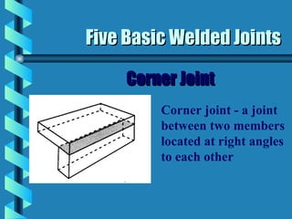
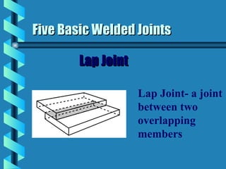
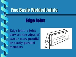
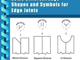
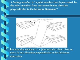
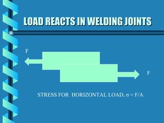
Weld Joint Geometry and
      Welding Symbols
ADVANTAGES & DISADVANTAGES
OF WELDING JOINTS
ADVANTAGES                                 DISADVANTAGES


• Welded joints have low initial cost      • Welded joint cannot be used for
• The process is noiseless.                impact load and vibrations
• welded joints are greater in strength    • Being permanent joint the welded
• Less machining is required after         joint cannot be assembled and
welding.                                   reassembled like screwed joints
• Easy to inspect i.e. by x-rays without
destroying the piece.
• Welded joint can easily be repaired.
GENERAL WELDING SYMBOL
Five Basic Welded Joints

             Butt Joint
Butt joint- a joint
between two
members aligned
approximately in
the same plane
Different Edge Shapes
and Symbols for some
Butt-Joints
Five Basic Welded Joints

    Corner Joint
         Corner joint - a joint
         between two members
         located at right angles
         to each other
Some Different Edge
Shapes and Symbols for
Corner Joints
Five Basic Welded Joints

               T-Joint
T- joint - a joint between
two members located
approximately at right
angles to each other in
the form of a T
Some Different Edge
Shapes and Symbols for T-
Joint
Five Basic Welded Joints

        Lap Joint

                    Lap Joint- a joint
                    between two
                    overlapping
                    members
Some Different Edge
Shapes and Symbols for
Lap Joints
Five Basic Welded Joints

          Edge Joint

Edge joint- a joint
between the edges of
two or more parallel
or nearly parallel
members
Some Different Edge
Shapes and Symbols for
Edge Joints
Proper terminology is needed in
everyday job communication
a Joint design identifies, “the shape ,
  dimensions, and configuration of the joint
a The individual workpieces of a joint are
  called members .
a Three types members nonbutting member,
  butting member , and splice member
A butting member is “a joint member that is prevented, by
the other member from movement in one direction
perpendicular to its thickness dimension”


A nonbutting member is “a joint member that is free to
move in any direction perpendicular to its thickness
dimension
A splice member is “ the work piece that
spans the joint in a spliced joint


                              Single-spliced
                                  butt joint


                             Double-spliced
                              butt joint with
                                joint filler
LOAD REACTS IN WELDING JOINTS

F


                                          F


    STRESS FOR HORIZONTAL LOAD, σ = F/A
ACTIVITY 1

Welding design

  • 1.
    Weld Joint Geometryand Welding Symbols
  • 2.
    ADVANTAGES & DISADVANTAGES OFWELDING JOINTS ADVANTAGES DISADVANTAGES • Welded joints have low initial cost • Welded joint cannot be used for • The process is noiseless. impact load and vibrations • welded joints are greater in strength • Being permanent joint the welded • Less machining is required after joint cannot be assembled and welding. reassembled like screwed joints • Easy to inspect i.e. by x-rays without destroying the piece. • Welded joint can easily be repaired.
  • 3.
  • 4.
    Five Basic WeldedJoints Butt Joint Butt joint- a joint between two members aligned approximately in the same plane
  • 5.
    Different Edge Shapes andSymbols for some Butt-Joints
  • 6.
    Five Basic WeldedJoints Corner Joint Corner joint - a joint between two members located at right angles to each other
  • 7.
    Some Different Edge Shapesand Symbols for Corner Joints
  • 8.
    Five Basic WeldedJoints T-Joint T- joint - a joint between two members located approximately at right angles to each other in the form of a T
  • 9.
    Some Different Edge Shapesand Symbols for T- Joint
  • 10.
    Five Basic WeldedJoints Lap Joint Lap Joint- a joint between two overlapping members
  • 11.
    Some Different Edge Shapesand Symbols for Lap Joints
  • 12.
    Five Basic WeldedJoints Edge Joint Edge joint- a joint between the edges of two or more parallel or nearly parallel members
  • 13.
    Some Different Edge Shapesand Symbols for Edge Joints
  • 14.
    Proper terminology isneeded in everyday job communication a Joint design identifies, “the shape , dimensions, and configuration of the joint a The individual workpieces of a joint are called members . a Three types members nonbutting member, butting member , and splice member
  • 15.
    A butting memberis “a joint member that is prevented, by the other member from movement in one direction perpendicular to its thickness dimension” A nonbutting member is “a joint member that is free to move in any direction perpendicular to its thickness dimension
  • 16.
    A splice memberis “ the work piece that spans the joint in a spliced joint Single-spliced butt joint Double-spliced butt joint with joint filler
  • 17.
    LOAD REACTS INWELDING JOINTS F F STRESS FOR HORIZONTAL LOAD, σ = F/A
  • 18.

Editor's Notes

  • #2 Submitted by Craig Herald Welding Instructor Lee County Area Technology Center Graphics provided compliments of the American Welding Society Education Department