Projection of planes
•Download as PPT, PDF•
40 likes•31,742 views

The document provides instructions for projecting plane figures by describing their position relative to the horizontal and vertical planes. It explains that problems will give the plane figure and its inclination to the planes. The document outlines the 3 step process: 1) assume initial position, 2) consider surface inclination, 3) consider side/edge inclination. Examples are given of different inclinations and the steps are applied to sample problems.

Recommended
More Related Content
What's hot
What's hot (20)
Similar to Projection of planes
Similar to Projection of planes (20)
More from Vaibhav Bajaj
More from Vaibhav Bajaj (20)
Recently uploaded
Recently uploaded (20)
Projection of planes
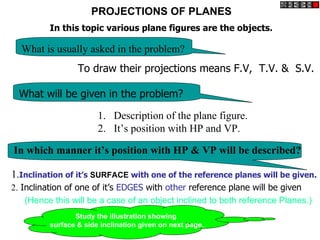
- 1. PROJECTIONS OF PLANES In this topic various plane figures are the objects. What is usually asked in the problem? To draw their projections means F.V, T.V. & S.V. What will be given in the problem? 1. Description of the plane figure. 2. It’s position with HP and VP. In which manner it’s position with HP & VP will be described? 1.Inclination of it’s SURFACE with one of the reference planes will be given. 2. Inclination of one of it’s EDGES with other reference plane will be given (Hence this will be a case of an object inclined to both reference Planes.) Study the illustration showing surface & side inclination given on next page.
- 2. CASE OF A RECTANGLE – OBSERVE AND NOTE ALL STEPS. SURFACE PARALLEL TO HP SURFACE INCLINED TO HP ONE SMALL SIDE INCLINED TO VP PICTORIAL PRESENTATION PICTORIAL PRESENTATION PICTORIAL PRESENTATION For T.V. For Tv For T.V. For Fo For Fv r F.V F.V . . ORTHOGRAPHIC ORTHOGRAPHIC ORTHOGRAPHIC TV-True Shape FV- Inclined to XY FV- Apparent Shape FV- Line // to xy TV- Reduced Shape TV-Previous Shape d’ VP VP VP c’ d1’ c1’ a’ d’ a1’ b1’ b’ c’ a’ ’ b d1 a d a1 d1 c1 b c b1 c1 a1 HP A HP B HP C b1
- 3. PROCEDURE OF SOLVING THE PROBLEM: IN THREE STEPS EACH PROBLEM CAN BE SOLVED:( As Shown In Previous Illustration ) STEP 1. Assume suitable conditions & draw Fv & Tv of initial position. STEP 2. Now consider surface inclination & draw 2nd Fv & Tv. STEP 3. After this,consider side/edge inclination and draw 3rd ( final) Fv & Tv. ASSUMPTIONS FOR INITIAL POSITION: (Initial Position means assuming surface // to HP or VP) 1.If in problem surface is inclined to HP – assume it // HP Or If surface is inclined to VP – assume it // to VP 2. Now if surface is assumed // to HP- It’s TV will show True Shape. And If surface is assumed // to VP – It’s FV will show True Shape. 3. Hence begin with drawing TV or FV as True Shape. 4. While drawing this True Shape – keep one side/edge ( which is making inclination) perpendicular to xy line ( similar to pair no. A on previous page illustration ). Now Complete STEP 2. By making surface inclined to the resp plane & project it’s other view. (Ref. 2nd pair B on previous page illustration ) Now Complete STEP 3. By making side inclined to the resp plane & project it’s other view. (Ref. 3nd pair C on previous page illustration ) APPLY SAME STEPS TO SOLVE NEXT ELEVEN PROBLEMS
- 4. Surface of the plane inclined to………at……… Edge or side or dia. or diagonal of the plane inclined to …….at……… Assumptions for initial position 1. Keep the plane parallel to the principal plane from which it is to be inclined. 2. Keep the edge perpendicular to the principal plane from which it is to be inclined. Steps for solution 1. Incline the plane. 2. Incline the edge.
- 5. PROBLEMS ON PROJECTION OF PLANES (1)Surface inclined to the HP and edge inclined to the VP. 12.7, 3, 2, 12.6, 4, 12, (2) Surface inclined to the VP and edge inclined to the HP. 12.9, 7. (3) Inclination of the surface with the VP given indirectly and that of the edge with the HP given directly 12.10, 12.11, 9 (4) Inclination of the surface with the HP given indirectly and that of the edge with the VP given directly. 10, 8. (5) Surface perpendicular to Profile Plane, inclined to both the HP and the VP 12.14, 6. (6)Edge of a plane inclined to both the HP and the VP. 12.8
- 6. Q12.4: A regular pentagon of 25mm side has one side on the ground. Its plane is inclined at 45º to the HP and perpendicular to the VP. Draw its projections and show its traces Hint: As the plane is inclined to HP, it should be kept parallel to HP with one edge perpendicular to VP c’ d’ ’ b a’ b’ e’ d’ c’ e’ ’ a 45º X Y b b1 a a1 c c1 25 e e1 d d1
- 7. Q.12.5:Draw the projections of a circle of 5 cm diameter having its plane vertical and inclined at 30º to the V.P. Its centre is 3cm above the H.P. and 2cm in front of the V.P. Show also its traces 50 Ø 4’ 41 ’ 3’ 5’ 31 ’ 51’ 2’ 6’ 61 ’ 21’ 1’ 7’ 11’ 71’ 12’ 8’ 121’ 81’ 30 91’ 11’ 9’ 111’ X 10’ Y 101’ 1 20 2, 12 3, 30º 11 4, 1 2, 3, 4, 5, 6, 7 8 10 5, 12 11 10 9 9 6, 8 7
- 8. Problem 5 : draw a regular hexagon of 40 mm sides, with its two sides vertical. Draw a circle of 40 mm diameter in its centre. The figure represents a hexagonal plate with a hole in it and having its surface parallel to the VP. Draw its projections when the surface is vertical and inclined at 30º to the VP. a a’ a1’ 11’ 1’ f1’ 121’ 21’ b1’ f’ 12’ 2’ b’ 11’ 3’ 111’ 31’ 10’ 4’ 101’ 41’ 5’ 91’ 51’ 9’ e1’ c1’ e’ 8’ 6’ c’ 81’ 61’ 7’ 71’ d’ 30º d1’ X Y e f a d b c 10 e f 9 a d 11 8 10 9 8 1 2 3 4 12 1 11 12 7 6 5 7 2 6 3 4 b c 5
- 9. Problem 1 : Draw an equilateral triangle of 75 mm sides and inscribe a circle in it. Draw the projections of the figure, when its plane is vertical and inclined at 30º to the VP and one of the sides of the triangle is inclined at 45º to the HP. a1’ a’ 11’ 1’ 121’ 21’ 12’ 2’ c1’ 11’ 3’ c’ 111’ 31’ 10’ 4’ 101’ 41’ 9’ 5’ 91’ 51’ 8’ 6’ 81’ 61’ 75 7’ 71’ b’ 30º b1’ 45º X Y a a b c 10 b 9 10 9 8 1 2 3 4 11 8 6 5 12 1 11 12 7 7 2 6 3 4 c 5
- 10. Q12.7: Draw the projections of a regular hexagon of 25mm sides, having one of its side in the H.P. and inclined at 60 to the V.P. and its surface making an angle of 45º with the H.P. Read problem and answer following questions 1. Surface inclined to which plane?______ 2. Assumption for initial position? plane // to ____ 3. So which view will show True shape? _______ 4. Which side will be vertical? ___________ Hence begin with __,draw hexagon ______ X-Y line, taking one side vertical. Plane inclined to HP Side on the H.P. making 60° at 45°and ┴ to VP with the VP. e’ e1 ’ d1’ Plane parallel to HP d’ f’ f1’ c’ c1’ a’ b’ c’ f’ d’ e’ ’ b 45º a1’ X a’ Y 60º b1 ’ f f f1 1 a e a1 e1 e1 a1 d b1 d1 d1 b c1 b1 c
- 11. Problem 3: Draw the projections of a regular pentagon of 40 mm side, having its surface inclined at 30º to the H.P. and a side parallel to the H.P. and inclined at an angle of 60º to the V.P. Read problem and answer following questions 1. Surface inclined to which plane?______ 2. Assumption for initial position? plane // to ____ 3. So which view will show True shape? _______ 4. Which side will be vertical? ___________ Hence begin with __,draw hexagon ______ X-Y line, taking one side vertical. Plane inclined to HP Side // to the H.P. making at 30°and ┴ to VP 60° with the VP. d’ d1 ’ Plane parallel to HP e’ ’ c e1 ’ c1’ a’ e’ a’ b’ c’ d’ b’ 30º a1 ’ b1 ’ X Y 60º e1 e1 e a1 d1 a a1 d1 d b c1 b1 b1 c c1
- 12. Q12.6: A square ABCD of 50 mm side has its corner A in the H.P., its diagonal AC inclined at 30º to the H.P. and the diagonal BD inclined at 45º to the V.P. and parallel to the H.P. Draw its projections. Keep AC parallel to the H.P. Incline AC at 30º to the H.P. & BD perpendicular to V.P. i.e. incline the edge view Incline BD at 45º to the V.P. (considering inclination of (FV) at 30º to the HP AC as inclination of the plane) c’ c1’ b’ d’ b1 ’ d1’ b’ a’ d’ c’ a’ 30º X Y 45º 45º a1’ b1 b b1 c1 a c a1 c1 a1 d1 50 d d1
- 13. Q10: Draw a rhombus of 100 mm and 60 mm long diagonals with longer diagonal horizontal. The figure is the top view of a square having 100 mm long diagonals. Draw its front view. c’ c1 b’d’ d1 b1 a’ b’ d’ c’ a’ X Y 60 a1 b b1 a1 d1 b1 60 a c a1 c1 100 c1 d d1 100 100
- 14. Q4: Draw projections of a rhombus having diagonals 125 mm and 50 mm long, the smaller diagonal of which is parallel to both the principal planes, while the other is inclined at 30º to the H.P. Keep AC parallel to the H.P. & Incline AC at 30º to the H.P. Make BD parallel to XY BD perpendicular to V.P. (considering inclination of AC as inclination of the plane and inclination of BD as inclination c’ of edge) c1’ b’ d’ d1 ’ b1 ’ b’ d’ c’ a’ a’ 30º X Y a1 ’ 125 b b1 b1 c1 a1 50 a c c1 a1 d d1 d1
- 15. Q 2:A regular hexagon of 40mm side has a corner in the HP. Its surface inclined at45° to the HP and the top view of the diagonal through the corner which is in the HP makes an angle of 60° with the VP. Draw its projections. Top view of the diagonal Plane inclined to HP making 60° with the VP. Plane parallel to HP at 45°and ┴ to VP d’ d1’ c’ ’ c 1’ e e1’ b’ b1’ f’ f 1’ b’ c’ Y a’ a’ f’ e’ d’ 45° a1’ X 60° 60° f1 f1 e1 a1 f e e1 b1 a d d1 a1 d1 c1 b c b1 c1
- 16. Q7:A semicircular plate of 80mm diameter has its straight edge in the VP and inclined at 45 to HP.The surface of the plate makes an angle of 30 with the VP. Draw its projections. Read problem and answer following questions 1. Surface inclined to which plane?______ 2. Assumption for initial position? plane // to ____ 3. So which view will show True shape? _______ 4. Which side will be vertical? ___________ Hence begin with __,draw hexagon ______ X-Y line, taking one side vertical. Plane in the V.P. with Plane inclined at 30º to the St. edge in V.P. and straight edge ┴ to H.P V.P. and straight edge in the inclined at 45º to the H.P. V.P. 11 11 ’ ’ 1’ 2’ 21 ’ 21 ’ 3’ 31’ 31 ’ 4’ Ø 80 41 ’ 71 ’ 41 ’ 5’ 51’ 51 61 ’ ’ 6’ 71 ’ 61 ’ 7’ 45º 71 11 X 1 30º Y 1 2 3 4 7 7 5 2 21 6 6 61 3 31 5 51 41 4
- 17. Problem 12.9: Read problem and answer following questions A 300 – 600 set square of longest side 1 .Surface inclined to which plane? ------- VP 100 mm long, is in VP and 300 inclined 2. Assumption for initial position? ------// to VP to HP while it’s surface is 450 inclined 3. So which view will show True shape? --- FV to VP.Draw it’s projections 4. Which side will be vertical? ------longest side. (Surface & Side inclinations directly given) Hence begin with FV, draw triangle above X-Y keeping longest side vertical. a’ a1’ 60º c’ side inclined to Hp c1 ’ c1’ a1’ 30º b 1’ b’ b 1’ 300 X ab 450 a1 b1 Y a c b c c1 Surface // to VP Surface inclined to Vp
- 18. Problem 12.8 : Draw the projections of a circle of 50 mm diameter resting on the HP on point A on the circumference. Its plane inclined at 45º to the HP and (a) The top view of the diameter AB making 30º angle with the VP (b) The diameter AB making 30º angle with the VP The difference in these two problems is in step 3 only. In problem no12.8(a) inclination of TV of that AB is given, It could be drawn directly as shown in 3rd step. While in 12.8(b) angle of AB itself i.e. it’s TL, is given. Hence here angle of TL(ab2) is taken, locus of b2 is drawn and then LTV I.e. a1 b1 is marked and final TV was completed.Study illustration carefully. 7’ 6’ b’ b1’71’ 7 2’ 5’ 8’ 8 1’ 8 2’ 6 2’ 6 1’ 9’ 9 1’ 9 2’ 4’ 5 1’ 5 2’ 10’ 101’ 102’ 3’ 4 2’ 4 1’ 2’ 11’ 111’ 112’ 12’ 3 1’ 3 2’ 1’ 45º 121’ X 122’ 1’ 2’ 3’ 6’ 7’ a’ a1’11’ 1 2’ 1 2’ 2 2’ Y 4’ 5’ a’ 12’ 11’ 10’ 9’ 8’ b’ 4 41 31 3 5 31 51 41 21 21 31 2 6 51 41 21 61 a111 11 a1 Ø β 30º 51 61 121 1a 7b 11 a1 b 17 1 121 61 b 17 1 12 8 121 81 111 b2 111 81 b1 71 11 9 111 91 101 91 101 101 91 81 10
- 19. Q12.10: A thin rectangular plate of sides 60 mm X 30 mm has its shorter side in the V.P. and inclined at 30º to the H.P. Project its top view if its front view is a square of 30 mm long sides A rectangle can be seen as a F.V. (square) is drawn first Incline a1’b1’ at 30º to the H.P. square in the F.V. only when its surface is inclined to VP. So for the first view keep the plane // to VP & shorter edge ┴ to HP c1 ’ 60 b’ c’ b1’ c1’ d1’ b1’ 30 a1’ a’ d’ a1 ’ d1 ’ b1 a1 30º X Y c a a d b b 60 c c1 d1 d
- 20. Q12.11: A circular plate of negligible thickness and 50 mm diameter appears as an ellipse in the front view, having its major axis 50 mm long and minor axis 30 mm long. Draw its top view when the major axis of the ellipse is horizontal. A circle can be seen as a ellipse in the F.V. only when its Incline the T.V. till the Incline the F.V. till the surface is inclined to VP. So distance between the end major axis becomes for the first view keep the plane projectors is 30 mm horizontal // to VP. 50 Ø 4’ 41 ’ 41 ’ 3’ 5’ 31’ 51 ’ 51’ 31’ 2’ 6’ 21 ’ 61’ 21 ’ 61 ’ 11’ 71 ’ 1’ 7’ 71’ 11’ 12’ 8’ 121’ 81 ’ 121’ 81 ’ 111’ 91 ’ 11’ 9’ 111’ 101’ Y 91’ X 10’ 11 ’ 101’ 121’ 21 ’ 30 1 2, 31’ 12 111’ 3, 11 1 2, 3, 4, 5, 6, 7 101’ 41 ’ 12 11 10 9 8 4, 10 91 ’ 51’ 5, 9 81’ 61 ’ 6, 8 7
- 21. Problem 9 : A plate having shape of an isosceles triangle has base 50 mm long and altitude 70 mm. It is so placed that in the front view it is seen as an equilateral triangle of 50 mm sides and one side inclined at 45º to xy. Draw its top view An isosceles triangle can be seen as a equilateral triangle in Step 2:F.V. (equilateral Step 3: Incline a1’b1’ at 45º to the F.V. only when its surface triangle) is drawn first the H.P. is inclined to VP. So for the first view keep the plane // to VP, with 50 mm long edge perpendicular to the HP. c1’ a’ a1’ a1’ c’ c1’ 50 b’ b1’ b1’ 45º 70 a1 b1 a.b c a.b c c1
- 22. Problem 1: Read problem and answer following questions Rectangle 30mm and 50mm 1. Surface inclined to which plane? _________ sides is resting on HP on one 2. Assumption for initial position? __________ small side which is 300 inclined 3. So which view will show True shape? ______ to VP,while the surface of the 4. Which side will be vertical? ______________. plane makes 450 inclination with Hence begin with __, draw rectangle _____ XY HP. Draw it’s projections. drawing one small side vertical. Surface // to Hp Surface inclined to Hp d’c’ c’1 d’1 c’d’ a’b’ a’ b’ 450 b’1 a’1 Y X 300 a a1 d1 a1 d Side Inclined to Vp b1 b c b1 c1 d1 12.7,12.9,3,2,7,12,12.6,12.4 c1
- 23. 12.14: A thin circular plate of 70 mm diameter is resting on its circumference such that its plane is inclined at 60º to the H.P. and 30º to the V.P. Draw the projections of the plate. X1 4’ 3’ 5’ 4” 41 ’ 4” 2’ 31’ 51 ’ 6’ 5”3” 5”3” 6”2” 21 ’ 61 ’ 6”2” 1’ 7’ 7”1” 11 ’ 71’ 7”1” 12’ 121’ 8’ 81 ’ 8”12” 8”12” 11’ 41 9’ 60º 9”11” 111’ 91 ’ 51 9”11” 31 101’ 10’ 10” Y X 21 61 11 71 121 81 111 91 101 Y1
- 24. Q. 8: The top view of a plate, the surface of which is inclined at 60º to the HP is a circle of 60 mm diameter. Draw its three views. X1 7’ 7” 6’ 8’ 6” 8” 5’ 9’ 5” 9” 4’ 10’ 4” 10” 3’ 11’ 3” 11” 2’ 12’ 600 2” 12” X 1’ Y 1” 4 3 5 2 6 1 7 12 8 11 9 10 60 Y1
- 25. Problem 3: Read problem and answer following questions A 30 – 60 set square of longest side 0 0 1 .Surface inclined to which plane? ------- VP 100 mm long is in VP and it’s surface 2. Assumption for initial position? ------// to VP 450 inclined to VP. One end of longest 3. So which view will show True shape? --- FV side is 10 mm and other end is 35 mm above HP. Draw it’s projections 4. Which side will be vertical? ------longest side. (Surface inclination directly given. Hence begin with FV, draw triangle above X-Y Side inclination indirectly given) keeping longest side vertical. First TWO steps are similar to previous problem. a1’ Note the manner in which side inclination is given. a’ End A 35 mm above HP & End B is 10 mm above 60º HP. c’ c1 ’ So redraw 2nd FV as final FV placing these ends as said. c1 ’ a1’ 30º b 1’ 35 b 1’ b’ Y 10 X ab 450 a1 b1 a c b c c1 Surface // to VP Surface inclined to Vp
- 26. Problem 4: Read problem and answer following questions A regular pentagon of 30 mm sides is 1. Surface inclined to which plane? ------- HP resting on HP on one of it’s sides with it’s 2. Assumption for initial position? ------ // to HP surface 450 inclined to HP. 3. So which view will show True shape? --- TV Draw it’s projections when the side in HP 4. Which side will be vertical? -------- any side. makes 300 angle with VP Hence begin with TV,draw pentagon below SURFACE AND SIDE INCLINATIONS X-Y line, taking one side vertical. ARE DIRECTLY GIVEN. d’ c’1 d’1 c’e’ e’1 b’ a’ c’e’ d’ b’a’ 45º X Y 300 b’1 a’1 e e1 b1 a a1 c1 a1 d d1 b b1 d1 e1 c c1
- 27. Problem 5: Read problem and answer following questions A regular pentagon of 30 mm sides is resting 1. Surface inclined to which plane? ------- HP on HP on one of it’s sides while it’s opposite 2. Assumption for initial position? ------ // to HP vertex (corner) is 30 mm above HP. 3. So which view will show True shape? --- TV Draw projections when side in HP is 300 4. Which side will be vertical? --------any side. inclined to VP. Hence begin with TV,draw pentagon below SURFACE INCLINATION INDIRECTLY GIVEN X-Y line, taking one side vertical. SIDE INCLINATION DIRECTLY GIVEN: ONLY CHANGE is the manner in which surface inclination is described: One side on Hp & it’s opposite corner 30 mm above Hp. d’ d’1 Hence redraw 1st Fv as a 2nd Fv making above arrangement. Keep a’b’ on xy & d’ 30 mm above xy. c’e’ e’1 30 c’1 b’ a’ c’e’ d’ X Y b’ a’ 300 b’1 a’1 e e1 b1 a a1 c1 a1 d d1 b b1 d1 e1 c c1
- 28. Problem 6: A rhombus of diagonals 40 mm c’ c’1 and 70 mm long respectively has one end of it’s longer diagonal in HP while that d’ b’1 b’ d’1 diagonal is 350 inclined to HP. If the top- b’d’ c’ view of the same diagonal makes 400 X a’ 450 a’1 Y inclination with VP, draw it’s projections. a’ a1 30º d1 d d1 a c a c1 Read problem and answer following questions b1 c1 1. Surface inclined to which plane? ------- HP b 1 b1 2. Assumption for initial position? ------ // to HP 3. So which view will show True shape? --- TV The difference in these two problems is in step 3 only. In problem no.6 inclination of Tv of that diagonal is 4. Which diagonal horizontal? ---------- Longer given,It could be drawn directly as shown in 3rd step. Hence begin with TV,draw rhombus below While in no.7 angle of diagonal itself I.e. it’s TL, is X-Y line, taking longer diagonal // to X-Y given. Hence here angle of TL is taken,locus of c1 Is drawn and then LTV I.e. a1 c1 is marked and final TV was completed.Study illustration carefully. Problem 7: A rhombus of diagonals 40 mm and 70 mm long respectively having c’ c’1 one end of it’s longer diagonal in HP while d’ b’1 that diagonal is 350 inclined to HP and b’ d’1 makes 400 inclination with VP. Draw it’s b’d’ X a’ c’ a’ 450 a’1 Y projections. a1 30 0 d d1 d1 Note the difference in a c a c1 TL construction of 3rd step b1 c 2 b 1 b1 c1 in both solutions.
- 29. c’ c’1 d’ b’1 Problem 8: A circle of 50 mm diameter is a’ b’ d’ c’ b’ resting on Hp on end A of it’s diameter AC a’ 300 a’1 d’1 Y X which is 300 inclined to Hp while it’s Tv d1 450 d is 450 inclined to Vp.Draw it’s projections. a ca c1 1 Read problem and answer following questions 1. Surface inclined to which plane? ------- HP b b1 2. Assumption for initial position? ------ // to HP 3. So which view will show True shape? --- TV The difference in these two problems is in step 3 only. 4. Which diameter horizontal? ---------- AC In problem no.8 inclination of Tv of that AC is Hence begin with TV,draw rhombus below given,It could be drawn directly as shown in 3rd step. X-Y line, taking longer diagonal // to X-Y While in no.9 angle of AC itself i.e. it’s TL, is given. Hence here angle of TL is taken,locus of c1 Is drawn and then LTV I.e. a1 c1 is marked and Problem 9: A circle of 50 mm diameter is final TV was completed.Study illustration carefully. resting on Hp on end A of it’s diameter AC which is 300 inclined to Hp while it makes c’ c’1 ’ b’1 450 inclined to Vp. Draw it’s projections. a’ b’ d’ c’ b ’d a’ a’1 d’1 d d1 d a 300 1 1 Note the difference in TL a ca c1 construction of 3rd step 1 c b in both solutions. 1 1 b b1
- 30. Read problem and answer following questions Problem 10: End A of diameter AB of a circle is in HP 1. Surface inclined to which plane? ------- HP A nd end B is in VP.Diameter AB, 50 mm long is 2. Assumption for initial position? ------ // to HP 300 & 600 inclined to HP & VP respectively. 3. So which view will show True shape? --- TV Draw projections of circle. 4. Which diameter horizontal? ---------- AB Hence begin with TV,draw CIRCLE below X-Y line, taking DIA. AB // to X-Y The problem is similar to previous problem of circle – no.9. But in the 3rd step there is one more change. Like 9th problem True Length inclination of dia.AB is definitely expected but if you carefully note - the the SUM of it’s inclinations with HP & VP is 900. Means Line AB lies in a Profile Plane. Hence it’s both Tv & Fv must arrive on one single projector. So do the construction accordingly AND note the case carefully.. 300 X Y 600 SOLVE SEPARATELY ON DRAWING SHEET TL GIVING NAMES TO VARIOUS POINTS AS USUAL, AS THE CASE IS IMPORTANT
- 31. Problem 11: Read problem and answer following questions A hexagonal lamina has its one side in HP and 1. Surface inclined to which plane? ------- HP Its apposite parallel side is 25mm above Hp and 2. Assumption for initial position? ------ // to HP In Vp. Draw it’s projections. Take side of hexagon 30 mm long. 3. So which view will show True shape? --- TV 4. Which diameter horizontal? ---------- AC ONLY CHANGE is the manner in which surface inclination Hence begin with TV,draw rhombus below is described: X-Y line, taking longer diagonal // to X-Y One side on Hp & it’s opposite side 25 mm above Hp. Hence redraw 1st Fv as a 2nd Fv making above arrangement. Keep a’b’ on xy & d’e’ 25 mm above xy. e’ e’1 d’1 d’ f’ 25 c’ f’1 c1’ X a’ b’ c’ f’ d’e’ b’ a’1 b’1 Y a’ e1 d1 f f1 f1 c1 a e a1 e1 a1 b1 As 3rd step b d b1 d1 redraw 2nd Tv keeping c1 side DE on xy line. c Because it is in VP as said in problem.
- 32. FREELY SUSPENDED CASES. IMPORTANT POINTS 1.In this case the plane of the figure always remains perpendicular to Hp. Problem 12: 2.It may remain parallel or inclined to Vp. An isosceles triangle of 40 mm long 3.Hence TV in this case will be always a LINE view. base side, 60 mm long altitude Is 4.Assuming surface // to Vp, draw true shape in suspended position as FV. freely suspended from one corner of (Here keep line joining point of contact & centroid of fig. vertical ) Base side.It’s plane is 450 inclined to 5.Always begin with FV as a True Shape but in a suspended position. Vp. Draw it’s projections. AS shown in 1st FV. a’1 a’ C b’1 b’ g’ g’1 H G c’ c’1 H/3 X Y A B b a, b a,g c g 450 First draw a given triangle With given dimensions, Locate it’s centroid position c And Similarly solve next problem join it with point of suspension. of Semi-circle
- 33. IMPORTANT POINTS Problem 13 1.In this case the plane of the figure always remains perpendicular to Hp. :A semicircle of 100 mm diameter 2.It may remain parallel or inclined to Vp. is suspended from a point on its 3.Hence TV in this case will be always a LINE view. straight edge 30 mm from the midpoint 4.Assuming surface // to Vp, draw true shape in suspended position as FV. of that edge so that the surface makes (Here keep line joining point of contact & centroid of fig. vertical ) an angle of 450 with VP. 5.Always begin with FV as a True Shape but in a suspended position. Draw its projections. AS shown in 1st FV. A a’ 20 mm p’ P G b’ CG g’ c’ e’ d’ X Y 0.414R b c First draw a given semicircle a With given diameter, b c a p,g d e p, Locate it’s centroid position g And d join it with point of suspension. e
- 34. To determine true shape of plane figure when it’s projections are given. BY USING AUXILIARY PLANE METHOD WHAT WILL BE THE PROBLEM? Description of final Fv & Tv will be given. You are supposed to determine true shape of that plane figure. Follow the below given steps: 2. Draw the given Fv & Tv as per the given information in problem. 3. Then among all lines of Fv & Tv select a line showing True Length (T.L.) (It’s other view must be // to xy) • Draw x1-y1 perpendicular to this line showing T.L. • Project view on x1-y1 ( it must be a line view) • Draw x2-y2 // to this line view & project new view on it. It will be the required answer i.e. True Shape. The facts you must know:- If you carefully study and observe the solutions of all previous problems, You will find IF ONE VIEW IS A LINE VIEW & THAT TOO PARALLEL TO XY LINE, THEN AND THEN IT’S OTHER VIEW WILL SHOW TRUE SHAPE: NOW FINAL VIEWS ARE ALWAYS SOME SHAPE, NOT LINE VIEWS: SO APPLYING ABOVE METHOD: Study Next WE FIRST CONVERT ONE VIEW IN INCLINED LINE VIEW .(By using x1y1 aux.plane) Four Cases THEN BY MAKING IT // TO X2-Y2 WE GET TRUE SHAPE.
- 35. Problem 14 Tv is a triangle abc. Ab is 50 mm long, angle cab is 300 and angle cba is 650. a’b’c’ is a Fv. a’ is 25 mm, b’ is 40 mm and c’ is 10 mm above Hp respectively. Draw projections of that figure and find it’s true shape. As per the procedure- 1.First draw Fv & Tv as per the data. 2.In Tv line ab is // to xy hence it’s other view a’b’ is TL. So draw x1y1 perpendicular to it. 3.Project view on x1y1. a) First draw projectors from a’b’ & c’ on x1y1. b) from xy take distances of a,b & c( Tv) mark on these projectors from x1y1. Name points a1b1 & c1. c) This line view is an Aux.Tv. Draw x2y2 // to this line view and project Aux. Fv on it. for that from x1y1 take distances of a’b’ & c’ and mark from x2y= on new projectors. 4.Name points a’1 b’1 & c’1 and join them. This will be the required true shape. Y1 a1b1 Y2 900 b’ b’1 15 TL a’ 15 C1 10 C’ X1 X X2 a’1 Y c c’1 TRUE SHAPE ALWAYS FOR NEW FV TAKE DISTANCES OF PREVIOUS FV 300 650 AND FOR NEW TV, DISTANCES a b OF PREVIOUS TV 50 mm REMEMBER!!
- 36. Problem 15: Fv & Tv of a triangular plate are shown. Determine it’s true shape. USE SAME PROCEDURE STEPS 50 OF PREVIOUS PROBLEM: 25 BUT THERE IS ONE DIFFICULTY: c’ 15 NO LINE IS // TO XY IN ANY VIEW. a’ 1’ MEANS NO TL IS AVAILABLE. 20 IN SUCH CASES DRAW ONE LINE b’ // TO XY IN ANY VIEW & IT’S OTHER 10 X Y VIEW CAN BE CONSIDERED AS TL 15 x1 FOR THE PURPOSE. a c TL HERE a’ 1’ line in Fv is drawn // to xy. 40 90 0 HENCE it’s Tv a-1 becomes TL. 1 c’1 a’1 y2 b THEN FOLLOW SAME STEPS AND DETERMINE TRUE SHAPE. c1 b’1 (STUDY THE ILLUSTRATION) y1 x2 ALWAYS FOR NEW FV TAKE b1 DISTANCES OF PREVIOUS FV AND FOR NEW TV, DISTANCES TRUE d1 OF PREVIOUS TV SHAP E REMEMBER!!
- 37. PROBLEM 16: Fv & Tv both are circles of 50 mm diameter. Determine true shape of an elliptical plate. ADOPT SAME PROCEDURE. a c is considered as line // to xy. Then a’c’ becomes TL for the purpose. Using steps properly true shape can be 50D y1 Easily determined. b’ b1 y2 Study the illustration. TL ac1 1 a’ c’ b’1 c’1 d’ d1 X1 X d Y X2 ALWAYS, FOR NEW FV a’1 TAKE DISTANCES OF d’1 PREVIOUS FV AND a c TRUE SHAPE FOR NEW TV, DISTANCES OF PREVIOUS TV REMEMBER!! 50 D. b
- 38. Problem 17 : Draw a regular pentagon of 30 mm sides with one side 300 inclined to xy. This figure is Tv of some plane whose Fv is A line 450 inclined to xy. TR U E Determine it’s true shape. b1 SH A PE a1 c1 IN THIS CASE ALSO TRUE LENGTH IS NOT AVAILABLE IN ANY VIEW. X1 BUT ACTUALLY WE DONOT REQUIRE TL TO FIND IT’S TRUE SHAPE, AS ONE a’ e1 d1 VIEW (FV) IS ALREADY A LINE VIEW. SO JUST BY DRAWING X1Y1 // TO THIS b’ VIEW WE CAN PROJECT VIEW ON IT e’ AND GET TRUE SHAPE: c’ Y1 d’ STUDY THE ILLUSTRATION.. 450 X 300 Y e d ALWAYS FOR NEW FV a TAKE DISTANCES OF PREVIOUS FV AND FOR NEW TV, DISTANCES OF PREVIOUS TV c REMEMBER!! b