This paper proposes an alternative topology of an inverter to the existing topologies available in the market. A prototype is intended with the purpose of investigates the possibility of designing an inverter using two Boost Converters. This project initialized with a series of simulations using Matlab in order to determine the feasibility of the proposed topology. The next step is the design and development of the proposed prototype where suitable electronics components are chosen based on the simulation result. A PIC microcontroller is used to control the proposed prototype where a control scheme is created based on the programming in the microcontroller. The performance of the proposed prototype has been verified to be optimum by several practical testing using different values of capacitor, inductor and duty cycle. Lastly, data and analysis are presented in a proper mannered way. In the end, this project intends to produce stepped-up square wave output voltage waveform by proper controlling of two Boost Converters.
NON-ISOLATED SOFT SWITCHING DC-DC CONVERTER AND LOAD AT FULL RANGE OF ZVS IAEME Publication
A non isolated soft switching DC–DC converter and load at full range of zero-voltage
switching (ZVS) characteristic is proposed. The proposed converter consists of an auxiliary circuit,
an inductor, two switches, and 2 diodes to achieving high efficiency at full range of load. At low
and heavy loads, ZVS of switching device is achieved by energy storing component. The inductor
energy stored varies with load and hence results in minimizes conduction loss. This leads to
switching of device for full range of load. The proposed DC - DC converter achieves high
efficiency as switching loss is reduced due to soft switching and ZVS operation which severe to
reduce conduction loss. The efficiency is improved about 4% in boost mode (2.5% in buck mode) at
full range of load. To verify the performance of the proposed converter, experimental results
prototype are presented.
This paper introduces the modelling of a novel three phase AC-AC converter with indirect use of a capacitor as DC voltage link. The proposed converter has high efficiency because it uses Space Vector PWM (SVPWM) technique at both rectificier and inverter stages to operate the pulse width modulation in IGBT switches. The novel converter is equipped with a power factor control to shape the rectifier input current waveform to be sinusoidal and to be in phase with the input voltage. To keep the DC voltage stable, the converter utilizes PI controllers. Simulations are conducted for output voltage from 120 to 300 Volts with output frequency ranging from 30 Hz to 60 Hz. The simulation results show that the converter is able to maintain stable the DC voltage and current. Furthermore, the model demonstrates the benefits of proposed converter in terms of acquiring high input power factor and sinusoidal current waveform at the output side of the inverter.
This paper proposes a new voltage frequency converter (VFC) that converts both voltage and frequency to the required level of voltage and frequency in low voltage networks used in various countries. The proposed converter could be used as a universal power supply for sensitive AC loads. The converter is composed of, input voltage and frequency detection circuitry, full bridge boost rectifier and a DC to AC inverter. In addition, to improve the feasibility and performance of the converter, synchronous reference based PI (SRFPI) controller is adopted, where the system behaves similar to a DC-DC converter. The parameter selection of PI controller is done using a recent optimisation technique called Lightning Search Algorithm (LSA). The simulation of VFC is conducted in MATLAB/Simulink environment. The simulation results shows that LSA based PI controller provides better output voltage regulation with respect to the reference value under various load and input conditions.
A new closed loop AC to DC ĈUK converter is presented in this paper. The conventional ĈUK AC to DC converter has no feedback circuit. Thereby, the output voltage of the converter changes while changing the load. The proposed closed loop converter can regulate voltage with the variation of load over a wide range. Moreover, the power factor and Total Harmonic Distortion (THD) of the supply side current found quite satisfactory from this closed loop ĈUK converter. The converter operates in four steps with a different combination of voltage polarities and switching states. The feedback path consists of a voltage control loop and a current control loop. The closed loop ĈUK converter in this study is compared with the open loop version. Additionally, the comparison is made with the conventional converter of the same topology. The effectiveness in terms of power factor and THD of the proposed converter is verified using simulation results.
Analysis of a Quasi Resonant Switch Mode Power Supply for Low Voltage Applica...IDES Editor
QRC provides efficient and regulated switch mode
power supplies for robotic and satellite applications. This paper
addresses the enhanced controller techniques for high
frequency isolation based push-pull Quasi Resonant
Converter. This technique is similar to the conventional PI
controller technique but varies only the enhancement
constants to improve the time domain response of the
converter. The proposed converter is designed for low output
voltage and power rating, characteristically 5V and 5 W, with
the comprehension of current design trends towards enhanced
performance. At the primary stage, to validate the design of
the converter, simulation is performed in PSIM for ±50% load
variations. A prototype model of this converter is developed.
The results obtained from the experimental set-up are
presented and analysed in detail. The results reveal the
superiority of the proposed method.
Fuzzy based control of Transformer less Coupled inductor based DC-DC converterIJERA Editor
Most of the industrial applications use any one of the basic DC-DC converter configurations namely buck,
boost, buck–boost, and Cuk converters. These converters are non-isolating converters. Buck-boost converters
use inductors for storing energy from the source and release the same to load or output. This results in high
stress across magnetic components. This drawback restricts usage of buck-boost converters to low power
applications. Flyback converters popularly have known as buck-boost converters uses transformers for
achieving wide range of step down and step up voltages. Coupled inductor based converters or tapped inductor
based converters are used for achieving wide input – wide output conversion ratios. Coherent transition between
step-down and step-up modes is achieved by a proper control scheme. This paper proposes fuzzy logic based
closed loop control scheme for control of converter switches. Theoretical derivations of control parameters with
their membership values, mamdani based rules for development of fuzzy rules and simulation results of a
coupled inductor based DC-DC converter using MATLAB / SIMULINK are concluded.
Close Loop Control of Induction Motor Using Z-Source InverterIJSRD
In this paper a new closed loop control of induction motor fed by a Z – source inverter based on the vector control or field oriented control strategy is presented. Induction motor is supplied by Z – source inverter, in the Z – source inverter the term Z denotes impedance which means a combination of L & C element which are cross connected. The Z-source inverter consists of a unique impedance network (or circuit) to couple the inverter main circuit to the power supply, hence providing great features that cannot be observed in the conventional voltage-source inverter and current-source inverters in which capacitor and inductor are used, respectively.In the field oriented control method or vector control method speed of the induction motor, torque & 3 phase stator current is given to the field oriented controller and gate pulses for the inverter is generated to obtain the desired operation of the induction motor.
This paper presents the simulation design of dc/dc interleaved boost converter with zero-voltage switching (ZVS). By employin the interleaved structure, the input current stresses to switching devices were reduced and this signified to a switching conduction loss reduction. All the parameters had been calculated theoretically. The proposed converter circuit was simulated by using MATLAB/Simulink and PSpice software programmes. The converter circuit model, with specifications of output power of 200 W, input voltage range from 10~60 V, and operates at 100 kHz switching frequency was simulated to validate the designed parameters. The results showed that the main switches of the model converter circuit achieved ZVS conditions during the interleaving operation. Consequently, the switching losses in the main switching devices were reduced. Thus, the proposed converter circuit model offers advantages of input current stress and switching loss reductions. Hence, based on the designed parameters and results, the converter model can be extended for hardware implementation.
Average current control of DC-DC Cuk Converters as Power Factor CorrectorIJERA Editor
The era of electronic devices in all loads due to the manufacturing technologies replaced many conventional electrical or mechanical loads including lighting loads where Light Emitting Diodes (LEDs) is becoming an emerging technique with many advantages. High frequency switching dc-dc converter is a new technology to control the load and the supply side simultaneously. Due to additional harmonics generated by these switching converters power factor correction has become a necessity in utility side. This paper focuses on the power factor correction of the supply side when employing an ideal LED load with dc-dc Cuk converter. This paper also illustrates the controlling of the power factor correction employing high switching frequency dc-dc converters. The control loops employed are discussed and the strategy for designing the compensator is also explained. The simulated results have been shown to ascertain the accepted performance of the power factor correction converter.
Application of PWM Control Strategy on Z-Source Isolated Dual active bridge D...IJMER
This project presents a Z-source with bidirectional dc–dc converter. The switching count is
reduced by adding a passive element. Thus, we are improving the output voltage level. The voltage
regulation range of proposed converter is better than that of the traditional bidirectional dc–dc
converter. The fully bridge symmetrical circuit configuration, is neither a high-voltage side nor a lowvoltage
side in the circuit structure, and the sources connected to the dc side of each H-bridge circuit
with voltage sources and current sources. This method can reduce current stress and improves the
system efficiency.
In this paper we are presenting a dual active bridge (DAB) dc–dc converter is also known as
Bidirectional DC-DC converter. Both simulation results are shown by using MATLAB software.
DESIGN OF A MULTIFUNCTIONAL FLYBACK DC-DC CONVERTER WITH CURRENT CONTROLIAEME Publication
This paper proposes a set of design techniques to build a DC-DC converter for the interconnection of different sources of renewable energy with storage elements and flexible load profiles. This type of multifunctional DC-DC converter is essential to provide the dispatch of energy generation to storage connected to the DC bus or allow energy exchange with the AC network, with different decision modes as a function of the state of charge of batteries, with the forecast of the consumption of a house with renewable production. This work emphasizes the application of a method to design switched mode flyback converters with current control capabilities on the output side.
Bridgeless CUK Power Factor Corrector with Regulated Output Voltagepaperpublications3
Abstract:A single-phase, bridgeless Cuk AC/DC power factor correction (PFC) rectifier with regulated positive output voltage is proposed in this work. For low output voltage product applications, the rectifier is designed to convert high input voltage to low output voltage. This work presents bridgeless single-phase AC-DC power factor correction (PFC) rectifier based on Cuk topology. The topology does not possess input diode bridge and have only single semiconductor switches in the current owing path during each interval of the switching cycle, which resulting in less conduction losses and better thermal management. This topology is designed to work in discontinuous conduction mode (DCM). The advantages of Cuk converter are also available when bridgeless circuit topology is introduced. The operation is symmetrical in two half-line cycles of input voltage. In conventional, output voltage varies according to input voltage. A closed loop control technique is designed to regulate the output voltage in the desired level. Performance and applicability of this converter is presented on the basis of simulation in MATLAB/SIMULINK.
The projected diode assisted Neutral Point Diode Clamed (NPC-MLI) with the photovoltaic system produces a maximum voltage gain that is comparatively higher than those of other boost conversion techniques. This paper mainly explores vector selection approach pulse-width modulation (PWM) strategies for diode-assisted NPC-MLI to obtain a maximum voltage gain without compromising in waveform quality. To obtain a high voltage gain maximum utilization of dc-link voltage and stress on the power switches must be reduced. From the above issues in the diode assisted NPC-MLI leads to vector selection approach PWM technique to perform capacitive charging in parallel and discharging in series to obtain maximum voltage gain. The operation principle and the relationship of voltage gain versus voltage boost duty ratio and switching device voltage stress versus voltage gain are theoretically investigated in detail. Owing to better performance, diode-assisted NPC-MLI is more promising and competitive topology for wide range dc/ac power conversion in a renewable energy application. Furthermore, theoretically investigated are validated via simulation and experimental results.
Power Quality Improvement Using Cascaded H-Bridge Multilevel Inverter Based D...IJERA Editor
Cascaded multilevel configuration of the inverter has the advantage of its simplicity and modularity over the
configurations of the diode-clamped and flying capacitor multilevel inverters. This paper presents a threephase,
five-level and seven level cascaded multilevel voltage source inverter based active filter for power line
conditioning to improve power quality in the distribution network. The DSTATCOM helps to improve the
power factor and eliminate the Total Harmonics Distortion (THD) drawn from a Non-Liner Diode Rectifier
Load (NLDRL). The compensation process is based on concept of p-q theory. A CHB Inverter is considered for
shunt compensation of a 11 kV distribution system. Finally a level shifted PWM (LSPWM) and phase shifted
PWM (PSPWM) techniques are adopted to investigate the performance of CHB Inverter. The results are
obtained through Matlab/Simulink software package.
International Journal of Engineering Research and Applications (IJERA) is an open access online peer reviewed international journal that publishes research and review articles in the fields of Computer Science, Neural Networks, Electrical Engineering, Software Engineering, Information Technology, Mechanical Engineering, Chemical Engineering, Plastic Engineering, Food Technology, Textile Engineering, Nano Technology & science, Power Electronics, Electronics & Communication Engineering, Computational mathematics, Image processing, Civil Engineering, Structural Engineering, Environmental Engineering, VLSI Testing & Low Power VLSI Design etc.
Analysis and Simulation of Solar PV Connected with Grid Accomplished with Boo...YogeshIJTSRD
This paper deals with a solar PV array connected with grid system. This system consists of PV cells with 30 KW system, Boost converter, three phase inverter with suitable control system and three phase load. This paper gives analysis of each components of the system. The output voltage from the solar PV cells are variable according to radiation intensity and temperature so in order to connect with grid the output voltage should be fixed and converted to AC voltage and this job will be done by an inverter. A very effective control system has been developed for the inverter based on pulse width modulation. This paper presents an intensive performance and dynamic behavior of a grid related PV energy conversion system. The PV system is developed and simulated with the help of MATLAB Simulink software environment. Abhishek Verma | Dr. Anup Mishra | Brahma Nand Thakur "Analysis and Simulation of Solar PV Connected with Grid Accomplished with Boost Converter and PWM Based Inverter" Published in International Journal of Trend in Scientific Research and Development (ijtsrd), ISSN: 2456-6470, Volume-5 | Issue-3 , April 2021, URL: https://www.ijtsrd.com/papers/ijtsrd40056.pdf Paper URL: https://www.ijtsrd.com/engineering/electrical-engineering/40056/analysis-and-simulation-of-solar-pv-connected-with-grid-accomplished-with-boost-converter-and-pwm-based-inverter/abhishek-verma
IEEE 2015-15 Power Electronics and Power System Project titles for ME and BE Students,Bangalore.power electronics and power system projects in bangalore.
Design and Simulation of Power Factor Correction Boost Converter using Hyster...ijtsrd
Nowadays various power converters like AC DC or DC DC are widely used due to their flexible output voltage and high efficiency. But these converters take the current in the form of pulses from the utility grid so that the high Total Harmonic Distortion THD and poor Power Factor PF are the major disadvantages of these converters. Hence there is a continuous need for PF improvement and reduction of line current harmonics. The most popular topology for Active Power Factor Correction APFC is a boost converter as it draws continuous input current. This input current can be manipulated by Hysteresis control technique. The boost converter can perform this type of active power factor correction in many discontinuous and continuous modes. The design and simulation of boost converter with power factor correction in continuous conduction mode is represented by using MATLAB SIMULINK software. Yu Yu Khin | Yan Aung Oo "Design and Simulation of Power Factor Correction Boost Converter using Hysteresis Control" Published in International Journal of Trend in Scientific Research and Development (ijtsrd), ISSN: 2456-6470, Volume-3 | Issue-5 , August 2019, URL: https://www.ijtsrd.com/papers/ijtsrd27905.pdfPaper URL: https://www.ijtsrd.com/engineering/electrical-engineering/27905/design-and-simulation-of-power-factor-correction-boost-converter-using-hysteresis-control/yu-yu-khin
Renewable Energy Based on Current Fed Switched Inverter for Smart Grid Applic...MangaiK4
Abstract - Renewable energy is used in the current fed switched inverter for high power production. High voltage support, wide yield ranges of operation, shoot-through resistance are a portion of the desired properties of an inverter for a reliable, versatile and less ripple AC inversion. This paper proposes a single stage, high boost inverter with buck-boost capacity which has a few particular advantages over traditional voltage source inverters (VSI) like better EMI noise, wide input and output voltage range of operation, and so on. The proposed inverter is named as Current-Fed Switched Inverter (CFSI). A renewable energy based converter structure of CFSI has been created which supplies both AC and DC loads, at the same time, from a single DC supply which makes it reasonable for DC smart grid application. This paper proposes the operation and control of a CFSI based converter which directs the AC and DC conversion voltages at their reference. The advancement of the proposed converter from essential current fed DC/DC topology is explained. The closed loop controller is verified by using the MATLAB/ Simulink environment.
A Integrated Technique of SIDO PFC Fly back Converter in power systemIJMTST Journal
Energy saving is the major international efforts to control down the global warming .Power electronics based devices has being improving day by day for saving the electrical energy in the power grids. The govt. of India is also contributing several projects based on energy conservation. The Designing of a single-inductor dual output (SIDO) fly-back power factor correction (PFC) converter is proposed, in which the PFC and power conversion are done at the same time, multiplexing of a single-inductor is implemented through which each output can be regulated independently. The converter will be operating under in critical conduction mode (CRM). A SIDO PFC converter is a system of dual efficient DC output obtained from the AC source, it can also be replaced by solar panel and our system is capable of running a dc motor also, fly back converter can be used in both ac-dc and dc-dc conversion process. The efficiency along with power factor, total harmonic distortion (THD), settling time and output accuracy of this converter will be improved by implementing the neural network as controllers in the system
This paper presents parameters analysis of 4-level capacitor-clamped boost converter with hard-switching and soft-switching implementation. Principally, by considering the selected circuit structure of the 4-level capacitor-clamped boost converter and appropriate pulse width modulation (PWM) switching strategy, the overall converter volume able to be reduced. Specifically, phase-shifted of 120° of each switching signal is applied in the 4-level capacitor-clamped boost converter in order to increase the inductor current ripple frequency, thus the charging and discharging times of the inductor is reduced. Besides, volume of converters is greatly reduced if very high switching frequency is considered. However, it causes increasing of semiconductor losses and consequently the converter efficiency is affected. The results show that the efficiency of 2-level conventional boost converter and 4-level capacitor-clamped boost converter are 98.59% and 97.67%, respectively in hard-switching technique, and 99.31% and 98.15%, respectively in soft-switching technique. Therefore, by applying soft-switching technique, switching loss of the semiconductor devices is greatly minimized although high switching frequency is applied. In this study, passive lossless snubber circuit is selected for the soft-switching implementation in the 4-level capacitor-clamped boost converter. Based on the simulation results, the switching loss is approximately eliminated by applying soft-switching technique compared to the hard-switching technique implementation.
This paper presents the detail circuitry modeling of single phase off-grid inverter for small standalone system applications. The entire model is developed in MATLAB/Simulink platform using circuitry model. This off grid inverter consists of a high frequency DC-DC step up converter cascaded with a full bridge PI control voltage source inverter using SPWM modulation with LC filter to produce sine wave output. This is a common design used in many small commercial off-grid inverter. This off-grid inverter model is capable to produce AC sinewave output voltage at 230 V 50 Hz up to 1 kW power from a 48 V DC lead acid battery source. The AC sine wave output waveform achieved a voltage Total Harmonic Distortion (THD) of less than 1 % which is almost a pure sine wave. The conversion efficiency performance of the off-grid inverter achieved more than 94 %. The performance of the model is validated by real commercial off-grid inverter. The performance validation experiment shows that the off-grid inverter Simulink model conversion efficiency and THD performance are comparable to the commercial off-grid inverter. This model contributes to assist small to medium standalone system load and battery sizing design with greater accuracy.
This paper deals with implementation of a multi-output Series Resonant Inverter(SRI) for induction heating applications, which uses pulse density modulation(PDM) control for full bridge Series resonant inverters for output voltage and power control. It ensures better efficiency performances than conventional control strategies. The proposed converter can be considered as a two output extension of a full bridge inverter. This full bridge inverter can control the two outputs, simultaneously and independently, up to their rated powers, which reduces the usage of number of components as compared with conventional method. It also ensures higher utilization of switches used for its operation. A two output full bridge series resonant inverter is simulated and implemented. The Experimental results are compared with the simulation results.
Design and Simulation of Efficient DC-DC Converter Topology for a Solar PV Mo...Sajin Ismail
Modulated Integrated Converter systems are considered to be the new and global turning point in the field of
Solar PV systems. These converters are highly recognised for its modular size and compact nature and they are supposed to
be attached directly with each PV module and since one PV module is having the power rating of a few watts ranging from
0-500Ws, the design rating would be in the same range and thus the most vital condition in such a design is efficiency
under these relatively low loads. In this paper an isolated interleaved boost converter topology is considered in the DC-DC
section and which is designed and simulated for a specific power rating (250W) and the efficiency is analysed with varying
load conditions and compared with the target efficiency of the system.
Simulation of D-STATCOM to study Voltage Stability in Distribution systemijsrd.com
This paper presents the simulation of D-statcom to understand the improvement of voltage stability [1] of distribution system. The power circuits of the D-STATCOM and distribution networks are made up of simpower system blocks, while the control circuits made with the simulink blocks The STATCOM is applied to regulate transmission voltage to allow greater power flow in a voltage limited transmission network, in the same manner as a static var compensator (SVC), the STATCOM has further potential by giving an inherently faster response and greater output to a system with depressed voltage and offers improved quality of supply. The main applications of the STATCOM are; Distribution STATCOM (D-STATCOM) exhibits high speed control of reactive power to provide voltage stabilization and other type of system control. The DSTATCOM protects the utility transmission or distribution system from voltage sag and /or flicker caused by rapidly varying reactive current demand. During the transient conditions the D-STATCOM provides leading or lagging reactive power to active system stability, power factor correction and load balancing.
Analysis of a Single Stage Three Level Converter for a Wind Driven Self Excit...idescitation
In this project work, a three phase single stage three level Converter is
implemented for a wind energy conversion system. The proposed system is designed for a
three phase wind driven Self-Excited Induction Generator (SEIG). The SEIG output is
rectified with zero-dead band condition and the output of the converter is continuous. The
three level converter is designed and the performance characteristics are studied. The three
level converter is operated at a switching frequency of 50kHz to obtain a constant three level
output. The proposed model has been simulated in MATALAB Simulink. The hardware
prototype model is developed for a lower power rating and the results are compared.
International Journal of Engineering Research and Applications (IJERA) is an open access online peer reviewed international journal that publishes research and review articles in the fields of Computer Science, Neural Networks, Electrical Engineering, Software Engineering, Information Technology, Mechanical Engineering, Chemical Engineering, Plastic Engineering, Food Technology, Textile Engineering, Nano Technology & science, Power Electronics, Electronics & Communication Engineering, Computational mathematics, Image processing, Civil Engineering, Structural Engineering, Environmental Engineering, VLSI Testing & Low Power VLSI Design etc.
The paper describes the single stage AC-AC converter. This converter is a good alternative to quasi direct back to back converter. This single stage converter is called Matrix Converter. Matrix converter is an array of controlled semiconductor switches that connects three phase source to the three phase load. This converter provides bidirectional power flow, sinusoidal input and output waveforms and they have no dc link storage elements. Simulation model and results presented showing Venturini control method of matrix converter.
A Novel Power Factor Correction Rectifier for Enhancing Power QualityIJPEDS-IAES
In this paper, the disturbances in power system due to low quality of power
are discussed and a current injection method to maintain the sinusoidal input
current which will reduce the total current harmonic distortion (THD) as well
as improve the power factor nearer to unity is proposed. The proposed
method makes use of a novel controlled diode rectifier which involves the
use of bidirectional switches across the front-end rectifier and the operation
of the converter is fully analyzed. The main feature of the topology is low
cost, small size, high efficiency and simplicity, and is excellent for
retrofitting front-end rectifier of existing ac drives, UPS etc. A novel strategy
implementing reference compensation current depending on the load
harmonics and a control algorithm for three-phase three-level unity PF
rectifier which draws high quality sinusoidal supply currents and maintains
good dc link- voltage regulation under wide load variation. The proposed
technique can be applied as a retrofit to a variety of existing thyristor
converters which uses three bidirectional switches operating at low frequency
and a half-bridge inverter operating at high frequency .The total power
delivered to the load is processed by the injection network, the proposed
converter offers high efficiency and not only high power factor but also the
Total Harmonic Distortion is reduced. Theoretical analysis is verified by
digital simulation and a hardware proto type module is implemented in order
to confirm the feasibility of the proposed system. This scheme in general is
suitable for the common variable medium-to high-power level DC load
applications.
The aim of this research is the speed tracking of the permanent magnet synchronous motor (PMSM) using an intelligent Neural-Network based adapative backstepping control. First, the model of PMSM in the Park synchronous frame is derived. Then, the PMSM speed regulation is investigated using the classical method utilizing the field oriented control theory. Thereafter, a robust nonlinear controller employing an adaptive backstepping strategy is investigated in order to achieve a good performance tracking objective under motor parameters changing and external load torque application. In the final step, a neural network estimator is integrated with the adaptive controller to estimate the motor parameters values and the load disturbance value for enhancing the effectiveness of the adaptive backstepping controller. The robsutness of the presented control algorithm is demonstrated using simulation tests. The obtained results clearly demonstrate that the presented NN-adaptive control algorithm can provide good trackingperformances for the speed trackingin the presence of motor parameter variation and load application.
This paper presents a fast and accurate fault detection, classification and direction discrimination algorithm of transmission lines using one-dimensional convolutional neural networks (1D-CNNs) that have ingrained adaptive model to avoid the feature extraction difficulties and fault classification into one learning algorithm. A proposed algorithm is directly usable with raw data and this deletes the need of a discrete feature extraction method resulting in more effective protective system. The proposed approach based on the three-phase voltages and currents signals of one end at the relay location in the transmission line system are taken as input to the proposed 1D-CNN algorithm. A 132kV power transmission line is simulated by Matlab simulink to prepare the training and testing data for the proposed 1D- CNN algorithm. The testing accuracy of the proposed algorithm is compared with other two conventional methods which are neural network and fuzzy neural network. The results of test explain that the new proposed detection system is efficient and fast for classifying and direction discrimination of fault in transmission line with high accuracy as compared with other conventional methods under various conditions of faults.
Among the most widespread renewable energy sources is solar energy; Solar panels offer a green, clean, and environmentally friendly source of energy. In the presence of several advantages of the use of photovoltaic systems, the random operation of the photovoltaic generator presents a great challenge, in the presence of a critical load. Among the most used solutions to overcome this problem is the combination of solar panels with generators or with the public grid or both. In this paper, an energy management strategy is proposed with a safety aspect by using artificial neural networks (ANNs), in order to ensure a continuous supply of electricity to consumers with a maximum solicitation of renewable energy.
In this paper, the artificial neural network (ANN) has been utilized for rotating machinery faults detection and classification. First, experiments were performed to measure the lateral vibration signals of laboratory test rigs for rotor-disk-blade when the blades are defective. A rotor-disk-blade system with 6 regular blades and 5 blades with various defects was constructed. Second, the ANN was applied to classify the different x- and y-axis lateral vibrations due to different blade faults. The results based on training and testing with different data samples of the fault types indicate that the ANN is robust and can effectively identify and distinguish different blade faults caused by lateral vibrations in a rotor. As compared to the literature, the present paper presents a novel work of identifying and classifying various rotating blade faults commonly encountered in rotating machines using ANN. Experimental data of lateral vibrations of the rotor-disk-blade system in both x- and y-directions are used for the training and testing of the network.
This paper focuses on the artificial bee colony (ABC) algorithm, which is a nonlinear optimization problem. is proposed to find the optimal power flow (OPF). To solve this problem, we will apply the ABC algorithm to a power system incorporating wind power. The proposed approach is applied on a standard IEEE-30 system with wind farms located on different buses and with different penetration levels to show the impact of wind farms on the system in order to obtain the optimal settings of control variables of the OPF problem. Based on technical results obtained, the ABC algorithm is shown to achieve a lower cost and losses than the other methods applied, while incorporating wind power into the system, high performance would be gained.
The significance of the solar energy is to intensify the effectiveness of the Solar Panel with the use of a primordial solar tracking system. Here we propounded a solar positioning system with the use of the global positioning system (GPS) , artificial neural network (ANN) and image processing (IP) . The azimuth angle of the sun is evaluated using GPS which provide latitude, date, longitude and time. The image processing used to find sun image through which centroid of sun is calculated and finally by comparing the centroid of sun with GPS quadrate to achieve optimum tracking point. Weather conditions and situation observed through AI decision making with the help of IP algorithms. The presented advance adaptation is analyzed and established via experimental effects which might be made available on the memory of the cloud carrier for systematization. The proposed system improve power gain by 59.21% and 10.32% compare to stable system (SS) and two-axis solar following system (TASF) respectively. The reduced tracking error of IoT based Two-axis solar following system (IoT-TASF) reduces their azimuth angle error by 0.20 degree.
Kosovo has limited renewable energy resources and its power generation sector is based on fossil fuels. Such a situation emphasizes the importance of active research and efficient use of renewable energy potential. According to the analysis of meteorological data for Kosovo, it can be concluded that among the most attractive potential wind power sites are the locations known as Kitka (42° 29' 41" N and 21° 36' 45" E) and Koznica (42° 39′ 32″ N, 21° 22′30″E). The two terrains in which the analysis was carried out are mountain areas, with altitudes of 1142 m (Kitka) and 1230 m (Koznica). the same measuring height, about 84 m above the ground, is obtained for these average wind speeds: Kitka 6,667 m/s and Koznica 6,16 m/s. Since the difference in wind speed is quite large versus a difference in altitude that is not being very large, analyses are made regarding the terrain characteristics including the terrain relief features. In this paper it will be studied how much the roughness of the terrain influences the output energy. Also, that the assumption to be taken the same as to how much they will affect the annual energy produced.
Large-scale grid-tied photovoltaic (PV) station are increasing rapidly. However, this large penetration of PV system creates frequency fluctuation in the grid due to the intermittency of solar irradiance. Therefore, in this paper, a robust droop control mechanism of the battery energy storage system (BESS) is developed in order to damp the frequency fluctuation of the multi-machine grid system due to variable active power injected from the PV panel. The proposed droop control strategy incorporates frequency error signal and dead-band for effective minimization of frequency fluctuation. The BESS system is used to consume/inject an effective amount of active power based upon the frequency oscillation of the grid system. The simulation analysis is carried out using PSCAD/EMTDC software to prove the effectiveness of the proposed droop control-based BESS system. The simulation result implies that the proposed scheme can efficiently curtail the frequency oscillation.
This study investigates experimentally the performance of two-dimensional solar tracking systems with reflector using commercial silicon based photovoltaic module, with open and closed loop control systems. Different reflector materials were also investigated. The experiments were performed at the Hashemite University campus in Zarqa at a latitude of 32⁰, in February and March. Photovoltaic output power and performance were analyzed. It was found that the modified photovoltaic module with mirror reflector generated the highest value of power, while the temperature reached a maximum value of 53 ̊ C. The modified module suggested in this study produced 5% more PV power than the two-dimensional solar tracking systems without reflector and produced 12.5% more PV power than the fixed PV module with 26⁰ tilt angle.
This paper focuses on the modeling and control of a wind energy conversion chain using a permanent magnet synchronous machine. This system behaves a turbine, a generator, DC/DC and DC/AC power converters. These are connected on both sides to the DC bus, where the inverter is followed by a filter which is connected to the grid. In this paper, we have been used two types of controllers. For the stator side converter, we consider the Takagi-Sugeno approach where the parameters of controller have been computed by the theory of linear matrix inequalities. The stability synthesis has been checked using the Lyapunov theory. According to the grid side converter, the proportional integral controller is exploited to keep a constant voltage on the DC bus and control both types of powers. The simulation results demonstrate the robustness of the approach used.
The development of modeling wind speed plays a very important in helping to obtain the actual wind speed data for the benefit of the power plant planning in the future. The wind speed in this paper is obtained from a PCE-FWS 20 type measuring instrument with a duration of 30 minutes which is accumulated into monthly data for one year (2019). Despite the many wind speed modeling that has been done by researchers. Modeling wind speeds proposed in this study were obtained from the modified Rayleigh distribution. In this study, the Rayleigh scale factor (Cr) and modified Rayleigh scale factor (Cm) were calculated. The observed wind speed is compared with the predicted wind characteristics. The data fit test used correlation coefficient (R2), root means square error (RMSE), and mean absolute percentage error (MAPE). The results of the proposed modified Rayleigh model provide very good results for users.
This paper deals with an advanced design for a pump powered by solar energyto supply agricultural lands with water and also the maximum power point is used to extract the maximum value of the energy available inside the solar panels and comparing between techniques MPPT such as Incremental conductance, perturb & observe, fractional short current circuit, and fractional open voltage circuit to find the best technique among these. The solar system is designed with main parts: photovoltaic (PV) panel, direct current/direct current (DC/DC) converter, inverter, filter, and in addition, the battery is used to save energy in the event that there is an increased demand for energy and not to provide solar radiation, as well as saving energy in the case of generation more than demand. This work was done using the matrix laboratory (MATLAB) simulink program.
The objective of this paper is to provide an overview of the current state of renewable energy resources in Bangladesh, as well as to examine various forms of renewable energies in order to gain a comprehensive understanding of how to address Bangladesh's power crisis issues in a sustainable manner. Electricity is currently the most useful kind of energy in Bangladesh. It has a substantial influence on a country's socioeconomic standing and living standards. Maintaining a stable source of energy at a cost that is affordable to everyone has been a constant battle for decades. Bangladesh is blessed with a wealth of natural resources. Bangladesh has a huge opportunity to accelerate its economic development while increasing energy access, livelihoods, and health for millions of people in a sustainable way due to the renewable energy system.
When the irradiance distribution over the photovoltaic panels is uniform, the pursuit of the maximum power point is not reached, which has allowed several researchers to use traditional MPPT techniques to solve this problem Among these techniques a PSO algorithm is used to have the maximum global power point (GMPPT) under partial shading. On the other hand, this one is not reliable vis-à-vis the pursuit of the MPPT. Therefore, in this paper we have treated another technique based on a new modified PSO algorithm so that the power can reach its maximum point. The PSO algorithm is based on the heuristic method which guarantees not only the obtaining of MPPT but also the simplicity of control and less expensive of the system. The results are obtained using MATLAB show that the proposed modified PSO algorithm performs better than conventional PSO and is robust to different partial shading models.
A stable operation of wind turbines connected to the grid is an essential requirement to ensure the reliability and stability of the power system. To achieve such operational objective, installing static synchronous compensator static synchronous compensator (STATCOM) as a main compensation device guarantees the voltage stability enhancement of the wind farm connected to distribution network at different operating scenarios. STATCOM either supplies or absorbs reactive power in order to ensure the voltage profile within the standard-margins and to avoid turbine tripping, accordingly. This paper present new study that investigates the most suitable-location to install STATCOM in a distribution system connected wind farm to maintain the voltage-levels within the stability margins. For a large-scale squirrel cage induction generator squirrel-cage induction generator (SCIG-based) wind turbine system, the impact of STATCOM installation was tested in different places and voltage-levels in the distribution system. The proposed method effectiveness in enhancing the voltage profile and balancing the reactive power is validated, the results were repeated for different scenarios of expected contingencies. The voltage profile, power flow, and reactive power balance of the distribution system are observed using MATLAB/Simulink software.
The electrical and environmental parameters of polymer solar cells (PSC) provide important information on their performance. In the present article we study the influence of temperature on the voltage-current (I-V) characteristic at different temperatures from 10 °C to 90 °C, and important parameters like bandgap energy Eg, and the energy conversion efficiency η. The one-diode electrical model, normally used for semiconductor cells, has been tested and validated for the polemeral junction. The PSC used in our study are formed by the poly(3-hexylthiophene) (P3HT) and [6,6]-phenyl C61-butyric acid methyl ester (PCBM). Our technique is based on the combination of two steps; the first use the Least Mean Squares (LMS) method while the second use the Newton-Raphson algorithm. The found results are compared to other recently published works, they show that the developed approach is very accurate. This precision is proved by the minimal values of statistical errors (RMSE) and the good agreement between both the experimental data and the I-V simulated curves. The obtained results show a clear and a monotonic dependence of the cell efficiency on the studied parameters.
The inverter is the principal part of the photovoltaic (PV) systems that assures the direct current/alternating current (DC/AC) conversion (PV array is connected directly to an inverter that converts the DC energy produced by the PV array into AC energy that is directly connected to the electric utility). In this paper, we present a simple method for detecting faults that occurred during the operation of the inverter. These types of faults or faults affect the efficiency and cost-effectiveness of the photovoltaic system, especially the inverter, which is the main component responsible for the conversion. Hence, we have shown first the faults obtained in the case of the short circuit. Second, the open circuit failure is studied. The results demonstrate the efficacy of the proposed method. Good monitoring and detection of faults in the inverter can increase the system's reliability and decrease the undesirable faults that appeared in the PV system. The system behavior is tested under variable parameters and conditions using MATLAB/Simulink.
The electrical distribution network is undergoing tremendous modifications with the introduction of distributed generation technologies which have led to an increase in fault current levels in the distribution network. Fault current limiters have been developed as a promising technology to limit fault current levels in power systems. Though, quite a number of fault current limiters have been developed; the most common are the superconducting fault current limiters, solid-state fault current limiters, and saturated core fault current limiters. These fault current limiters present potential fault current limiting solutions in power systems. Nevertheless, they encounter various challenges hindering their deployment and commercialization. This research aimed at designing a bridge-type nonsuperconducting fault current limiter with a novel topology for distribution network applications. The proposed bridge-type nonsuperconducting fault current limiter was designed and simulated using PSCAD/EMTDC. Simulation results showed the effectiveness of the proposed design in fault current limiting, voltage sag compensation during fault conditions, and its ability not to affect the load voltage and current during normal conditions as well as in suppressing the source powers during fault conditions. Simulation results also showed very minimal power loss by the fault current limiter during normal conditions.
This paper provides a new approach to reducing high-order harmonics in 400 Hz inverter using a three-level neutral-point clamped (NPC) converter. A voltage control loop using the harmonic compensation combined with NPC clamping diode control technology. The capacitor voltage imbalance also causes harmonics in the output voltage. For 400 Hz inverter, maintain a balanced voltage between the two input (direct current) (DC) capacitors is difficult because the pulse width modulation (PWM) modulation frequency ratio is low compared to the frequency of the output voltage. A method of determining the current flowing into the capacitor to control the voltage on the two balanced capacitors to ensure fast response reversal is also given in this paper. The combination of a high-harmonic resonator controller and a neutral-point voltage controller working together on the 400 Hz NPC inverter structure is given in this paper.
Direct current (DC) electronic load is a useful equipment for testing the electrical system. It can emulate various load at a high rating. The electronic load requires a power converter to operate and a linear regulator is a common option. Nonetheless, it is hard to control due to the temperature variation. This paper proposed a DC electronic load using the boost converter. The proposed electronic load operates in the continuous current mode and control using the integral controller. The electronic load using the boost converter is compared with the electronic load using the linear regulator. The results show that the boost converter able to operate as an electronic load with an error lower than 0.5% and response time lower than 13 ms.
More from International Journal of Power Electronics and Drive Systems (20)
Immunizing Image Classifiers Against Localized Adversary Attacksgerogepatton
This paper addresses the vulnerability of deep learning models, particularly convolutional neural networks
(CNN)s, to adversarial attacks and presents a proactive training technique designed to counter them. We
introduce a novel volumization algorithm, which transforms 2D images into 3D volumetric representations.
When combined with 3D convolution and deep curriculum learning optimization (CLO), itsignificantly improves
the immunity of models against localized universal attacks by up to 40%. We evaluate our proposed approach
using contemporary CNN architectures and the modified Canadian Institute for Advanced Research (CIFAR-10
and CIFAR-100) and ImageNet Large Scale Visual Recognition Challenge (ILSVRC12) datasets, showcasing
accuracy improvements over previous techniques. The results indicate that the combination of the volumetric
input and curriculum learning holds significant promise for mitigating adversarial attacks without necessitating
adversary training.
About
Indigenized remote control interface card suitable for MAFI system CCR equipment. Compatible for IDM8000 CCR. Backplane mounted serial and TCP/Ethernet communication module for CCR remote access. IDM 8000 CCR remote control on serial and TCP protocol.
• Remote control: Parallel or serial interface.
• Compatible with MAFI CCR system.
• Compatible with IDM8000 CCR.
• Compatible with Backplane mount serial communication.
• Compatible with commercial and Defence aviation CCR system.
• Remote control system for accessing CCR and allied system over serial or TCP.
• Indigenized local Support/presence in India.
• Easy in configuration using DIP switches.
Technical Specifications
Indigenized remote control interface card suitable for MAFI system CCR equipment. Compatible for IDM8000 CCR. Backplane mounted serial and TCP/Ethernet communication module for CCR remote access. IDM 8000 CCR remote control on serial and TCP protocol.
Key Features
Indigenized remote control interface card suitable for MAFI system CCR equipment. Compatible for IDM8000 CCR. Backplane mounted serial and TCP/Ethernet communication module for CCR remote access. IDM 8000 CCR remote control on serial and TCP protocol.
• Remote control: Parallel or serial interface
• Compatible with MAFI CCR system
• Copatiable with IDM8000 CCR
• Compatible with Backplane mount serial communication.
• Compatible with commercial and Defence aviation CCR system.
• Remote control system for accessing CCR and allied system over serial or TCP.
• Indigenized local Support/presence in India.
Application
• Remote control: Parallel or serial interface.
• Compatible with MAFI CCR system.
• Compatible with IDM8000 CCR.
• Compatible with Backplane mount serial communication.
• Compatible with commercial and Defence aviation CCR system.
• Remote control system for accessing CCR and allied system over serial or TCP.
• Indigenized local Support/presence in India.
• Easy in configuration using DIP switches.
Democratizing Fuzzing at Scale by Abhishek Aryaabh.arya
Presented at NUS: Fuzzing and Software Security Summer School 2024
This keynote talks about the democratization of fuzzing at scale, highlighting the collaboration between open source communities, academia, and industry to advance the field of fuzzing. It delves into the history of fuzzing, the development of scalable fuzzing platforms, and the empowerment of community-driven research. The talk will further discuss recent advancements leveraging AI/ML and offer insights into the future evolution of the fuzzing landscape.
Vaccine management system project report documentation..pdfKamal Acharya
The Division of Vaccine and Immunization is facing increasing difficulty monitoring vaccines and other commodities distribution once they have been distributed from the national stores. With the introduction of new vaccines, more challenges have been anticipated with this additions posing serious threat to the already over strained vaccine supply chain system in Kenya.
Industrial Training at Shahjalal Fertilizer Company Limited (SFCL)MdTanvirMahtab2
This presentation is about the working procedure of Shahjalal Fertilizer Company Limited (SFCL). A Govt. owned Company of Bangladesh Chemical Industries Corporation under Ministry of Industries.
Cosmetic shop management system project report.pdfKamal Acharya
Buying new cosmetic products is difficult. It can even be scary for those who have sensitive skin and are prone to skin trouble. The information needed to alleviate this problem is on the back of each product, but it's thought to interpret those ingredient lists unless you have a background in chemistry.
Instead of buying and hoping for the best, we can use data science to help us predict which products may be good fits for us. It includes various function programs to do the above mentioned tasks.
Data file handling has been effectively used in the program.
The automated cosmetic shop management system should deal with the automation of general workflow and administration process of the shop. The main processes of the system focus on customer's request where the system is able to search the most appropriate products and deliver it to the customers. It should help the employees to quickly identify the list of cosmetic product that have reached the minimum quantity and also keep a track of expired date for each cosmetic product. It should help the employees to find the rack number in which the product is placed.It is also Faster and more efficient way.
Quality defects in TMT Bars, Possible causes and Potential Solutions.PrashantGoswami42
Maintaining high-quality standards in the production of TMT bars is crucial for ensuring structural integrity in construction. Addressing common defects through careful monitoring, standardized processes, and advanced technology can significantly improve the quality of TMT bars. Continuous training and adherence to quality control measures will also play a pivotal role in minimizing these defects.
Forklift Classes Overview by Intella PartsIntella Parts
Discover the different forklift classes and their specific applications. Learn how to choose the right forklift for your needs to ensure safety, efficiency, and compliance in your operations.
For more technical information, visit our website https://intellaparts.com
NO1 Uk best vashikaran specialist in delhi vashikaran baba near me online vas...Amil Baba Dawood bangali
Contact with Dawood Bhai Just call on +92322-6382012 and we'll help you. We'll solve all your problems within 12 to 24 hours and with 101% guarantee and with astrology systematic. If you want to take any personal or professional advice then also you can call us on +92322-6382012 , ONLINE LOVE PROBLEM & Other all types of Daily Life Problem's.Then CALL or WHATSAPP us on +92322-6382012 and Get all these problems solutions here by Amil Baba DAWOOD BANGALI
#vashikaranspecialist #astrologer #palmistry #amliyaat #taweez #manpasandshadi #horoscope #spiritual #lovelife #lovespell #marriagespell#aamilbabainpakistan #amilbabainkarachi #powerfullblackmagicspell #kalajadumantarspecialist #realamilbaba #AmilbabainPakistan #astrologerincanada #astrologerindubai #lovespellsmaster #kalajaduspecialist #lovespellsthatwork #aamilbabainlahore#blackmagicformarriage #aamilbaba #kalajadu #kalailam #taweez #wazifaexpert #jadumantar #vashikaranspecialist #astrologer #palmistry #amliyaat #taweez #manpasandshadi #horoscope #spiritual #lovelife #lovespell #marriagespell#aamilbabainpakistan #amilbabainkarachi #powerfullblackmagicspell #kalajadumantarspecialist #realamilbaba #AmilbabainPakistan #astrologerincanada #astrologerindubai #lovespellsmaster #kalajaduspecialist #lovespellsthatwork #aamilbabainlahore #blackmagicforlove #blackmagicformarriage #aamilbaba #kalajadu #kalailam #taweez #wazifaexpert #jadumantar #vashikaranspecialist #astrologer #palmistry #amliyaat #taweez #manpasandshadi #horoscope #spiritual #lovelife #lovespell #marriagespell#aamilbabainpakistan #amilbabainkarachi #powerfullblackmagicspell #kalajadumantarspecialist #realamilbaba #AmilbabainPakistan #astrologerincanada #astrologerindubai #lovespellsmaster #kalajaduspecialist #lovespellsthatwork #aamilbabainlahore #Amilbabainuk #amilbabainspain #amilbabaindubai #Amilbabainnorway #amilbabainkrachi #amilbabainlahore #amilbabaingujranwalan #amilbabainislamabad
CFD Simulation of By-pass Flow in a HRSG module by R&R Consult.pptxR&R Consult
CFD analysis is incredibly effective at solving mysteries and improving the performance of complex systems!
Here's a great example: At a large natural gas-fired power plant, where they use waste heat to generate steam and energy, they were puzzled that their boiler wasn't producing as much steam as expected.
R&R and Tetra Engineering Group Inc. were asked to solve the issue with reduced steam production.
An inspection had shown that a significant amount of hot flue gas was bypassing the boiler tubes, where the heat was supposed to be transferred.
R&R Consult conducted a CFD analysis, which revealed that 6.3% of the flue gas was bypassing the boiler tubes without transferring heat. The analysis also showed that the flue gas was instead being directed along the sides of the boiler and between the modules that were supposed to capture the heat. This was the cause of the reduced performance.
Based on our results, Tetra Engineering installed covering plates to reduce the bypass flow. This improved the boiler's performance and increased electricity production.
It is always satisfying when we can help solve complex challenges like this. Do your systems also need a check-up or optimization? Give us a call!
Work done in cooperation with James Malloy and David Moelling from Tetra Engineering.
More examples of our work https://www.r-r-consult.dk/en/cases-en/
Hybrid optimization of pumped hydro system and solar- Engr. Abdul-Azeez.pdffxintegritypublishin
Advancements in technology unveil a myriad of electrical and electronic breakthroughs geared towards efficiently harnessing limited resources to meet human energy demands. The optimization of hybrid solar PV panels and pumped hydro energy supply systems plays a pivotal role in utilizing natural resources effectively. This initiative not only benefits humanity but also fosters environmental sustainability. The study investigated the design optimization of these hybrid systems, focusing on understanding solar radiation patterns, identifying geographical influences on solar radiation, formulating a mathematical model for system optimization, and determining the optimal configuration of PV panels and pumped hydro storage. Through a comparative analysis approach and eight weeks of data collection, the study addressed key research questions related to solar radiation patterns and optimal system design. The findings highlighted regions with heightened solar radiation levels, showcasing substantial potential for power generation and emphasizing the system's efficiency. Optimizing system design significantly boosted power generation, promoted renewable energy utilization, and enhanced energy storage capacity. The study underscored the benefits of optimizing hybrid solar PV panels and pumped hydro energy supply systems for sustainable energy usage. Optimizing the design of solar PV panels and pumped hydro energy supply systems as examined across diverse climatic conditions in a developing country, not only enhances power generation but also improves the integration of renewable energy sources and boosts energy storage capacities, particularly beneficial for less economically prosperous regions. Additionally, the study provides valuable insights for advancing energy research in economically viable areas. Recommendations included conducting site-specific assessments, utilizing advanced modeling tools, implementing regular maintenance protocols, and enhancing communication among system components.
2. Int J Pow Elec & Dri Syst ISSN: 2088-8694
Development of square wave inverter using DC/DC boost converter (M. Z. Aihsan)
637
increased since the trend has greatly moved to the renewable energy and high voltage direct current (HVDC)
power transmission [6].
2. PROJECT BACKGROUND
This paper entitled Design and Development of a Square Wave Inverter using Converters. In this
paper, two Boost Converters is used and connected to a common load. Boost Converters convert a DC level
input voltage to another DC level output voltage stepped-up DC level output voltage. The inverter is an
electronic circuit that converts a DC input voltage to an AC output voltage [3], which produces an alternating
square shaped output voltage waveform. The concept of the research is combining two Boost Converters
which are connected to a common load to give an inverter-like output voltage waveform. The expected result
is a square wave output voltage waveform that is a stepped-up voltage level that has both positive and
negative portions of the voltage by proper controlling of two Boost Converters. The alternative inverter
topology that designed and developed in this study is named as Square Wave Boost Inverter (SWBI).
2.1. Problem statement
The desideratum of efficient inverters which used to convert DC energy to conventional AC form
has increased [8]. This project proposes a prototype with the purpose of investigating and provides alternative
topologies of an inverter to convert the DC voltage to AC voltage. In this project, Boost Converter is
implemented in the inverter to convert DC voltage to AC voltage. The implementation of Boost Converter in
an inverter can provide step-up operation mode where the output voltage varies according to the mode of
operation and it also can be used to control the frequency of the output voltage [9-10]. In order to make it
works, a proper consideration in design and developing of the inverter such as choosing the suitable
components are required. Besides that, a control scheme for the proposed inverter has to be configured in
order to provide either stepped-down or stepped-up square wave output voltage waveform of the inverter. A
critical evaluation is then performed to scrutinize the performance of the proposed inverter.
2.2. Design consideration
In order to perform analysis on a Boost Inverter, firstly the Boost Converter is assumed to be ideal
and lossless during the steady-state operation. There are two subintervals that involve the analysis which
referred to the switch and diode respectively. Due to the DC output voltage of the Boost converter that
depends on the inductor average voltage and current, the analysis of current and voltage of the inductor is
carried out during the two subintervals, which are referred as the switching period during on and off,
respectively [2]. The switching frequency is defined as the period of the switch to turn on and off in the
Boost Converter where Tsw is the period of one complete conduction cycle and fsw is the switching
frequency of the circuit. The switching interval must consider the fundamental frequency of the inverter
waveform.
1
sw
sw
f
T
(1)
The duty cycle of the switch, d during on time will determine the inductor average voltage and
current of the converter and it can be determined by the following equation:
o
s
V
d
V
(2)
Continuous Conduction Mode (CCM) for Boost Converters is desirable for most of the DC-DC
conversion applications [7]. The minimum value of inductance is calculated such that the inductor current, IL,
flows continuously above zero. In order words, the boundary of CCM is determined by the value of Imax and
Imin. Thus, the minimum inductance, Lmin, is formulated by
min
in out in
L sw out
V V V
L
I f V
(3)
The output capacitance that determine the output voltage ripple which desired by the designers is
given by
3. ISSN: 2088-8694
Int J Pow Elec & Dri Syst, Vol. 10, No. 2, June 2019 : 636 – 644
638
(max) D
out
sw out
I
C
f V
(4)
For the output section, the inverter are connected to the low pass LC filter where it requires some
calculation and the main equation is given by
1
2
c
f
RC
(5)
2.3. Design perspectives
The design aspect is based on the compromised of every electronics component that required in the
SMPS. The designer has to choose every component by referring to the specification needed. There are no
rules for a designer to choose specific electronic components but the designer has to a trade-off between size,
performance and cost of the DC-DC converters [7].
The ripple current in the inductor is commonly chosen to be 30% of the load current which same as
the ripple voltage. The switching frequency is always chosen to be at a higher value which preferably greater
than 25 kHz. The inductor is usually selected which having 125% higher than the value of minimum
inductance value to prevent the CCM goes to DCM while for the capacitance value has to choose higher
value than the minimum value in order to smooth the ripple voltage. Both components have to be selected
with appropriate current and voltage rating [7].
In order to generate the Inverter output voltage from the combination of two Boost converter, the
proper switching scheme needs to be decided as mention earlier as the desired fundamental frequency for the
inverter is 50 Hz.
3. CONTROL SCHEME
There are varies of a control scheme for inverter such as pulse width modulation (PWM) and
sinusoidal pulse width modulation (SPWM) in order to generate output waveform of the inverter which is
more sinusoidal like. The control scheme not only can reduce the filter requirements but it also can control
the output voltage amplitude. The only disadvantages are the complex of a control circuit for the switches
and increasing switching losses but this drawback can be reduced by using the programmable controller such
as peripheral integrated circuit (PIC) and a field-programmable gate array (FPGA) [12].
In order to maintain the desired output voltage over a large range of input, the control method of
PWM can generate a modified square wave which based on the amplitude modulation in the PWM [11]. The
modified square wave inverters can eliminate harmonics content which depends on the level of the modified
square wave. For a 3-level modified square wave inverter, it can reduce THD to 23.8% from a square wave
which is 45% in THD [3]. Figure 1 shows an example of 3-level modified sine-wave inverters output voltage
waveform.
Figure 1. Modified square wave inverters waveform
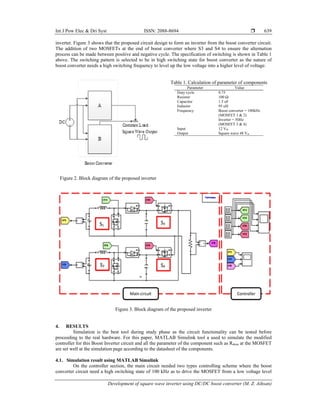
3.1. Proposed inverter design
In SWBI, two Boost Converters will be used and connected to a common load which illustrated in
Figure 2. This connection will be produced a square waveform when conduct alternately which resembles an
4. Int J Pow Elec & Dri Syst ISSN: 2088-8694
Development of square wave inverter using DC/DC boost converter (M. Z. Aihsan)
639
inverter. Figure 3 shows that the proposed circuit design to form an inverter from the boost converter circuit.
The addition of two MOSFETs at the end of boost converter where S3 and S4 to ensure the alternation
process can be made between positive and negative cycle. The specification of switching is shown in Table 1
above. The switching pattern is selected to be in high switching state for boost converter as the nature of
boost converter needs a high switching frequency to level up the low voltage into a higher level of voltage.
Table 1. Calculation of parameter of components
Parameter Value
Duty cycle 0.75
Resistor 100 Ω
Capacitor 1.5 uF
Inductor 95 uH
Frequency Boost converter = 100kHz
(MOSFET 1 & 2)
Inverter = 50Hz
(MOSFET 3 & 4)
Input 12 Vdc
Output Square wave 48 Vac
Figure 2. Block diagram of the proposed inverter
Figure 3. Block diagram of the proposed inverter
4. RESULTS
Simulation is the best tool during study phase as the circuit functionality can be tested before
proceeding to the real hardware. For this paper, MATLAB Simulink tool a used to simulate the modified
controller for this Boost Inverter circuit and all the parameter of the component such as Rdson at the MOSFET
are set well at the simulation page according to the datasheet of the components.
4.1. Simulation result using MATLAB Simulink
On the controller section, the main circuit needed two types controlling scheme where the boost
converter circuit need a high switching state of 100 kHz as to drive the MOSFET from a low voltage level
5. ISSN: 2088-8694
Int J Pow Elec & Dri Syst, Vol. 10, No. 2, June 2019 : 636 – 644
640
into a higher voltage magnitude. The second switching scheme needs a low switching of 50 Hz to ensure that
the generated voltage can alternate between a positive and negative side. The advantage of this topology as it
is just used the switching interval of 50 Hz compared to the conventional H-bridge inverter that used high
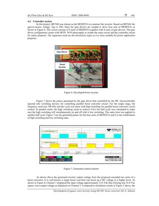
switching state. High switching state will lead to a high switching loss [13]. Table 2 demonstrates the
switching state needed for each MOSFET for the main circuit.
Table 2. Switching state for MOSFET
Power swithces Switching frequency Condition
MOSFET 1 (S1) 100 kHz High Switching State
MOSFET 2 (S2) 100 kHz
MOSFET 3 (S3) 50 Hz Low Switching State
MOSFET 4 (S4) 50 Hz
Figure 4 above demonstrate the pulses generated for MOSFET S1 until MOSFET S4. The pulses are
generated based on the fundamental frequency of 50 Hz and the one complete cycle alternation of the
inverter is 0.02 seconds. The high switching state of 100 kHz driving the MOSFET S1 from 0 until 0.01
second and it is set to off state between 0.01 until 0.02 as to let the second circuit of boost converter operate
at that time. In addition, the switching scheme of MOSFET S3 S4 is purposely designed exactly to be turned
on and turned off exactly at 0.01 and 0.02 seconds as to ensure the alternating process is
successfully achieved. The same sequencing is developed for the hardware section but using the
microcontroller programming
The behavior of boost inverter output voltage shown in Figure 5 above where it shows that the input
voltage is 12 VDC and the output voltage alternate between +44 VDC and -44 VDC. This result has some
distortion where the result should get approximately alternation between +48 VDC and -48 VDC. This
behavior is due to some voltage drop in the component, especially at the capacitor. It can be observed that the
switching is successfully alternate between 0.01 and 0.02 seconds.
Figure 4. Controller scheme for boost inverter circuit
Figure 5. Simulation results of square wave boost inverter
6. Int J Pow Elec & Dri Syst ISSN: 2088-8694
Development of square wave inverter using DC/DC boost converter (M. Z. Aihsan)
641
4.2. Controller section
In this project, IRF540 was chosen as the MOSFETs to construct the inverter. Based on IRF540, the
gate-to-source voltage, Vgs is 20V, there for gate drivers are needed to drive four unit of MOSFETs as
shown in Figure 6. The circuit consists of 4 units of MOSFETs together with 4 units of gate drivers. The gate
driver configuration comes with HCPL 3810 optocoupler to isolate the main circuit and the controller circuit
for safety purposes. The capacitors used are the electrolytic types as it is more suitable for power application
purposes.
Figure 6. Developed boost inverter
Figure 7 shows the pulses generated by the gate driver that controlled by the PIC microcontroller
injected into switching devices for controlling parallel boost converter circuit. For the single stage, the
frequency used was 100 kHz and the cycle was same with high switching for parallel boost converter circuit
control. In parallel mode, the high switching count to achieve 0.01s for half cycle was calculated to make
sure the high switching will simultaneously on and off with it low switching. The same term was applied to
another half cycle. Figure 7 are the generated pulses for the four units of MOSFETs and it is the combination
of high switching and low switching state.
Figure 7. Generated control scheme
As shown above the generated inverter output voltage from the proposed cascaded two units of a
boost converter. It is well known a single boost converter can boost up a DC voltage to a higher level. As
shown in Figure 8, Channel 1 displayed the input voltage approximately 13.6 Vdc thus forming into 52.8 Vac
square wave output voltage as displayed on Channel 2. Compared to simulation results in Figure 5 above, the
7. ISSN: 2088-8694
Int J Pow Elec & Dri Syst, Vol. 10, No. 2, June 2019 : 636 – 644
642
shape of the result is almost the same but the value of output voltage is slightly higher compared to the
simulation as the digital scope read the maximum/amplitude of the output voltage. In Figure 8, it is
noticeable that there is a voltage spike at the beginning of the square wave. With a proper reading and ignore
the voltage spike, the value of output voltage is alternate between +48 VDC and -48 VDC.
The proposed inverter will undergo harmonic performance as to progressively observe the impact of
the combination of DC/DC Boost converter towards the harmonic performance of the inverter. Figure 9
demonstrates the harmonic spectrum using FFT by using Tektronix TPS2014 Digital Oscilloscope.
Figure 8. Input and output voltage for Boost Inverter Figure 9. Harmonic results
The value of harmonic in the developed boost inverter around 48.8% which is slightly higher
compared to the normal square wave inverter mention earlier where it should be in the range of 45%. The
value of harmonic is still acceptable as the difference of range is just 3%.
This circuit is next tested with LC filter to filtering the square wave output voltage. The value of L
and C are decided based on the value of cut-off frequency of 50 Hz and the value of C are set to be constant
and low value as in 4.5 uF and value of inductor 10.7 mH. The value of inductor quite high compared to the
LC filter used in the unipolar inverter as the square wave inverter is hard to be filtered out into sinusoidal due
to the edge of the square wave itself. The filtered output voltage as shown in Figure 10.
Figure 10. Filtered output voltage
It can be observed that the filtering process of the output voltage is nearly unsuccessful as the nature
shape is still in square wave shaped. This is due to the struggle of bending the pure square wave into a
sinusoidal wave shape. Compared to the unipolar inverter, the filtering process is a way easier as there are
many small pulses in the one whole cycle and it will easily bending the curve when entering the LC filter.
The value of peak voltage also drops compare to the square wave after the filtering process. The suitable
capacitors for filtering process are the Cap Film types as the value of ESR in the capacitors very low and
these criteria will help on reducing the voltage stress.
8. Int J Pow Elec & Dri Syst ISSN: 2088-8694
Development of square wave inverter using DC/DC boost converter (M. Z. Aihsan)
643
5. CONCLUSION
The main target is to assembling an alternative topology in inverter by using two Boost Converters
where the proposed inverter can produce a square wave output voltage waveform that resembled the output
of an inverter. The proposed inverter was being utilized when it is using PIC Microcontroller based gate
driver which produce constant gate signal voltage to MOSFETs. The results have proved that the inverter can
provide others mode of operation besides the normal operation that an inverter did. Overall, the project
achieves its goals. This inverter can be further improved as the topology does not need the transformer in
order to level up the small input voltage. The conventional inverter that used H-bridge circuit configurations
needs the transformer to level up the voltage. This configuration simultaneously improves the size of the
inverter as well as the weight of the inverter itself. The design and development of a square wave inverter
using Boost Converters to perform as an inverter was successful.
ACKNOWLEDGEMENTS
The authors would like to acknowledge the financial support from the University Malaysia Perlis. This
research was carried under Short Term Grant 9001-00574.
REFERENCES
[1] B. Wu, Power Conversion and Control of Wind Energy Systems. Piscataway, NJ; Wiley-IEEE Press, 2011
[2] M. E. El-Hawary, Principles of Electric Machines with Power Electronic Applications. Piscataway, NJ; New York,
NY: IEEE Press; Wiley-Interscience, 2002.
[3] D. W. Hart, Power Electronics. Indiana: McGraw Hill, 2011.
[4] S. M. K. Poddar G, “Natural Harmonic Elimination of Square-wave Inverter for Medium-Voltage Application,"
IEEE Trans Power Electron IEEE Transactions on Power Electronics, vol. 24, pp. 1182-1188, 2009.
[5] M. Z. Aihsan, et al., “Design and Implementation of Single-phase Modified SHEPWM Unipolar Inverter,” in 2015
IEEE Conference on Energy Conversion, CENCON 2015, 2016, pp. 337–342.
[6] R. T. Kennedy, Power Electronics: The Enabling Discipline. Kangar: Kolej Universiti Kejuruteraan Utara
Malaysia, 2006.
[7] P. T. Krein, Elements of power electronics. New York: Oxford University Press, 1998.
[8] H. Bing, et al., “Study of a Novel Buck-Boost Inverter for Photovoltaic Systems,” in Electrical Machines and
Systems, 2008. ICEMS 2008. International Conference on, pp. 2602-2606, 2008.
[9] F. L. Y. H. Luo, Power Electronics: Advanced Conversion Technologies. Boca Raton: CRC Press/Taylor &
Francis, 2017.
[10] J. Almazan, et al., “A Comparison Between the Buck, Boost and Buck-Boost Inverters,” in Power Electronics
Congress, 2000. CIEP 2000. VII IEEE International, 2000, pp. 341-346.
[11] A. M. Jamal, “Performance Study of a Modified Sine Wave Inverter,” Engineering and Technology Journal, vol.
28, pp. 399-415, 2018.
[12] M. A. Latif, et al., “Microcontroller based PWM Inverter for Speed Control of a Three Phase Induction Motor, ”
Intern. J. Eng. Technol. International Journal of Engineering and Technology, vol. 5, no. 3, pp. 624-630, 2013.
[13] M. Z. Aihsan, “Lower Side Switching Modification of SHEPWM for Single H-Bridge Unipolar Inverter,” IOP
Conf. Ser. Mater. Sci. Eng., vol. 318, p. 12037, 2018.
9. ISSN: 2088-8694
Int J Pow Elec & Dri Syst, Vol. 10, No. 2, June 2019 : 636 – 644
644
BIBLIOGRAPHY OF AUTHORS
Muhammad Zaid Aihsan received the B.Eng. (Hons) in Industrial Electronic
Engineering and M. Sc Electrical System Engineering degrees from University
Malaysia Perlis, Perlis, Malaysia, in 2013 and 2016, respectively. In May 2016, he
was appointed as lecturer in the Faculty of Engineering Technology under Electrical
Department, Universiti Malaysia Perlis, Malaysia. His research interests include
alternative power converter topologies and control strategies for renewable energy
integration.
Nur Irwany binti Ahmad received the B.Eng. (Hons) in Electrical System
Engineering from University Malaysia Perlis, Perlis Malaysia and M.Eng in
Industrial Electronics and Control engineering from University of Malaya, Bangsar,
Malaysia, in 2014 and 2016, respectively. In August 2016, she was appointed as a
lecturer in the Faculty of Engineering Technology under Electrical Department,
Universiti Malaysia Perlis, Malaysia.Her research interests include renewable energy
systems and electronics control. She is also a member of BEM malaysia.
Wan Azani Mustafa received degree in biomedical electronic engineering (2013) and
PhD in mechatronic engineering (2017) from university malaysia perlis (UniMAP).
Member of Board Engineer Malaysia (BEM) 2014 and Malaysia Board of
Tecnologist (MBOT) (2017). Published more than 40 academic articles and 1 book.
Now, working as a senior lecturer at University Malaysia perlis, Malaysia. Current
interest includes image processing, biomechanics, intelligence system, and control
system.
Norjasmi Abdul Rahman received the B.Eng. (Hons) in Industrial Electronic
Engineering from Universiti Malaysia Perlis in 2007 and MSc (technology) in
electronic and electrical engineering from Aalto University, Finland, in 2010. In July
2010, he was appointed lecturer in the School of Electrical Systems Engineering,
Universiti Malaysia Perlis, Malaysia. He is currently working toward PhD degree at
Denmark Technical University (DTU) in Denmark. His research interests include
dc-dc power conversion, high efficiency step up converters, micro inverter, and
control strategies for renewable energy integration.
Soo Jian Aun received the B.Eng. (Hons) in Industrial Electronic Engineering and
M. Sc Electrical System Engineering degrees from University Malaysia Perlis,
Perlis, Malaysia, in 2014 and 2018, respectively. In May 2016, he was appointed as
lecturer in the Faculty of Engineering Technology under Electrical Department,
Universiti Malaysia Perlis, Malaysia. His research interests include alternative power
converter topologies and control strategies for renewable energy integration.