LIST OF CONTENTS
Introduction
Objective
Literature Review
Problem Formulation
Research Methodology
Results and Analysis
Conclusion
Future Scope
List of Publication
References 2
3.
INTRODUCTION
A powerinverter, or inverter, is a power electronic device or circuitry that
changes direct current (DC) to alternating current (AC).
The input voltage, output voltage and frequency, and overall power
handling depend on the design of the specific device or circuitry.
The inverter does not produce any power; the power is provided by the DC
source. A power inverter can be entirely electronic or may be a combination
of mechanical effects (such as a rotary apparatus) and electronic circuitry.
Power inverters are primarily used in electrical power applications where
high currents and voltages are present; circuits that perform the same
function for electronic signals, which usually have very low currents and
voltages, are called oscillator.
3
4.
• Multilevel invertersexhibit some interesting advantages compared to two-level
VSIs, especially for higher voltage power conversion, where lower switch
voltage stress and lower harmonic content exist.
• A multilevel inverter has been proposed for use in electric vehicles. It makes
EVs more accessible/safer and open wiring possible for most of an EV's
power system because each low voltage (<50 V) battery is isolated through
switching devices.
• In multilevel topologies low voltage switches can be used instead of high voltage
switches as in two-level inverters.
• Low voltage switches are normally smaller and cheaper and they can handle
higher switching frequencies.
4
MULTI-LEVEL INVERTER
5.
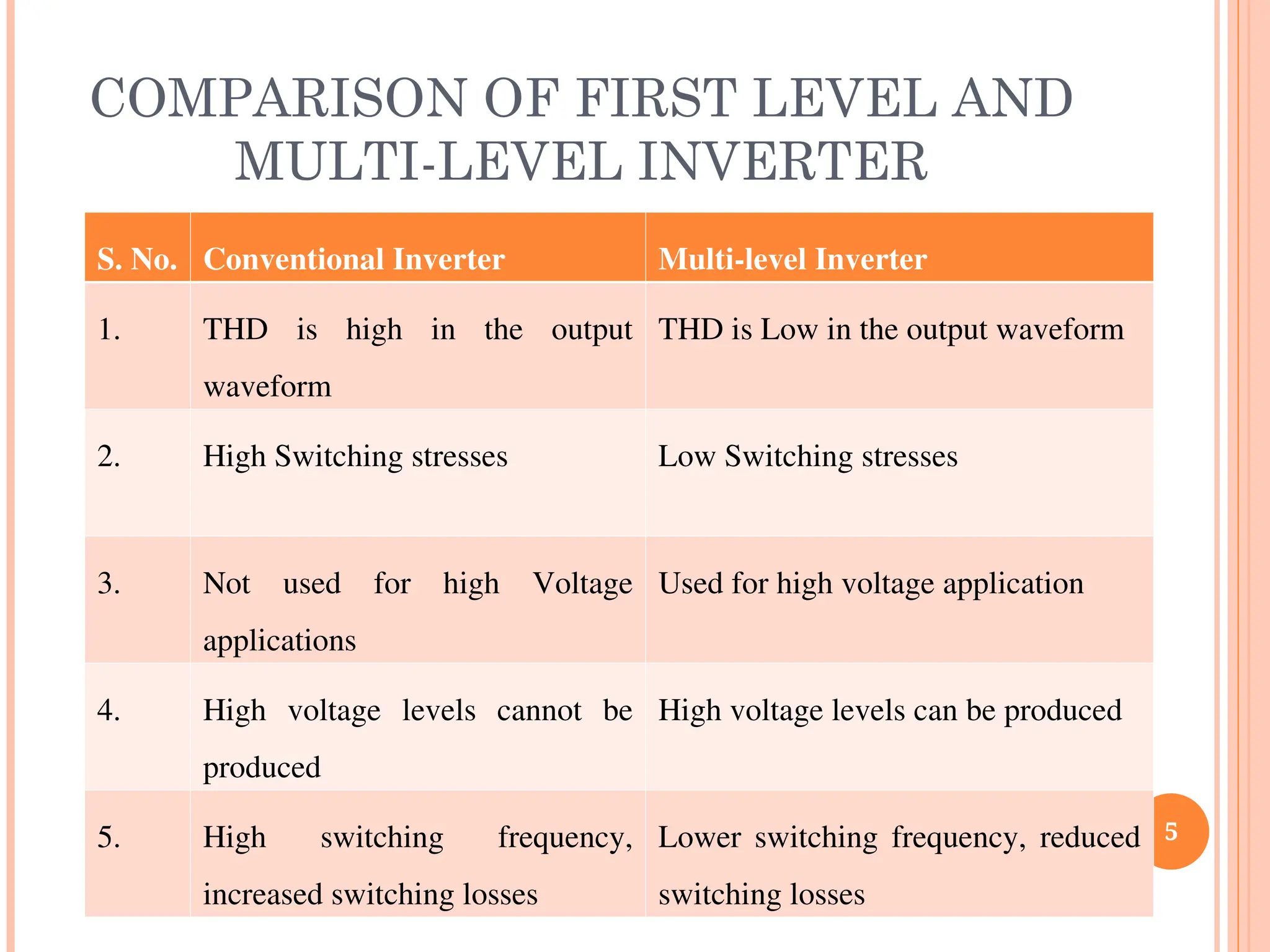
COMPARISON OF FIRSTLEVEL AND
MULTI-LEVEL INVERTER
5
S. No. Conventional Inverter Multi-level Inverter
1. THD is high in the output
waveform
THD is Low in the output waveform
2. High Switching stresses Low Switching stresses
3. Not used for high Voltage
applications
Used for high voltage application
4. High voltage levels cannot be
produced
High voltage levels can be produced
5. High switching frequency,
increased switching losses
Lower switching frequency, reduced
switching losses
6.
In anelectric power system, a harmonic is a voltage or current at a multiple
of the fundamental frequency of the system, produced by the action of non-
linear loads such as rectifiers, discharge lighting, or saturated magnetic
devices.
Harmonic frequencies in the power grid are a frequent cause of power
quality problems.
Harmonics in power systems result in increased heating in the equipment
and conductors, misfiring in variable speed drives, and torque pulsations in
motors.
6
TOTAL HARMONIC DISTORTION
7.
7
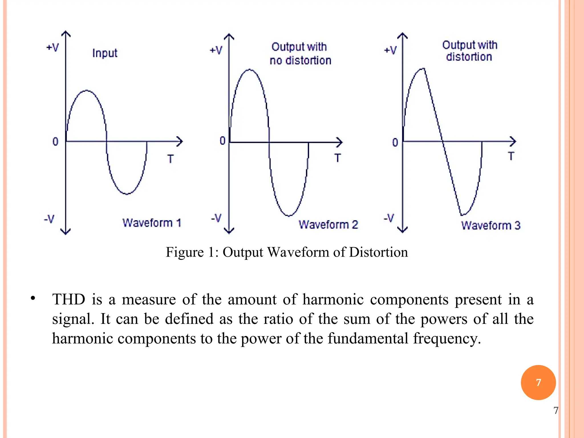
Figure 1: OutputWaveform of Distortion
• THD is a measure of the amount of harmonic components present in a
signal. It can be defined as the ratio of the sum of the powers of all the
harmonic components to the power of the fundamental frequency.
7
8.
PHOTOVOLTAIC ARRAY
•Again thepower produced by a single module is not sufficient to meet the
power demands for most of the practical purposes.
•PV arrays can use inverters to convert the dc output into ac and use it for
motors, lighting and other loads.
•The modules are connected in series for more voltage rating and then in
parallel to meet the current specifications.
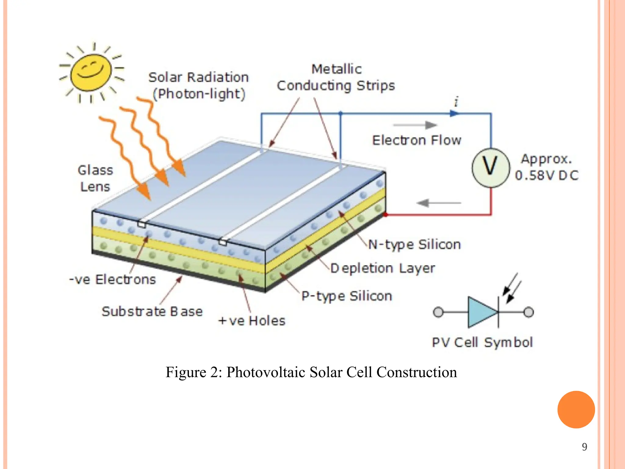
•When sunlight shines on a photovoltaic cell, photons of light strike the surface
of the semiconductor material and liberate electrons from their atomic bonds.
8
OBJECTIVE
The main contributionsof this work will be summarized as follows.
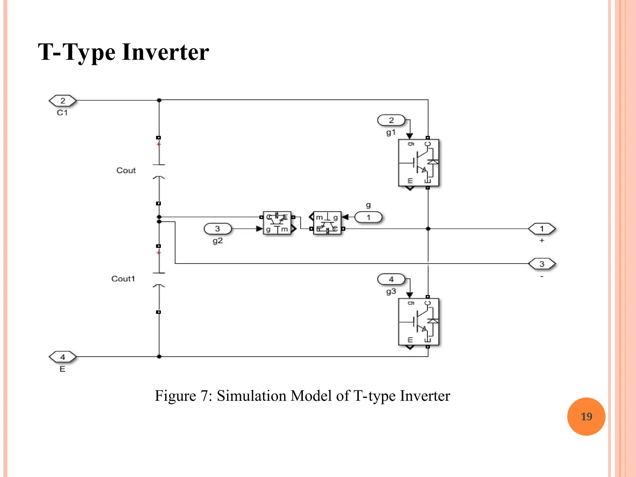
• To design Switched Capacitor Based Multilevel Inverter using T-type is
simulated using Simulink MATLAB R2015a Software.
• To improve THD and minimize switch count in multi-level inverter
with the t-type topology.
• Present model make it suited for electric vehicle.
10
11.
LITERATURE REVIEW
11
Y. Q.Wang et al. (2021, [1]), a novel switched-capacitor-based T-type
multilevel inverter (MLI) is proposed in this paper. In addition to
achieving a lower maximum voltage stress on the switches than the input
voltage, the proposed inverter also has the ability to boost voltage, making
it suitable for high-voltage applications. It is important to point out that the
proposed inverter has two topology extension schemes that help it get a
higher voltage gain and output level. A seven-level inverter can be
constructed with just two capacitors thanks to the advantages of low
voltage stress and low power consumption.
Ruijie Sun et al. (2020, [2]), have proposes a novel single-phase boosting
five-level inverter with fewer parts and simple control for use with electric
vehicles (EVs) and renewable energy systems. The inverter has one diode,
one capacitor, nine power transistors, and supplies power from a dc
voltage source. To double the voltage gain, all you need are five
independent control signals. The value of the input voltage matches the
peak inverse voltages across each switch.
12.
12
Y. Q. Wanget al. (2020, [3]), the large number of devices and
complicated expansion of conventional multilevel inverters cause issues.
A modular expanded multilevel inverter that can effectively simplify
expansion and reduce the number of devices is proposed in this paper.
The voltage-dividing capacitors can be guaranteed to be voltage-balanced
by the proposed inverter. The inverter is able to achieve high output
voltage levels and voltage gain thanks to the cascading of the T-type
switched capacitor module and the step-by-step charging method of the
switched capacitors. Additionally, the inversion can be accomplished
without the H-bridge, resulting in a significant decrease in the switches'
total standing voltage.
S. Habib et al. (2020, [4]), in order to develop dependable and effective
charging solutions for electric vehicles (EVs), the transportation sector
needs new options for power electronics converters. The desire to reduce
gasoline consumption and increase the battery capacity for greater electric
range for EVs is feasible in the near future thanks to the ongoing
development of power electronics converters. Since a power electronics
converter serves as the primary interface between the power network and
the EV battery system, new low-cost and high-reliability power
converters are needed for the advanced charging mechanism of EVs.
13.
13
P. Wang etal. (2020, [5]), due to the noise caused by fast switching
power electronics, inverter-fed motors' partial discharge (PD) is more
complicated than that of conventional sinusoidal voltage-operated
motors. This is because impulsive voltages generated at a high
frequency and with a short rise time are generated by inverters. At
conditions of repeated impulsive voltage, the currently available PD
sensors as well as related technology for sinusoidal and DC voltage
cannot be utilized. In order to detect PD for impulsive voltage, the
design of an antenna with optimized geometry and satisfied parameters
will be reported in this work. The antenna is checked, and the test
configuration and impulse voltage parameters' effects on PD features are
talked about.
14.
PROBLEM IDENTIFICATION
Tremendousresearch efforts have been devoted to developing ANPC
inverters with a higher number of levels, but at the expense of the voltage-
balancing problem. Additional voltage-balancing circuits with especially
designed control algorithms are normally necessary to resolve the balancing
problem.
With the required minimum dc link voltage Vdc twice the ac grid peak
voltage, a boost dc–dc converter is essential to generate the demanded dc-
link voltage. However, this two-stage power conversion structure reduces
the efficiency of the system.
14
15.
15
RESEARCH METHODOLOGY
• Anexhaustive assessment of the literature is presented with the goal of
decreasing the number of devices required to support an increased
number of output levels.
• Nowadays, investments in new renewable and sustainable energy sectors
are being rapidly carried out to reduce CO2 emissions and address global
warming caused by the use of fossil fuels.
• Advances in power electronics have contributed greatly to the advent of
solar photovoltaic and wind energy-based power generation systems.
18
Boost Inverter
+
-
S1
D
S2 S3
VDC
C
VDC
+- a
b
Vab +
-
S3
S1 S2
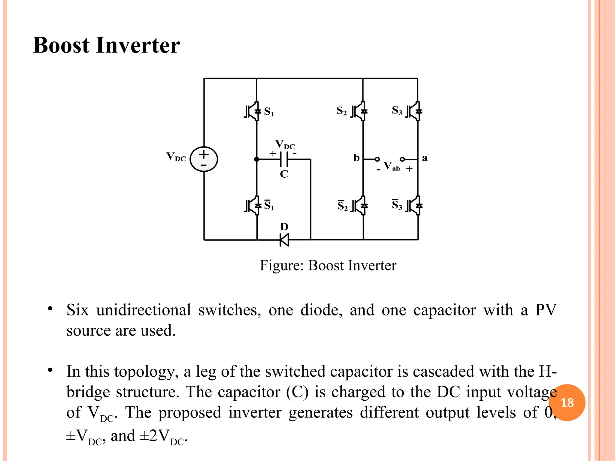
Figure: Boost Inverter
• Six unidirectional switches, one diode, and one capacitor with a PV
source are used.
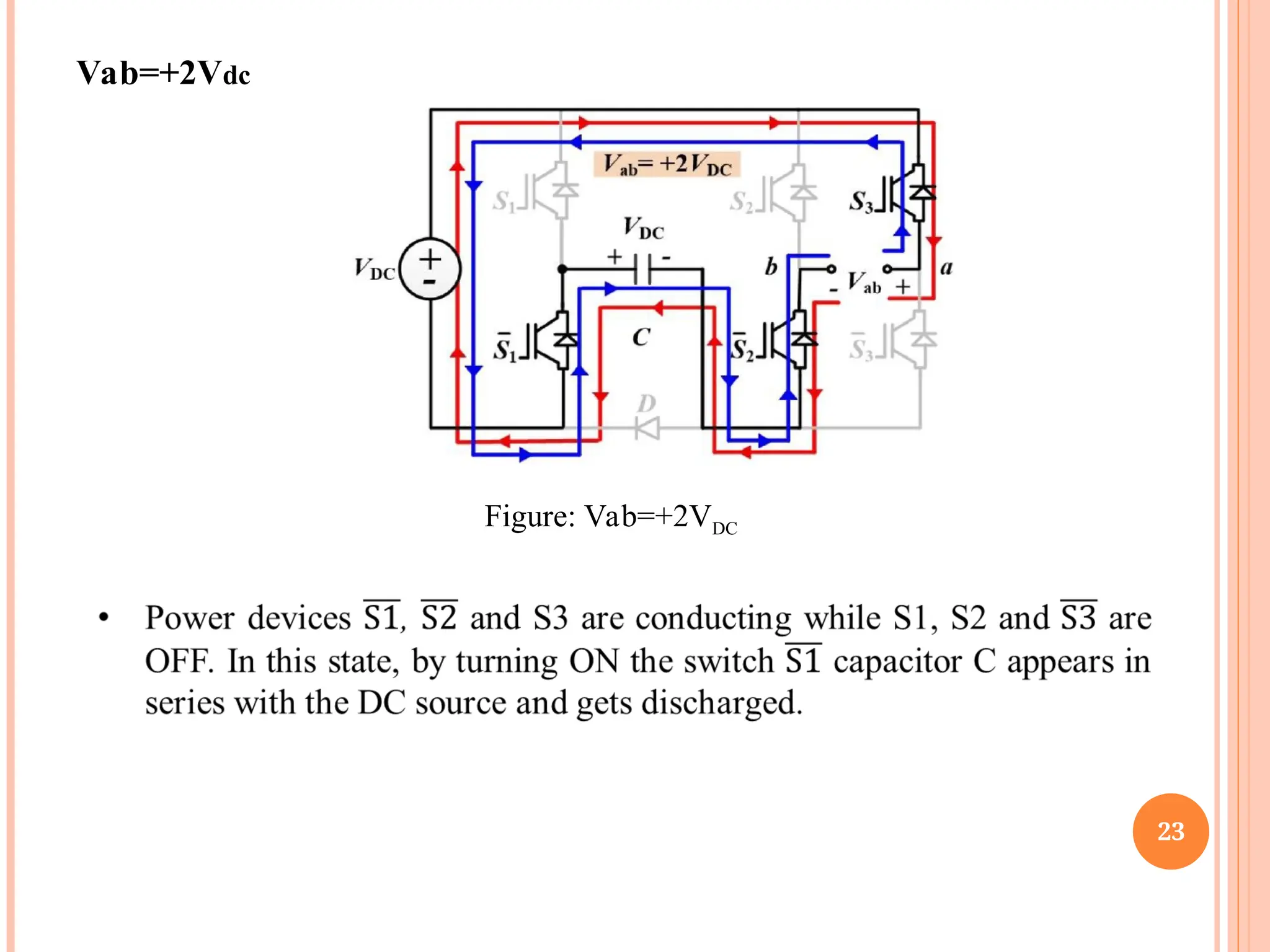
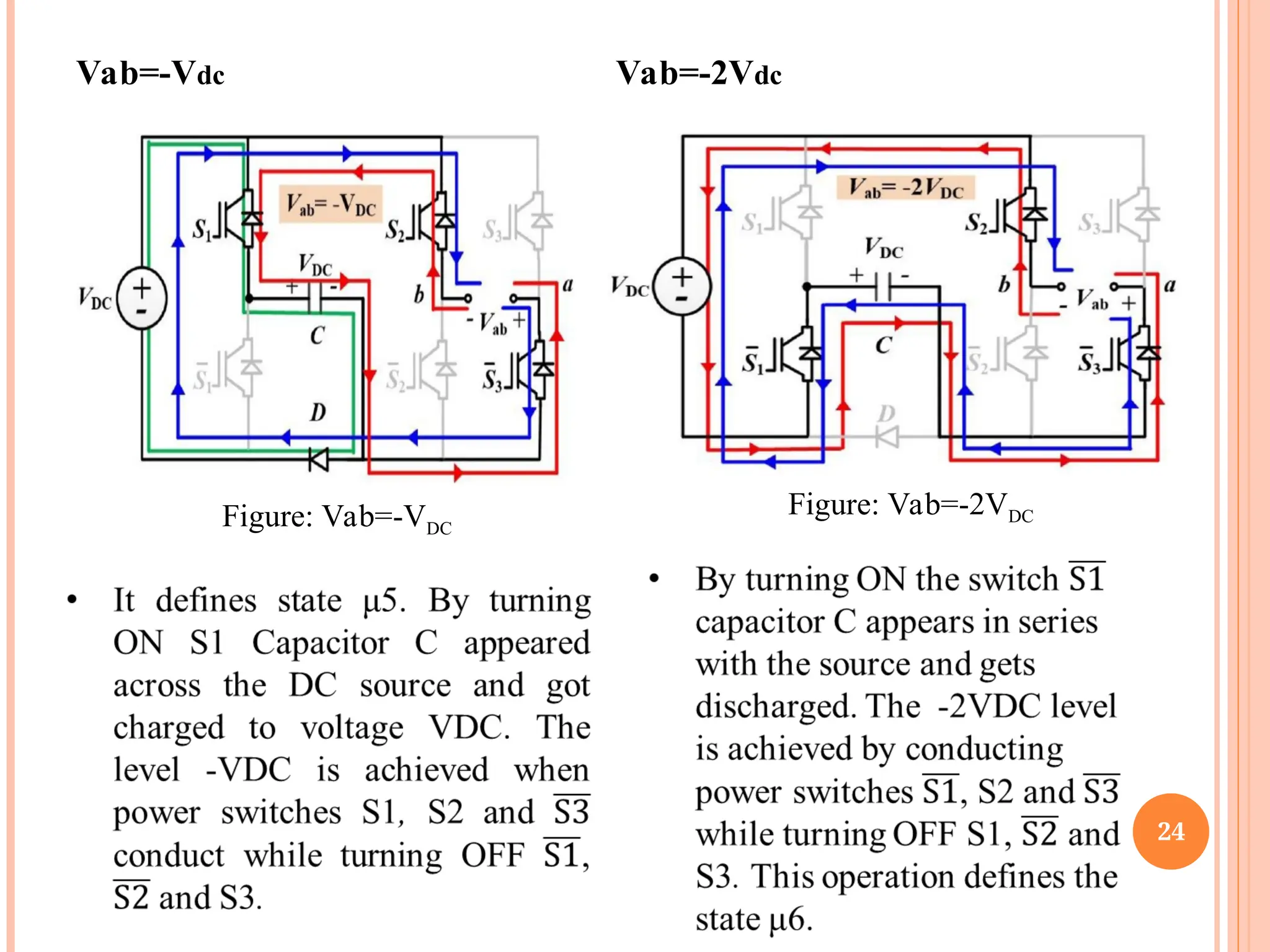
• In this topology, a leg of the switched capacitor is cascaded with the H-
bridge structure. The capacitor (C) is charged to the DC input voltage
of VDC. The proposed inverter generates different output levels of 0,
±VDC, and ±2VDC.
20
20
Working of BoostInverter
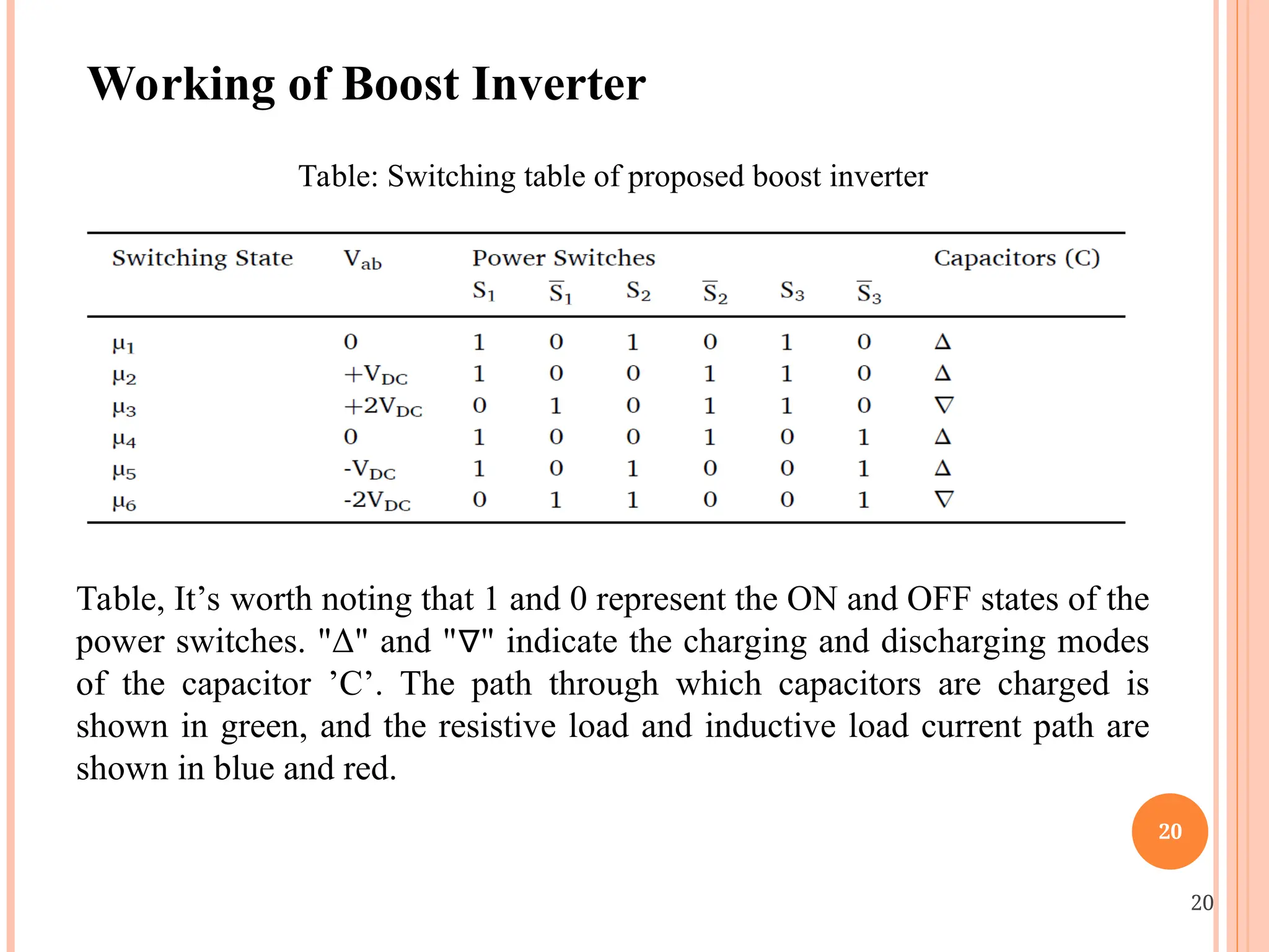
Table: Switching table of proposed boost inverter
Table, It’s worth noting that 1 and 0 represent the ON and OFF states of the
power switches. "Δ" and " " indicate the charging and discharging modes
∇
of the capacitor ’C’. The path through which capacitors are charged is
shown in green, and the resistive load and inductive load current path are
shown in blue and red.
25
SELF-BALANCING MECHANISMS OFCAPACITOR
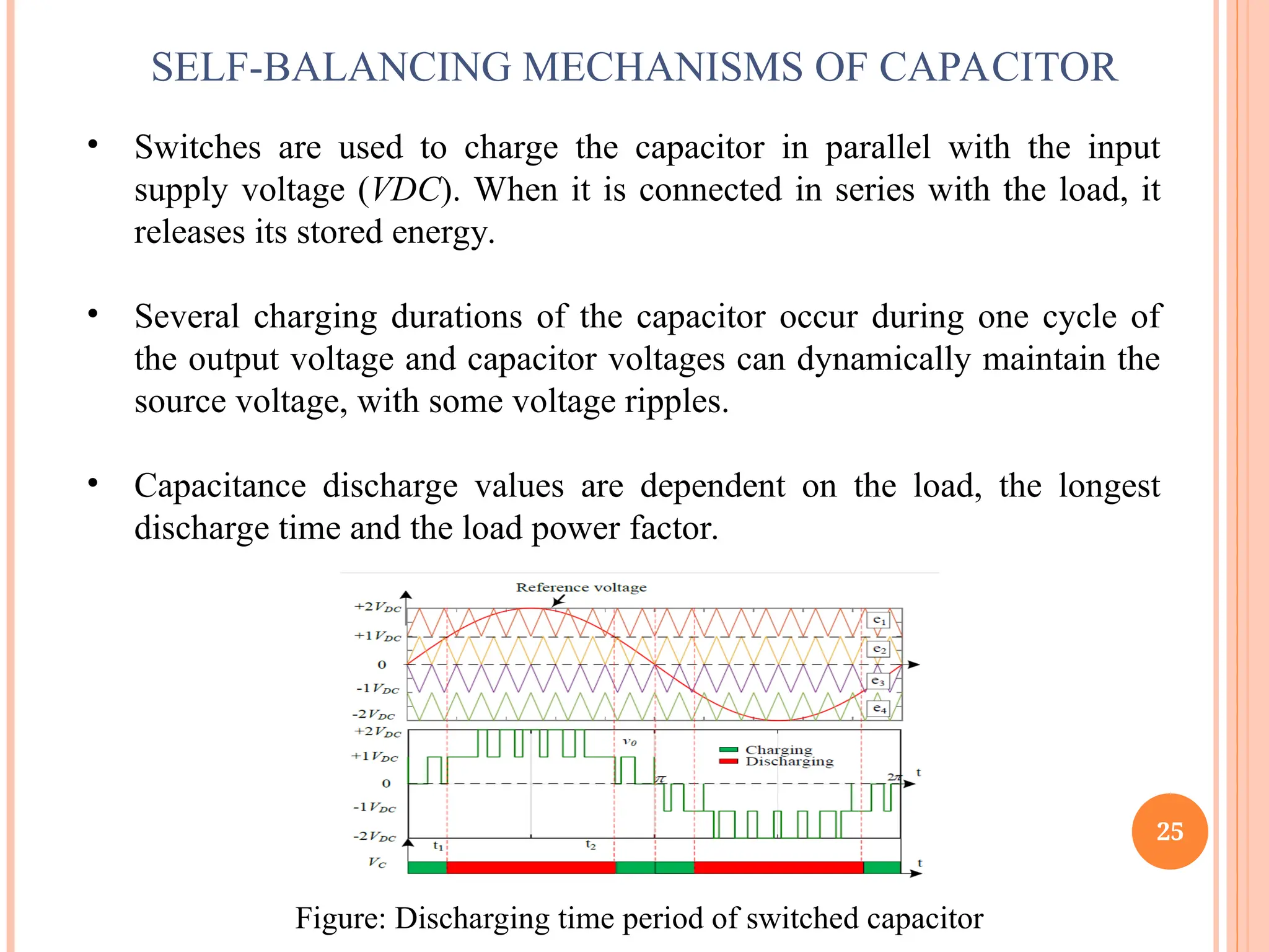
• Switches are used to charge the capacitor in parallel with the input
supply voltage (VDC). When it is connected in series with the load, it
releases its stored energy.
• Several charging durations of the capacitor occur during one cycle of
the output voltage and capacitor voltages can dynamically maintain the
source voltage, with some voltage ripples.
• Capacitance discharge values are dependent on the load, the longest
discharge time and the load power factor.
Figure: Discharging time period of switched capacitor
26.
26
SIMULATION RESULTS
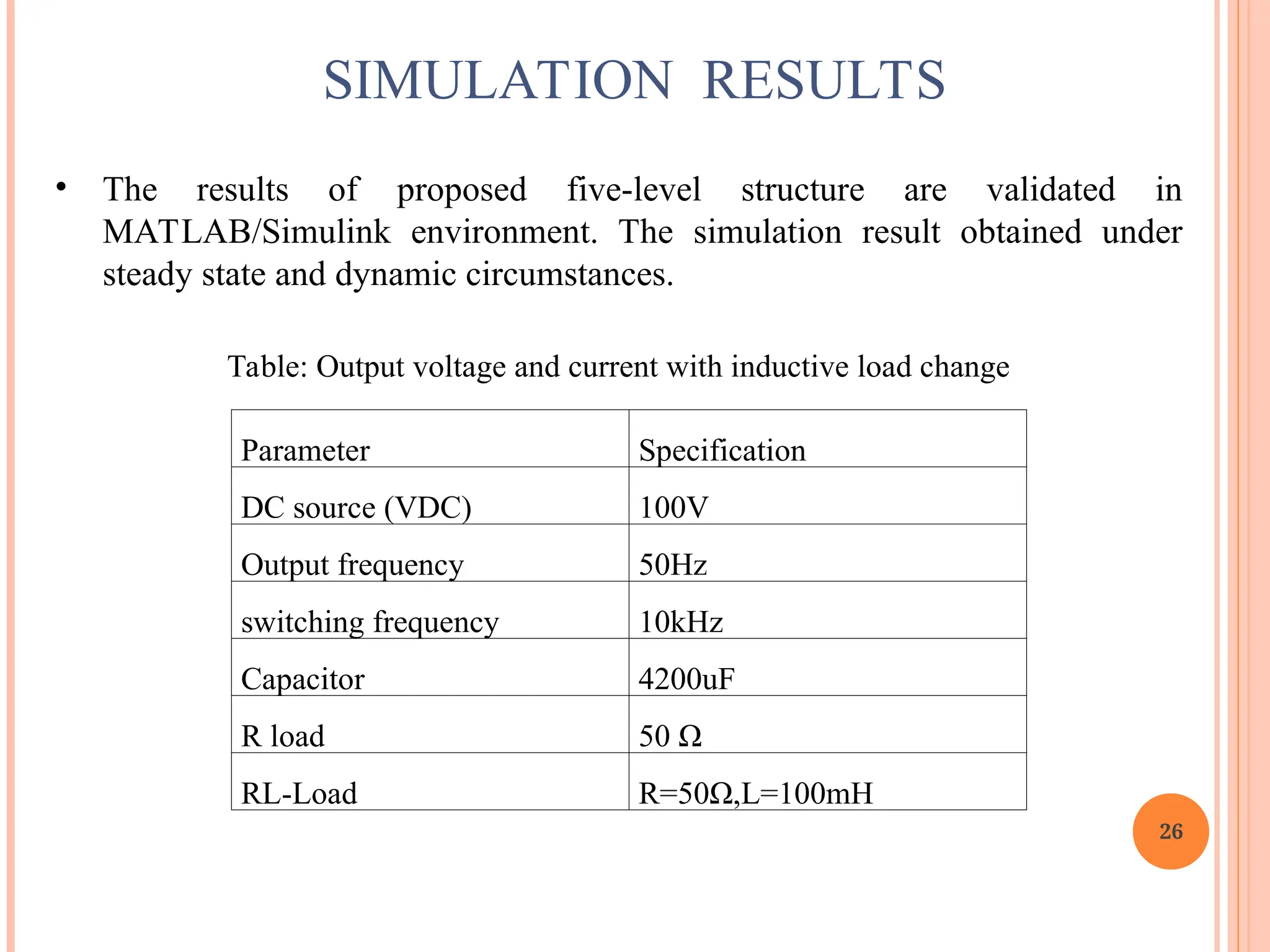
• Theresults of proposed five-level structure are validated in
MATLAB/Simulink environment. The simulation result obtained under
steady state and dynamic circumstances.
Table: Output voltage and current with inductive load change
Parameter Specification
DC source (VDC) 100V
Output frequency 50Hz
switching frequency 10kHz
Capacitor 4200uF
R load 50 Ω
RL-Load R=50Ω,L=100mH
34
COMPARISON RESULT
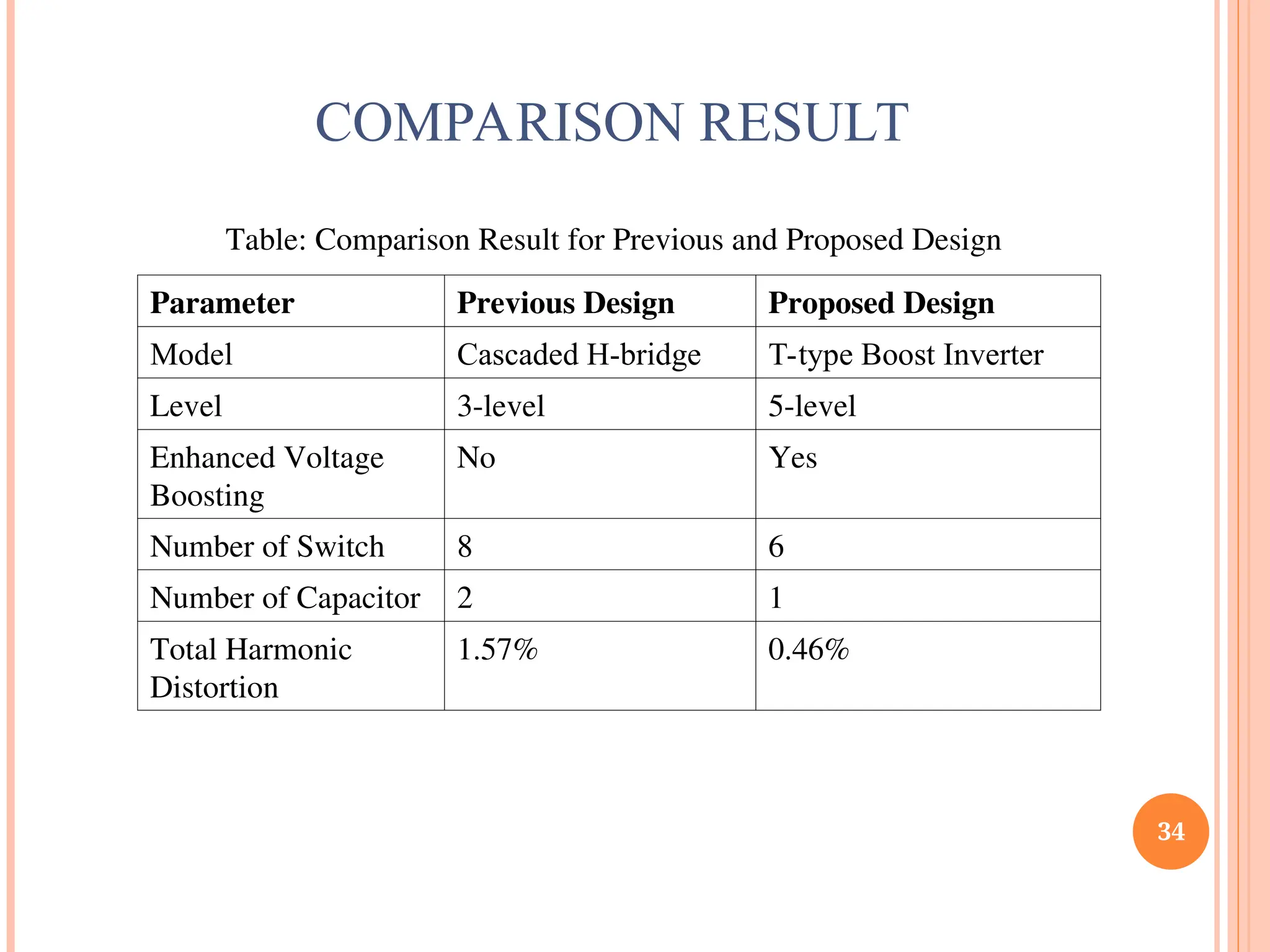
Table: ComparisonResult for Previous and Proposed Design
Parameter Previous Design Proposed Design
Model Cascaded H-bridge T-type Boost Inverter
Level 3-level 5-level
Enhanced Voltage
Boosting
No Yes
Number of Switch 8 6
Number of Capacitor 2 1
Total Harmonic
Distortion
1.57% 0.46%
35.
35
• In thisintense the inductive load change from 100Ohm 200mH to 50Ohm
100mH at the time of 0.5sec. It can be clearly seen that the output voltage
has not change at this time but output current has been doubled at this point.
Its changes from 1.5A to the 3A after doing half of the inductive load.
• In this intense the inductive load change from 100Ohm 100mH to pure
resistive load 50Ohm at the time of 0.5sec.
• It can be clearly seen that the output voltage has not change at this time but
output current has been doubled at this point. Its changes from 1.8A
inductive current to the 4A resistive current after doing change the load.
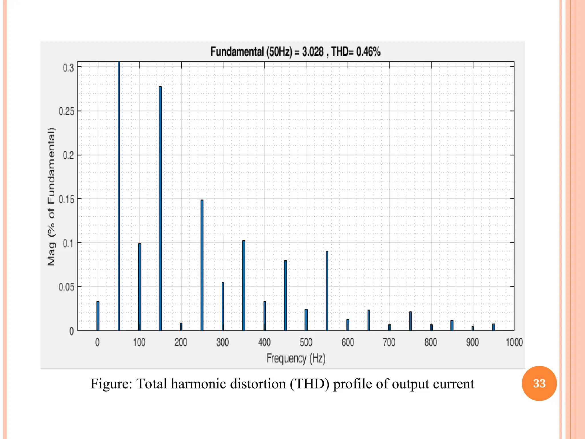
• Its achieves a minimum value of the THD i.e., 0.46% that is good enough to
use for the grid and also can be used for the different load applications.
CONCLUSIONS
36.
36
The following specificareas are suggested for further research.
•The further implementation of proposed algorithm system such as nine and
eleven stage on the AC-DC converter.
•Different multicarrier PWM techniques can be investigated for dual T types
boost ANPC inverter.
•A cost effective MPPT technique can be developed and analyzed through
simulation and hardware.
FUTURE SCOPES
37.
1. Y. Q.Wang Y. S. Yuan G. Li Y. M. Ye K. W. Wang and J. Liang "A T-type switched-capacitor multilevel
inverter with low voltage stress and self-balancing" IEEE Transactions on Circuits and Systems I: Regular
Papers vol. 68 no. 5 pp. 2257-2270 May 2021.
2. Ruijie Sun, Yuanmao Ye and Xiaolin Wang, “A Novel Five-Level Boosting Inverter With Self- Balancing
Switched-Capacitor for Electric Vehicles”, 8th International Conference on Power Electronics Systems and
Applications (PESA), IEEE 2020.
3. Y. Q. Wang Y. S. Yuan G. Li T. J. Chen K. W. Wang and J. Liang "A generalized multilevel inverter based on
T-type switched capacitor module with reduced devices" Energies vol. 13 no. 17 pp. 4406 Aug. 2020.
4. S. Habib M. M. Khan F. Abbas A. Ali M. T. Faiz F. Ehsan et al. "Contemporary trends in power electronics
converters for charging solutions of electric vehicles" CSEE Journal of Power and Energy Systems vol. 6 no. 4
pp. 911-929 Dec. 2020.
5. P. Wang S. J. Ma S. Akram K. Zhou Y. D. Chen and M. T. Nazir "Design of archimedes spiral antenna to
optimize for partial discharge detection of inverter fed motor insulation" IEEE Access vol. 8 pp. 193202-
193213 Nov. 2020.
6. J. Zeng W. J. Lin D. H. Cen and J. F. Liu "Novel K-type multilevel inverter with reduced components and self-
balance" IEEE Journal of Emerging and Selected Topics in Power Electronics vol. 8 no. 4 pp. 4343-4354 Dec.
2020.
7. W. J. Lin J. Zeng J. F. Liu Z. X. Yan and R. J. Hu "Generalized symmetrical step-up multilevel inverter using
crisscross capacitor units" IEEE Transactions on Industrial Electronics vol. 67 no. 9 pp. 7439-7450 Sep. 2020.
8. K. P. Panda P. R. Bana and G. Panda "A switched-capacitor self-balanced high-gain multilevel inverter
employing a single DC source" IEEE Transactions on Circuits and Systems II: Express Briefs vol. 67 no. 12
pp. 3192-3196 Dec. 2020.
9. M. Ghodsi and S. M. Barakati "New generalized topologies of asym-metric modular multilevel inverter based
on six-switch H-bridge" Inter-national Journal of Circuit Theory and Applications vol. 48 no. 5 pp. 789-808
May 2020.
10. M. Ghodsi and S. M. Barakati "A generalized cascade switched-capacitor multilevel converter structure and its
optimization analysis" IEEE Journal of Emerging and Selected Topics in Power Electronics vol. 8 no. 4 pp.
4306-4317 Dec. 2020.
37
REFERENCES
38.
11. AbderezakLashab, DezsoSera , Frederik Hahn , Luis Camurca, YacineTerriche, Marco Liserre, and Josep
M. Guerrero, “Cascaded Multilevel PV Inverter With Improved Harmonic Performance During Power
Imbalance Between Power Cells”, IEEE Transactions on Industry Applications, Vol. 56, No. 3, May/June
2020.
12. W. Peng Q. Ni X. Qiu and Y. Ye "Seven-Level Inverter With Self-Balanced Switched-Capacitor and Its
Cascaded Extension" IEEE Trans. Power Electron. vol. 34 no. 12 pp. 11889-11896 Dec. 2019.
13. M. Saeedian M. E. Adabi S. M. Hosseini J. Adabi and E. Pouresmaeil "A Novel Step-Up Single Source
Multilevel Inverter: Topology Operating Principle and Modulation" IEEE Trans. Power Electron. vol. 34
no. 4 pp. 3269-3282 April 2019.
14. J. Liu W. Lin J. Wu and J. Zeng "A Novel Nine-Level Quadruple Boost Inverter with Inductive-load
Ability" IEEE Trans. Power Electron. vol. 34 no. 5 pp. 4014-4018 May 2019.
15. W. Peng Q. Ni X. H. Qiu and Y. M. Ye "Seven-level inverter with self-balanced switched-capacitor and its
cascaded extension" IEEE Transactions on Power Electronics vol. 34 no. 12 pp. 11889-11896 Dec. 2019.
16. R. Barzegarkhoo M. Moradzadeh and F. Blaabjerg "A new boost switched-capacitor multilevel converter
with reduced circuit devices" IEEE Trans. Power Electron. vol. 33 no. 8 pp. 6738-6754 Aug. 2018.
17. M. Saeedian S. M. Hosseini and J. Adabi "A Five-Level Step-Up Module for Multilevel Inverters: Topology
Modulation Strategy and Implementation" IEEE J. Emerg. Sel. Top. Power Electron. vol. 6 no. 4 pp. 2215-
2226 Dec. 2018.
18. A. Taghvaie J. Adabi and M. Rezanejad "A Self-Balanced Step-Up Multilevel Inverter Based on Switched-
Capacitor Structure" IEEE Trans. Power Electron. vol. 33 no. 1 pp. 199-209 Jan. 2018.
19. S. S. Lee "Single-Stage Switched-Capacitor Module (S3CM) Topology for Cascaded Multilevel Inverter"
IEEE Trans. Power Electron. vol. 33 no. 10 pp. 8204-8207 Oct. 2018.
20. M. Norambuena S. Kouro S. Dieckerhoff and J. Rodriguez "Reduced multilevel converter: A novel
multilevel converter with a reduced number of active switches" IEEE Transactions on Industrial Electronics
vol. 65 no. 5 pp. 3636-3645 May 2018.
38
39.
39
21. N. SusheelaP. S. Kumar and S. K. Sharma "Generalized algorithm of reverse mapping based
SVPWM strategy for diode-clamped multilevel inverters" IEEE Transactions on Industry
Applications vol. 54 no. 3 pp. 2425-2437 May/Jun 2018.
22. R. Barzegarkhoo M. Moradzadeh E. Zamiri H. M. Kojabadi and F. Blaabjerg "A new boost
switched-capacitor multilevel converter with reduced circuit devices" IEEE Transactions on Power
Electronics vol. 33 no. 8 pp. 6738-6754 Aug. 2018.
23. Y. T. Lei C. Barth S. B. Qin W. C. Liu I. Moon A. Stillwell et al. "A 2-kW single-phase seven-level
flying capacitor multilevel inverter with an active energy buffer" IEEE Transactions on Power
Electronics vol. 32 no. 11 pp. 8570-8581 Nov. 2017.
24. J. F. Liu J. L. Wu J. Zeng and H. F. Guo "A novel nine-level inverter employing one voltage source
and reduced components as high-frequency AC power source" IEEE Transactions on Power
Electronics vol. 32 no. 4 pp. 2939-2947 Apr. 2017.
25. F. Rong X. Gong and S. Huang "A novel grid-connected PV system based on MMC to get the
maximum power under partial shading conditions" IEEE Trans. Power Electron. vol. 32 no. 6 pp.
4320-4333 Jun. 2017.
26. H. Wang, L. Kou, Y.-F. Liu, and P. C. Sen, “A seven-switch five-level active-neutral-point-clamped
converter and its optimal modulation strategy,” IEEE Trans. Power Electron., vol. 32, no. 7, pp.
5146–5161, Jul. 2017.
27. G. Farivar B. Hredzak and V. G. Agelidis "A dc-side sensorless cascaded H-bridge multilevel
converter-based photovoltaic system" IEEE Trans. Ind. Electron. vol. 63 no. 7 pp. 4233-4241 Jul.
2016.
28. Y. Yu G. Konstantinou B. Hredzak and V. G. Agelidis "Power balance of cascaded H-bridge
multilevel converters for large-scale photovoltaic integration" IEEE Trans. Power Electron. vol. 31
no. 1 pp. 292-303 Jan. 2016.
29. J. I. Leon S. Kouro L. G. Franquelo J. Rodriguez and B. Wu "The essential role and the continuous
evolution of modulation techniques for voltage-source inverters in the past present and future power
electronics" IEEE Trans. Ind. Electron. vol. 63 no. 5 pp. 2688-2701 May 2016.
30. Y. Yu G. Konstantinou B. Hredzak and V. G. Agelidis "Operation of cascaded H-bridge multilevel
converters for large-scale photovoltaic power plants under bridge failures" IEEE Trans. Ind.
Electron. vol. 62 no. 11 pp. 7228-7236 Nov. 2015.
40.
40
31. H. SnaniM. Amarouayache A. Bouzid A. Lashab and H. Bounechba "A study of dynamic behaviour
performance of DC/DC boost converter used in the photovoltaic system" Proc. IEEE 15th Int. Conf.
Environ. Elect. Eng. pp. 1966-1971 2015.
32. Bayhan, S & Abu-Rub, H 2015, 'Model predictive control of quasi-z source three-phase four-leg
inverter', in 41st Annual Conference of the IEEE Industrial Electronics Society, IECON 2015, pp.
362-367.
33. R. J. Wai, C. Y. Lin, C. Y. Lin, R. Y. Ouan, and Y. R. Chang, "High efficiency power conversion
system for kilowatt-level stand-alone generation unit with low input voltage," IEEE Irans. Ind.
Electron. vol. 55, no. 10, pp. 3702- 3714, Oct. 2008.
34. L. S. Yang, T. J. Liang, and J. F. Chen, 'Transformer-Iess dc- dc converter with high voltage gain,
"IEEE Irans. Ind. Electron. vol. 56, no. 8,pp. 3144- 3152, Aug. 2009.
35. F. L. Luo and H. Ye, "Positive output super-lift converters, "IEEE Irans. Power Electron. vol. 18, no.
I , pp. 05- 113, Jan. 2003.
36. T. F. Wu, Y. S. Lai, 1. C. Hung, and Y. M. Chen, "Boost converter with coupled inductors and buck-
boost type of active clamp, "IEEE Irans. Ind. Electron. vol. 55, no. I , pp. 154-162, Jan. 2008.
37. D. C. Lee and D. S. Lim, “AC voltage and current sensorless control of three-phase PWM rectifiers,”
IEEE Trans. Power Electron., vol. 17, no. 6, pp. 883–890, Oct. 2002.
38. J. Rodr´ıguez et al., “PWM regenerative rectifiers: State of the art,” IEEE Trans. Ind. Electron., vol.
52, no. 1, pp. 5–22, Feb. 2005.
39. N. Zargari and G. Joos, “Performance investigation of a currentcontrolled voltage-regulated PWM
rectifier in rotating and stationary frames,” IEEE Trans. Ind. Electron., vol. 42, no. 4, pp. 396–401,
Aug. 1995.
40. Calais, M, Agelidis, VG &Dymond, MS 2001, 'A cascaded inverter for transformerless single-phase
grid-connected photovoltaic systems', Renew Energy, vol. 22, no. 1, pp. 255-262.
![LITERATURE REVIEW
11
Y. Q. Wang et al. (2021, [1]), a novel switched-capacitor-based T-type
multilevel inverter (MLI) is proposed in this paper. In addition to
achieving a lower maximum voltage stress on the switches than the input
voltage, the proposed inverter also has the ability to boost voltage, making
it suitable for high-voltage applications. It is important to point out that the
proposed inverter has two topology extension schemes that help it get a
higher voltage gain and output level. A seven-level inverter can be
constructed with just two capacitors thanks to the advantages of low
voltage stress and low power consumption.
Ruijie Sun et al. (2020, [2]), have proposes a novel single-phase boosting
five-level inverter with fewer parts and simple control for use with electric
vehicles (EVs) and renewable energy systems. The inverter has one diode,
one capacitor, nine power transistors, and supplies power from a dc
voltage source. To double the voltage gain, all you need are five
independent control signals. The value of the input voltage matches the
peak inverse voltages across each switch.](https://image.slidesharecdn.com/1-250614175242-5244821c/75/Switched-Capacitor-Based-Multilevel-Inverter-With-Reduced-Device-Counts-For-Electric-Vehicles-11-2048.jpg)
![12
Y. Q. Wang et al. (2020, [3]), the large number of devices and
complicated expansion of conventional multilevel inverters cause issues.
A modular expanded multilevel inverter that can effectively simplify
expansion and reduce the number of devices is proposed in this paper.
The voltage-dividing capacitors can be guaranteed to be voltage-balanced
by the proposed inverter. The inverter is able to achieve high output
voltage levels and voltage gain thanks to the cascading of the T-type
switched capacitor module and the step-by-step charging method of the
switched capacitors. Additionally, the inversion can be accomplished
without the H-bridge, resulting in a significant decrease in the switches'
total standing voltage.
S. Habib et al. (2020, [4]), in order to develop dependable and effective
charging solutions for electric vehicles (EVs), the transportation sector
needs new options for power electronics converters. The desire to reduce
gasoline consumption and increase the battery capacity for greater electric
range for EVs is feasible in the near future thanks to the ongoing
development of power electronics converters. Since a power electronics
converter serves as the primary interface between the power network and
the EV battery system, new low-cost and high-reliability power
converters are needed for the advanced charging mechanism of EVs.](https://image.slidesharecdn.com/1-250614175242-5244821c/75/Switched-Capacitor-Based-Multilevel-Inverter-With-Reduced-Device-Counts-For-Electric-Vehicles-12-2048.jpg)
![13
P. Wang et al. (2020, [5]), due to the noise caused by fast switching
power electronics, inverter-fed motors' partial discharge (PD) is more
complicated than that of conventional sinusoidal voltage-operated
motors. This is because impulsive voltages generated at a high
frequency and with a short rise time are generated by inverters. At
conditions of repeated impulsive voltage, the currently available PD
sensors as well as related technology for sinusoidal and DC voltage
cannot be utilized. In order to detect PD for impulsive voltage, the
design of an antenna with optimized geometry and satisfied parameters
will be reported in this work. The antenna is checked, and the test
configuration and impulse voltage parameters' effects on PD features are
talked about.](https://image.slidesharecdn.com/1-250614175242-5244821c/75/Switched-Capacitor-Based-Multilevel-Inverter-With-Reduced-Device-Counts-For-Electric-Vehicles-13-2048.jpg)
![27
Voltage
[V]
Current
[A]
Time [sec]
Figure: Output voltage and current with resistive load](https://image.slidesharecdn.com/1-250614175242-5244821c/75/Switched-Capacitor-Based-Multilevel-Inverter-With-Reduced-Device-Counts-For-Electric-Vehicles-27-2048.jpg)
![28
Voltage
[V]
Current
[A]
Time [sec]
Figure: Output voltage and current with inductive load](https://image.slidesharecdn.com/1-250614175242-5244821c/75/Switched-Capacitor-Based-Multilevel-Inverter-With-Reduced-Device-Counts-For-Electric-Vehicles-28-2048.jpg)
![29
Voltage
[V]
Time [sec]
Figure: Capacitor voltage](https://image.slidesharecdn.com/1-250614175242-5244821c/75/Switched-Capacitor-Based-Multilevel-Inverter-With-Reduced-Device-Counts-For-Electric-Vehicles-29-2048.jpg)
![30
Voltage
[V]
Current
[A]
Time [sec]
Figure: Output voltage and current with resistive load change](https://image.slidesharecdn.com/1-250614175242-5244821c/75/Switched-Capacitor-Based-Multilevel-Inverter-With-Reduced-Device-Counts-For-Electric-Vehicles-30-2048.jpg)
![31
Voltage
[V]
Current
[A]
Time [sec]
Figure: Output voltage and current with inductive load change](https://image.slidesharecdn.com/1-250614175242-5244821c/75/Switched-Capacitor-Based-Multilevel-Inverter-With-Reduced-Device-Counts-For-Electric-Vehicles-31-2048.jpg)
![32
Voltage
[V]
Current
[A]
Time [sec]
Figure: Output voltage and current with inductive load change to resistive load](https://image.slidesharecdn.com/1-250614175242-5244821c/75/Switched-Capacitor-Based-Multilevel-Inverter-With-Reduced-Device-Counts-For-Electric-Vehicles-32-2048.jpg)