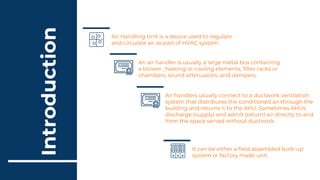
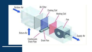
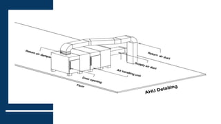
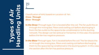
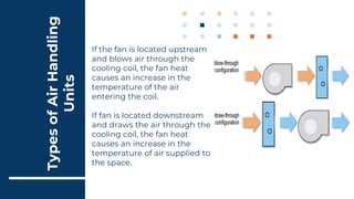
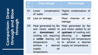
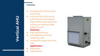
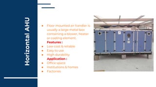
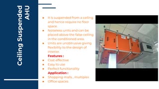
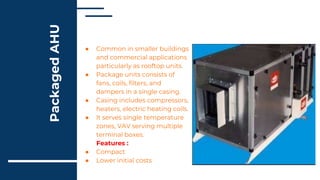
Air
Handling
Units
Basics -
GLOBAL HVAC CONSULTANTS
Air
Handling
Units
Basics -
GLOBAL HVAC CONSULTANTS
Content
• Introduction
• Construction and Materials
• Components of AHU
• Classification of AHU – Based on
location of fan
• Classification of AHU – Based on
Installation.
• Package AHU
• Installation Process
Introduction
Air handlers usually connect to a ductwork ventilation
system that distributes the conditioned air through the
building and returns it to the AHU. Sometimes AHUs
discharge (supply) and admit (return) air directly to and
from the space served without ductwork.
It can be either a field assembled built-up
system or factory made unit.
Air Handling Unit is a device used to regulate
and circulate air as part of HVAC system.
An air handler is usually a large metal box containing
a blower , heating or cooling elements, filter racks or
chambers, sound attenuators, and dampers.
Material of Insulation :
Polyethylene foam
Casing : Double skin
or Single skin
Panels and frames :
They are internally
bolted fixings to avoid
welding.
Material of casing :
GI/MS powder coated.
Construction
and
Materials
Drain pan : 20G thick
sheet with
sandwiched
insulation of 25mm.
Type of construction :
Modular
Rubber caps: For
screws protruding
inside the units.
Sealing : Non –
hygroscopic gasket
compressed between
frame and panels.
Access panels with
hinged doors : For
servicing and
maintenance.
Fan and motor assembly :
Common frame isolated from
the unit by vibration isolators
Components
● Return Air Opening with Volume
Control Damper : The opening which
receive the return air from the
building and volume damper controls
the amount of airflow.
● Mixing box : The return air and fresh
air are mixed inside it with the
required percentage.
● Fresh Air Opening : The opening for
fresh air and should have sand trap
louver with volume control damper
and filter.
● Pre- filter : First filter that return air
pass on it. Air purification from
impurities. Can be easily removed and
cleaned.
● Bag filter : It is the second stage of air
cleaning. After mixing box, air passes
on to bag filter.
Components
● Cooling coil : Cold water passes
through cooling coil. Hot return air
passes on the coil. Heat exchange
takes place between the two. The air
becomes cold and send to room. Coils
are made up of Aluminum fins which
are bonded to copper tubes.
● Electrical Heater : Optional if we need
heating.
● Fan section : Fan can be DIDW
Centrifugal forward curved or
backward curved fans. It is provide
with an electric motor.
● Drain pan : It is used to collect
condensate water from cooling coil.
The galvanized drain pan is light gray
powder-painted for corrosion
protection.
Types
of
Air
Handling
Units
Classification of AHU based on Location of fan.
Draw- Through
Blow- Through
In the Draw-Through type, Fan is located after the coil. The fan pulls the air
through the mixing box, filters and cooling coil before discharging it
from the fan outlet to the space to be conditioned or to the ducting
network. The design can be vertical or horizontal. In this case, the section
before the fan has negative pressure.
In the Blow-Through type, Fan is located before the coil. The fan blows the
air through the mixing box, filters and cooling coil before discharging
them to the space being conditioned or the ducting system. In this case,
the section after the fan has positive pressure.
Types
of
Air
Handling
Units
If the fan is located upstream
and blows air through the
cooling coil, the fan heat
causes an increase in the
temperature of the air
entering the coil.
If fan is located downstream
and draws the air through the
cooling coil, the fan heat
causes an increase in the
temperature of air supplied to
the space.
Comparison-
Draw
through
and
Blow
through
Sl
No.
Draw through Blow through
01 Lower condensation
of water.
Higher condensation of
water.
02 Less air leakage. More chances of air
leakage.
03 Heat generated by fan
and motor added to
air downstream of
cooling coil, requiring
a colder leaving coil
temperature to
achieve a desired
supply air
temperature.
Heat generated by fan
and motor added to air
upstream of cooling coil,
allowing a warmer
leaving coil temperature
to achieve a desired
supply air temperature.
Vertical AHU
Types
of
Air
Handling
Units
Horizontal AHU Ceiling suspended
AHU
Vertical
AHU
● Designed for vertical room
mounting.
● It comes with a fan and a
cabinet that can produce
high profile static pressures
without occupying larger
footprint area.
Features :
● High performance
● Cost effective small air
handling units
● Suitable for space with less
area.
Application :
● Classroom
● Laboratories
Horizontal
AHU ● Floor mounted air handler is
usually a large metal box
containing a blower, heater
or cooling element.
Features :
● Low cost & reliable
● Easy to use
● High durability
Application :
● Office space
● Institutions & homes
● Factories
Ceiling
Suspended
AHU
● It is suspended from a ceiling
and hence require no floor
space.
● Noiseless units and can be
placed above the false ceiling
in the conditioned area.
● Units are unobtrusive giving
flexibility to the design of
interior.
Features :
● Cost effective
● Easy to use
● Perfect functionality
Application :
● Shopping malls , multiplex
● Office spaces
Packaged
AHU
● Common in smaller buildings
and commercial applications
particularly as rooftop units.
● Package units consists of
fans, coils, filters, and
dampers in a single casing.
● Casing includes compressors,
heaters, electric heating coils.
● It serves single temperature
zones, VAV serving multiple
terminal boxes.
Features :
● Compact
● Lower initial costs
Advantages
&
Disadvantages
–
Package
AHU
Sl
No.
Advantages Disadvantages
01 Modular construction and
wide selection of unit sizes.
AHU is physically large and
requires careful planning in
terms of location.
02 Low energy consumption Careful coordination required
with builders with regards
with other services.
03 Low risk of condensation :
Air tight
Sophisticated duct work and
controls.
04 Easy installation and
maintenance.
Zone heaters may have to be
incorporated into duct
branches.
Installation
Process
● Lifting or rigging the ahu to site.
● Locate the ahu in the ahu room.
● Preparing the unit for installation.
● Assembling the unit.
● Cabinet installation.
● Fan installation.
● Electrical installation.
● Coil and piping installation sheet.
● Metal installation.
● Final installation and control installation.
● Final sensor and actuator calibration verification.
Thank You

air handling unit

  • 1.
  • 2.
  • 3.
    Content • Introduction • Constructionand Materials • Components of AHU • Classification of AHU – Based on location of fan • Classification of AHU – Based on Installation. • Package AHU • Installation Process
  • 4.
    Introduction Air handlers usuallyconnect to a ductwork ventilation system that distributes the conditioned air through the building and returns it to the AHU. Sometimes AHUs discharge (supply) and admit (return) air directly to and from the space served without ductwork. It can be either a field assembled built-up system or factory made unit. Air Handling Unit is a device used to regulate and circulate air as part of HVAC system. An air handler is usually a large metal box containing a blower , heating or cooling elements, filter racks or chambers, sound attenuators, and dampers.
  • 5.
    Material of Insulation: Polyethylene foam Casing : Double skin or Single skin Panels and frames : They are internally bolted fixings to avoid welding. Material of casing : GI/MS powder coated. Construction and Materials Drain pan : 20G thick sheet with sandwiched insulation of 25mm. Type of construction : Modular Rubber caps: For screws protruding inside the units. Sealing : Non – hygroscopic gasket compressed between frame and panels. Access panels with hinged doors : For servicing and maintenance. Fan and motor assembly : Common frame isolated from the unit by vibration isolators
  • 7.
    Components ● Return AirOpening with Volume Control Damper : The opening which receive the return air from the building and volume damper controls the amount of airflow. ● Mixing box : The return air and fresh air are mixed inside it with the required percentage. ● Fresh Air Opening : The opening for fresh air and should have sand trap louver with volume control damper and filter. ● Pre- filter : First filter that return air pass on it. Air purification from impurities. Can be easily removed and cleaned. ● Bag filter : It is the second stage of air cleaning. After mixing box, air passes on to bag filter.
  • 8.
    Components ● Cooling coil: Cold water passes through cooling coil. Hot return air passes on the coil. Heat exchange takes place between the two. The air becomes cold and send to room. Coils are made up of Aluminum fins which are bonded to copper tubes. ● Electrical Heater : Optional if we need heating. ● Fan section : Fan can be DIDW Centrifugal forward curved or backward curved fans. It is provide with an electric motor. ● Drain pan : It is used to collect condensate water from cooling coil. The galvanized drain pan is light gray powder-painted for corrosion protection.
  • 11.
    Types of Air Handling Units Classification of AHUbased on Location of fan. Draw- Through Blow- Through In the Draw-Through type, Fan is located after the coil. The fan pulls the air through the mixing box, filters and cooling coil before discharging it from the fan outlet to the space to be conditioned or to the ducting network. The design can be vertical or horizontal. In this case, the section before the fan has negative pressure. In the Blow-Through type, Fan is located before the coil. The fan blows the air through the mixing box, filters and cooling coil before discharging them to the space being conditioned or the ducting system. In this case, the section after the fan has positive pressure.
  • 12.
    Types of Air Handling Units If the fanis located upstream and blows air through the cooling coil, the fan heat causes an increase in the temperature of the air entering the coil. If fan is located downstream and draws the air through the cooling coil, the fan heat causes an increase in the temperature of air supplied to the space.
  • 13.
    Comparison- Draw through and Blow through Sl No. Draw through Blowthrough 01 Lower condensation of water. Higher condensation of water. 02 Less air leakage. More chances of air leakage. 03 Heat generated by fan and motor added to air downstream of cooling coil, requiring a colder leaving coil temperature to achieve a desired supply air temperature. Heat generated by fan and motor added to air upstream of cooling coil, allowing a warmer leaving coil temperature to achieve a desired supply air temperature.
  • 14.
  • 15.
    Vertical AHU ● Designed forvertical room mounting. ● It comes with a fan and a cabinet that can produce high profile static pressures without occupying larger footprint area. Features : ● High performance ● Cost effective small air handling units ● Suitable for space with less area. Application : ● Classroom ● Laboratories
  • 16.
    Horizontal AHU ● Floormounted air handler is usually a large metal box containing a blower, heater or cooling element. Features : ● Low cost & reliable ● Easy to use ● High durability Application : ● Office space ● Institutions & homes ● Factories
  • 17.
    Ceiling Suspended AHU ● It issuspended from a ceiling and hence require no floor space. ● Noiseless units and can be placed above the false ceiling in the conditioned area. ● Units are unobtrusive giving flexibility to the design of interior. Features : ● Cost effective ● Easy to use ● Perfect functionality Application : ● Shopping malls , multiplex ● Office spaces
  • 18.
    Packaged AHU ● Common insmaller buildings and commercial applications particularly as rooftop units. ● Package units consists of fans, coils, filters, and dampers in a single casing. ● Casing includes compressors, heaters, electric heating coils. ● It serves single temperature zones, VAV serving multiple terminal boxes. Features : ● Compact ● Lower initial costs
  • 19.
    Advantages & Disadvantages – Package AHU Sl No. Advantages Disadvantages 01 Modularconstruction and wide selection of unit sizes. AHU is physically large and requires careful planning in terms of location. 02 Low energy consumption Careful coordination required with builders with regards with other services. 03 Low risk of condensation : Air tight Sophisticated duct work and controls. 04 Easy installation and maintenance. Zone heaters may have to be incorporated into duct branches.
  • 20.
    Installation Process ● Lifting orrigging the ahu to site. ● Locate the ahu in the ahu room. ● Preparing the unit for installation. ● Assembling the unit. ● Cabinet installation. ● Fan installation. ● Electrical installation. ● Coil and piping installation sheet. ● Metal installation. ● Final installation and control installation. ● Final sensor and actuator calibration verification.
  • 21.