Downloaded 181 times


![CHAPTER ONE
1. INTRODUCTION
1.1 Background of screw car jack
Screw type mechanical jacks were very common for jeeps and trucks of World War II vintage.
For example, the World War II jeeps (Wally’s MB and Ford GPW) were issued the "Jack,
Automobile, Screw type, Capacity 1 1/2 ton", Ordnance part number 41-J-66. This jacks,
and similar jacks for trucks, were activated by using the lug wrench as a handle for the jack's
ratchet action to of the jack. The 41-J-66 jack was carried in the jeep's tool compartment. Screw
type jack's continued in use for small capacity requirements due to low cost of production raise
or lower it. Before the invention of weight lifting device such as screw jack, hydraulic jack,
crane, etc., the early man apply a crude way of lifting objects to great heights through the use of
ropes and rollers, which was mostly applied in the construction area, where, it was used to raise
mortar (cement, sand & water). [1]
The virtues of using a screw as a machine, essentially an inclined plane wound round a cylinder,
was first demonstrated by Archimedes in 200BC with his device used for pumping water.
There is evidence of the use of screws in the Ancient Roman world but it was the great
Leonardo da Vinci, in the late 1400s, who first demonstrated the use of a screw jack for lifting
loads. Leonardo’s design used a threaded worm gear, supported on bearings, that rotated by
the turning of a worm shaft to drive a lifting screw to move the load - instantly recognizable as
the principle we use today. We can’t be sure of the intended application of his invention, but
it seems to have been relegated to the history books, along with the helicopter and tank, for
3 almost four centuries.
It is not until the late 1800s that we have evidence of the product being developed further. With
the industrial revolution of the late 18th and 19th centuries came the first use of screws in
machine tools, via English inventors such as John Wilkinson and Henry Causley The most
notable inventor in mechanical engineering from the early 1800s was undoubtedly the
mechanical genius Joseph Whitworth, who recognized the need for precision had become as
important in industry as the provision of power .A screw jack that has a built-in motor is now
referred to as a linear actuator but is essentially still a screw jack.
Today, screw jacks can be linked mechanically or electronically and with the advances in
motion-control, loads can be positioned to within microns. Improvements in gear technology
together with the addition of precision ball screws and roller screws mean the applications for
screw jacks today are endless and a real alternative to hydraulics in terms of duty cycles and
speed at a time when industry demands cleaner, quieter and more reliable solutions. Car jacks
usually use mechanical advantage to allow a human to lift a vehicle by manual force alone. The
use of screws in the Ancient Roman world but it was the great Leonardo Vinci, in the late 1400s,
who first demonstrated the use of a screw jack for lifting loads. Leonardo’s design used threaded](https://image.slidesharecdn.com/screwjackproject1byebrahim-190421094226/85/Screw-jack-project_1-12-320.jpg)
![worm gear, supported on bearings, that rotated by the turning of a worm shaft to drive a lifting
screw to move the load - instantly recognizable as the principle we use today [2]
1.1.1 Types of jacks
Jacks are of mainly two types- mechanical and hydraulic. They vary in size depending
on the load that they are used to lift
1.1.1.1 Mechanical Jacks
A mechanical jack is a device which lifts heavy equipment. The most common form
is a car jack, floor jack or garage jack which lifts vehicles so that maintenance can be
performed. Car jacks usually use mechanical advantage to allow a human to lift a vehicle
by manual force alone. More powerful jacks use hydraulic power to provide more lift over
greater distances. Mechanical jacks are usually rated for maximum lifting capacity. There
are several types of mechanical jacks: scissor jack, floor jack, scaffolds, bottle jack etc.
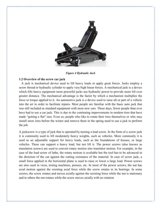
Scissor Jacks
Scissors jacks are also mechanical and have been in use at least since the 1930s. A scissor jack
is a device constructed with a cross-hatch mechanism, much like a scissor, to lift up a vehicle
for repair or storage. It typically works in just a vertical manner. The jack opens and folds
closed, applying pressure to the bottom supports along the crossed pattern to move the lift
Figure 1Scissor Jack
House jack
A house jack, also called a screw jack, is a mechanical device primarily used to lift
buildings from their foundations for repairs or relocation. A series of jacks is used and then
wood cribbing temporarily supports the structure. This process is repeated until the desired
height is reached. The house jack can be used for jacking carrying beams that have settled or
for installing new structural beams.](https://image.slidesharecdn.com/screwjackproject1byebrahim-190421094226/85/Screw-jack-project_1-13-320.jpg)


![CHAPTER TWO
LITRATURE REVIEW
2.1 Introduction to literature reviews about design of screw car jack
In this section project papers are discussed related to the present work. Published
papers are highlight in this section. The main purpose of this literature review is to get
information about the project from the reference books, magazines, journals, technical papers
and web sites. In this chapter the discussion will be made base on all the sources. After going
through various literatures on pressure vessel supports some of the selected papers are cited
below and which are considered as basis for developing structural analysis methodology for
screw car jack.
2.2 Illustrations of literature reviews about design of screw jacks
“Experimental Investigation of the Performance of a Laboratory Screw Jack’ and concluded it
has been established that the relationship between the load and efficiency, and between the load
and effort applied is linear and was also discovered that decrease in load means decrease in effort
and decrease in load causes increase in efficiency [3]
In this paper a lifting device is a system that allows small force (effort) to overcome a large
force or load. There are practically hundreds of uses for lift tables in manufacturing, warehousing
and distribution facilities. The addition of this device (lift table) makes job faster, safer and
easier. Some typical applications include; machine feeding and off-loading, product assembly,
inspection quality control repair, feeding and offloading conveyor levels. The commonest
method for operating a scissors lift is the use of a power screw [4]
The manually operated screw jack lift is a device that makes use of a horizontally placed power
screw to overcome large load through less effort applied on the power screw. One of the most
important factors of lift platform is its stability. Knowing that stability is a source of concern for
a lift platform, its positioning should be on a flat surface and the load should be place or
concentrated at the center of gravity of the table. Other constraint to be considered is the
deflection of the unit. Deflection in the lift can be defined as the resulting change in elevation of
all parts of a screw jack lift assembly, typically measured from the floor to the top of the
platform deck, whenever load is applied to or removed from the lift. [5]
Safety requirement for industrial scissor lifts states that “All industrial screw jack lift will deflect
under load”. The Shop standard goes on to outline the maximum allowable deflection base on
platform size and number of scissor mechanism within the lift design. Screw jack lift deflection
becomes more critical in material handling applications where the lift must interface with
adjoining, fixed elevations, especially when transferring rolling load.
In these cases, it is important that any difference in elevation between adjoining surfaces during
material transfer be minimize or if not totally eliminated. Before attempting to discuss how to](https://image.slidesharecdn.com/screwjackproject1byebrahim-190421094226/85/Screw-jack-project_1-19-320.jpg)
![limit scissor lift deflection, it is important to understand the contributing factors to a lift total
deflection. An open or raised scissor acts very much like a spring would apply a load and it
compresses, remove a load and it expands. Such component within the screw jack lift has the
potential to store or release energy when loaded and unloaded (and therefore deflects).
There are application specific characteristics that may promote deflection, understanding these
root causes helps to pin-point and apply effective measures to limit them. Leg deflection due to
bending is as a result of stress which is driven by the total weight supported by the legs, scissor
leg length, and available leg cross section. The longer the scissors leg length, the more difficult it
is to control the bending under load other important component is the platform structure.
Platform bending will increase as the load center of gravity move away from the center
(unevenly distributed load) or at an edge (eccentric loading) of the platform. Also as the scissor
open during rising of the lift, the rollers could roll back towards the platform hinges and create
an increasingly unsupported overhung portion of the platform assembly. Increase platform
strength via increase support structure material height does improve resistance to deflection, but
also contributes to an increase collapsed height of the lift. The lift base frame is usually placed
on the floor and may not experience deflection. For cases where the scissor lift is mounted to an
elevated or portable frame, the potential for deflection increases. To effectively resist deflection,
the base frame must be rigidly supported from beneath to support the point loading created by
the two scissor leg hinges. [6]](https://image.slidesharecdn.com/screwjackproject1byebrahim-190421094226/85/Screw-jack-project_1-20-320.jpg)


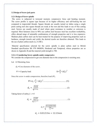
![For square threads of fine series, the following dimensions of screw are selected from Appendix
D (Gupta, 2005) hence,
The core diameter =12mm, =14mm and pitch p=l=2mm
Figure 6 section of screw spindle
3.2.1.2 Considering torsional shear stress for screw spindle
We know that torque required to rotate the screw is the same torque required to lift the load
which is given by;
T1= P× =
[ ( )]
………………………..…... (4)
We know that =
( )
=
( )
= 13mm
And
tan = = = 0.04897 α=tan =2.8
Assuming coefficient of friction between screw and nut,
μ=tan =0.1 β=tan =5.71
A screw will be self-locking if the friction angle is greater than helix angle or coefficient of
friction is greater than tangent of helix angle i.e. μor tan >tan
The torque required to raise a load by means of square threaded screw may be determined by
considering a screw jack as shown in Figure below, the load to be raised or lowered is placed
on the head of the square threaded rod which is rotated by the application of an effort at the
end of lever for lifting or lowering the load.](https://image.slidesharecdn.com/screwjackproject1byebrahim-190421094226/85/Screw-jack-project_1-29-320.jpg)

![∴ Torque required to rotate the screw in the nut, we know that torque required to rotate the screw
is the same torque required to lift the load which is given by;
T1 = P× = w×tan( ) = w×* +× ……………..…... (5)
T1=
[ ( )]
= 15.72Nm
Now compressive stress due to axial load,
= =
( )
………………………………..…... (6)
=
( )
Since the screw is subjected to a twisting moment, therefore torsional shear stress is induced.
This is obtained by considering the minimum cross-section of the screw. We know that Shear
stress due to torque transmitted by the screw:
τ ( )
…………………………………..…... (7)
τ ( )
3.2.1.3 Considering Maximum principal stress
∴Maximum principal stress (tensile or compressive),
( )= ×[ √( ) ]…………………………………..…... (8)
( )= ×[ √( ) ( ) ]
( )
The design value of = = 140MPa
3.2.1.4 Considering maximum shear stress
When the screw is subjected to both direct stress and torsional shear stress, then the design
must be based on maximum shear stress theory, according to which maximum shear stress on
the minor diameter section.](https://image.slidesharecdn.com/screwjackproject1byebrahim-190421094226/85/Screw-jack-project_1-31-320.jpg)
![= ×√( ) …………………………………..…... (9)
×√( ) ( )
= 85.25Mpa
The design value of τ = = 90Mpa
Check: These maximum shear and compressive stresses are less than the permissible stresses;
hence the spindle or shaft is safe
3.2.2 Design of nut
There exists a relative motion between the screw and the nut which causes friction, friction in
turn causes wear of the material used for screw and nut. Therefore, it requires one of the two
members to be softer. A suitable material for the nut is therefore phosphor bronze which is a
copper alloy with small percentage of lead and has the following advantages;
Good corrosion resistance
Low coefficient of friction.
High tensile strength.
From 6.3 Appendixes C: Safe Bearing Pressure for Power Screws [ ]
Type of power
Screw
Screw material Nut material Bearing
pressure
Rubbing speed
Screw jack Steel Bronze 11−17Mpa 3m/s
Table 7 Safe bearing pressures for power screws
3.2.2.1 Considering Height of the Nut
The screw and nut are in match there is a chance of rubbing due to there is an area which resists.
Resists area (A) = A = ×( − )
A= ( − )
A=40.84mm2
Let n= Number of threads in contact with the screwed spindle,](https://image.slidesharecdn.com/screwjackproject1byebrahim-190421094226/85/Screw-jack-project_1-32-320.jpg)
![h = Height of nut = n × p
t = Thickness of screw = =
Assume that the load is distributed uniformly over the cross-sectional area of nut.
In order to reduce wear of the screw and nut, the bearing pressure on the thread surfaces must
be within limits. In the design of power screws, the bearing pressure depends upon the materials
of the screw and nut, relative velocity between the nut and screw and the nature of lubrication.
Assuming that the load is uniformly distributed over the threads in contact, the bearing pressure
∴ bearing strength of nut
W = A × n × → n =
Material specification for the nut is phosphor bronze which has tensile stress = 150MPa,
compressive stress = 125MPa, shear stress = 105MPa, safe bearing pressure not exceed 17MPa
and a coefficient of friction of 0.12 Assuming the load is uniformly distributed over the entire
cross section of the nut and substituting for the known values we get the number of threads in
contact,
[( ) ( )]
…………………………………..…... (10)
17×
[[ ) ( )]]
17×
n=23.1 say n=23 threads
So we can find the height of the nut
=n × p
=23 × 2=46mm
Check: For a safe nut height ≤ 4 =48mm (Gupta, 2005)](https://image.slidesharecdn.com/screwjackproject1byebrahim-190421094226/85/Screw-jack-project_1-33-320.jpg)
![3.2.2.2 Stresses in the Screw and Nut
Now, let us check the stresses induced in the screw and nut. The threads of the screw at the
core or root diameter and the threads of the nut at the major diameter may shear due to the axial
load. Assuming that the load is uniformly distributed over the threads in contact,
Shear stress in the screw is as follows;
( )= …………………………………..…... (11)
( )
Shear stress in the nut is as follows;
( )= …………………………………..…... (12)
( )
The given value of
Since these stresses are within permissible limit, therefore design for nut is safe.
3.2.2.3 The outer diameter of Nut
Let
Outer diameter of nut,
Outside diameter for nut collar, and
= Thickness of nut collar.
Outer diameter is found by considering the tearing strength of the nut.
[( ) ( )]
…………………………………..…... (13)
Where tearing strength of the nut = tensile stress
Then we get as follows;](https://image.slidesharecdn.com/screwjackproject1byebrahim-190421094226/85/Screw-jack-project_1-34-320.jpg)
![[( ) − ( )]
3.2.2.4The outside diameter of Collar
Outside diameter is found by considering the crushing strength of the nut collar.
[( ) ( )]
…………………………………..…... (14)
Where crushing strength of the nut = compressive stress
Then we get as follows;
[( ) − ( )]
Figure 9 section of nut collar 1
3.2.2.5 Thickness of the Nut Collar](https://image.slidesharecdn.com/screwjackproject1byebrahim-190421094226/85/Screw-jack-project_1-35-320.jpg)
![The thickness of nut collar is found by considering the shearing strength of the nut collar
w = 𝛑× × ×𝛕
…………………………………..…... (15)
Shearing strength of nut collar =
Therefore
3.2.3 Design for Head and Cup
3.2.3.1 Dimensions of Diameter of Head on Top of Screw and for the Cup
Assuming
mm mm
The head is provided with two holes at the right angles to receive the handle for rotating the
screw. The seat for the cup is made equal to the diameter of head, i.e. 25mm and it is given
chamfer at the top. The cup prevents the load from rotating. The cup is fitted to the head with
a pin of diameter approximately [ ]
The pin should remain loose fit in the cup.
Figure 10 section of pin](https://image.slidesharecdn.com/screwjackproject1byebrahim-190421094226/85/Screw-jack-project_1-36-320.jpg)
![Take length of pin to be 4mm.
Other dimensions for the cup may be taken as follows:
Height of cup = 35mm
Thickness of cup = 10mm
Fillet radii = 5mm
Diameter at the top of the cup = Diameter of the head = 80mm
Figure 11 section of cup
3.2.3.2 Torque Required to Overcome Friction
We know that by assuming uniform pressure condition torque required to overcome friction is
given as follows;
*
( ) ( )
( ) ( )
+…………………………………..…... (16)
Where
Diameter of head = 25mm
Diameter of pin = 6mm
Substituting for the known values we get;
[
( ) − ( )
( ) − ( )
]
3.2.3.3 Total Torque Subjected to the Handle
Total torque to which the handle is subjected is given by
+](https://image.slidesharecdn.com/screwjackproject1byebrahim-190421094226/85/Screw-jack-project_1-37-320.jpg)
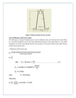
![Activity Professional use Domestic use
Pushing 200N( ) 119N( )
Pushing 145N( ) 96N( )
Table 8 Maximal Isometric Force by General European Working Population for Whole Body Work in a Standing
Posture
Therefore taking the force of 96N in domestic use [ ]then the length of the
handle required is
L =
L =
The length of the handle may be fixed by giving some allowance for gripping 70mm.
Therefore, the length of the handle/lever is 381mm.
Figure 12 section of lever
3.2.3.4 Diameter of Handle/Lever
A little consideration will show that an excessive force applied at the end of lever will cause
bending. Considering bending effect, the maximum bending moment on the handle,
M = force applied × length of lever
M = 96N×0.38m
M =36.48Nm
Let D= Diameter of the handle.
Assuming that the material of the handle is same as that of screw, therefore taking bending
stress
The diameter of the handle/lever may be obtained by considering bending effects. We know
that bending moment;](https://image.slidesharecdn.com/screwjackproject1byebrahim-190421094226/85/Screw-jack-project_1-38-320.jpg)

![3.2.3.6 Design Check against Instability/Buckling
We know that the effective length for the buckling of screw,
=
= + …………………………………..…... (19)
=265+
=273mm
When the axial load is compressive and the unsupported length of the screw between the load
and the nut is short. But when the screw is axially loaded in compression and the unsupported
length of the screw between the load and the nut is too great, and then the design must be based
on
column theory assuming suitable end conditions. When the screw reaches the maximum lift, it
can be regarded as strut whose lower end is fixed and the load end is free. Therefore, buckling
or critical load for this given condition. In such cases, the cross-sectional area corresponding
to core diameter may be obtained by using Rankin-Gordon formula or J.B. Johnson’s formula.
According to this,
[ − ( ) ]…………………………………..…... (20)
Where
Yield stress = = 385Mpa
C = End fixity coefficient. The screw is considered to be strut with lower end
fixed and load end free. Therefore C = 0.25
k = the radius of gyration = √ = 0.25 =0.003m
I = Moment of inertia of the cross section
The buckling load as obtained by the above expression and must be higher than the load at which
the screw is designed. Substituting for the known values:](https://image.slidesharecdn.com/screwjackproject1byebrahim-190421094226/85/Screw-jack-project_1-40-320.jpg)
![[ − ( ) ]
( ) [ − ( ) ]
70,327.77N
Where
W = 16,186.5N
, hence there is no chance for the screw to buckle.
3.2.4 Design of body
Most of the frames are in conical shape and hollow internally to accommodate both the nut and
screw assembly. The frame works to ensure that the screw jack is safe and has a complete rest on
the ground. The purpose of the frame is to support the screw jack and enable it to withstand
compressive load exerted on it.
The frame is a bit complex and thus requires casting as a manufacturing process. For this
reason, grey cast iron as a material is selected for the frame. This is also evident from the case
study on previous design of the same product. Cast iron is cheap and it can give any complex
shape without involving costly machining operations. Cast iron has higher compressive
strength compared to steel. Therefore, it is technically and economically advantageous to use
cast iron for the frame. Graphite flakes cast iron with an ultimate tensile strength of 220MPa is
considered suitable for the design of the frame. The graphite flakes improve the ability to resist
compressive load.
The dimension of the body may be fixed and given as in shown in the figure above
1. Diameter of the body at the top,
2. Thickness of the body,](https://image.slidesharecdn.com/screwjackproject1byebrahim-190421094226/85/Screw-jack-project_1-41-320.jpg)


![REFERENCE
1) Collection, J., 2015. hubpages.com › Autos › Automobile History. [Online] retrieved 10
June 2017 from https://www.history of screw jacks.com.
2) Gupta, R. K. &. J., 2005. Theory of Machines. Revised Edition ed. Punjab, India: S.
Chand and Company. Stephen Tambari , Petaba Lemii, Kanee Sorbari ,Nzidee lelesi,
“Experimental
3) Investigation of the Performance of a Laboratory Screw Jack”, IOSR Journal of
Mechanical and Civil Engineering (IOSR-JMCE), Volume 12, Issue 4.
4) J.J. Ferreira, M. B. M. G., 2004. Review of the risks associated with pushing and pulling
heavy loads. First ed. Sheffield: Health and safety Laboratory.
5) Michael-Adel, 2008 Material Selection for a Manual Winch Rope Drum. Volume 1.
6) ANSI MH29.1 screw jack Design for Use in the Automotive Industry New Jersey, 2004
7) Kempster, M. H. A., 1984. Engineering Design III. London: Hodder and Stoughton Ltd.
8) Nisbet, R. G. B. &. J. K., 2015. Shigley's Mechanical Engineering design. Tenth Ed. New
York: McGraw-Hill.
9) Prof. F.M. Oduori, E. D. O., 2016. Material Selection for a Manual Winch Rope Drum.
Volume 1.
10) Bhandari, V. B., 2010. Design of Machine Elements. Third Edition Ed. New Delhi: Tata
McGraw-Hill Education.
11) Ashby, M. F., 2005. Material Selection in Mechanical Design. 3rd Ed. New York:
Pergamum Press
12) Fasteners, C. o., 2005. Technical Reference Guide. Ninth Edition ed. Winona, Minnesota:
Fastenal Industrial & Construction Supplies.
13) Marshek, R. C. J. &. K. M. Fundamental of Machine Design Components. Fifth Edition.](https://image.slidesharecdn.com/screwjackproject1byebrahim-190421094226/85/Screw-jack-project_1-61-320.jpg)


The document provides details about the design of a screw jack. It includes an introduction that discusses the background and history of screw jacks. It then outlines the objectives, scope, limitations and methodology of the screw jack design project. The document is divided into multiple chapters that cover literature reviews, detailed design and analysis of the screw jack parts, results and discussion, conclusions, and part/assembly drawings. The design aims to develop a screw jack that can lift a maximum load of 1.65 tons and optimize the existing design by replacing the hand lifter with a pedal lever to reduce energy usage.


![Final report[1]](https://cdn.slidesharecdn.com/ss_thumbnails/finalreport1-170515065010-thumbnail.jpg?width=640&height=640&fit=bounds)


