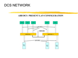
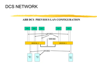
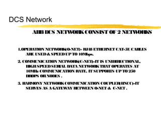
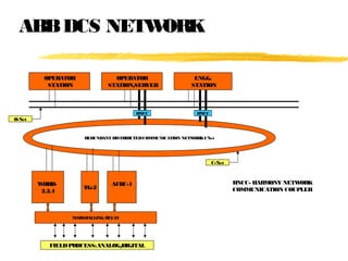
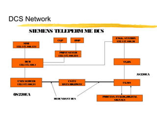
DCS Networks
PRESENTATION BY: ASHISHPATIL
POWERPLANT,
MONNET ISPAT & ENERGY LTD
MANDIRHASAUD,RAIPUR.
PROJECT OFFICE
TIME: 04:00 PM; DATE:DECEMBER15, 2012
INDEX
A) BASICS OF NETWORKING
1 HOW NETWORKING STARTED
2 WHAT IS NETWORKING
3 TYPES OF NETWORK & DIFFERENT TOPOLOGIES
4 WHAT IS OSI LAYER & ITS FUNCTION
5 IP ADDRESSING
B) DCS NETWORKS
1 ABB SYMPHONY HARMONY DCS NETWORK
2 SIEMENS TELEPERM ME DCS NETWORK
Basics of Networking
Networking began its infancy in the mid -1960’s.
by the US Department of Defence (DoD).
The original intention of networking was being
developed to withstand a nuclear war.
Telephone networks were to vulnerable and would
terminate all conversations should a nuclear war
occur.
ARPA (Advanced Research Projects Agency)
was created in response with the launching of the
Sputnik in 1957.
ARPA decided that a DoD network should be packet-
switched networked consisting of a subnet and
host computers.
Experimental network research was awarded to
UCLA, UCSB, SRI and Univ. of Utha in 1969. These
areas were because they all had a large number
of ARPA contracts.
Basics of Networking
These 4 universities also had different and completely
incompatible host computers.
ARPANET protocols were not suitable for running over
multiple networks, so TCP/IP model and protocols
were invented in 1974.
ARPA awarded several other contracts and specifically
Univ.. of California at Berkeley to integrate the
protocols with the Berkeley UNIX.
Basics of Networking
Berkeley developed a convenient program interface
to the network and wrote many applications, utility,
and management programs to make networking easier.
In it early infancy, the OSI protocols were crushed and
the TCP/IP protocols were already in widespread use.
The OSI Model had seven layers because at the time,
IBM had a propriety seven -layer protocol called
SNA (Systems Network Architecture).
Basics of Networking
At the time, IBM dominated the computer companies
and every was scared to death that IBM would use
its clout to force everyone to use SNA.
The OSI was to be produced like an IBM-reference
model.
The OSI model became the world standard and was
not controlled by one company, but by a neutral
organization, ISO (International Standards Association).
Basics of Networking
NETWORKING IS THE SHARING OF
INFORMATION & SERVICES.
COMPUTER NETWORKING PROVIDES
THE COMMUNICATION TOOLS TO
ALLOW COMPUTERS TO SHARE
INFORMATION & ABILITIES
TYPES OF NETWORKS
LAN – LOCAL AREA NETWORK IS A SMALL
GEOGRAPHICAL AREA SUCH AS OUR SCHOOL
BOARD.
MAN – METROPOLITAN AREA NETWORK IS A
NETWORK OVER A LARGER GEOGRAPHICAL AREA
SUCH AS THE PROVINCIAL GOVERNMENT.
WAN – WIDE AREA NETWORK IS A NETWORK USED
OVER AN EXTREMELY LARGE GEOGRAPHICAL AREA
SUCH AS THE FEDERAL GOVERNMENT.
Basics of Networking
NETWORKS ARE BROKEN INTO 3 TOPOLOGIES.
THEY ARE:
•BUS TOPOLOGY
•STAR TOPOLOGY
•RING TOPOLOGY
Basics of Networking
BUS TOPOLOGY ALLOWS INFORMATION TO BE
DIRECTED FROM ONE COMPUTER TO THE OTHER.
LOTS OF BINARY COLLISION THOUGH.
Basics of Networking
STAR TOPOLOGY IS THE MOST COMMON TYPE
USED. ALL COMPUTERS ARE ATTACHED TO A HUB.
LESS COLLISIONS AND MOST EFFICIENT.
Basics of Networking
RING TOPOLOGY- USES A TOKEN TO PASS
INFORMATION FROM 1 COMPUTER TO THE OTHER.
A TOKEN IS ATTACHED TO THE MESSAGE BY THE
SENDER TO IDENTIFY WHICH COMPUTER SHOULD
RECEIVE THE MESSAGE. AS THE MESSAGE MOVES
AROUND THE RING, EACH COMPUTER EXAMINES
THE TOKEN. IF THE COMPUTER IDENTIFIES THE TOKEN
AS ITS OWN, THEN IT WILL PROCESS THE
INFORMATION.
Basics of Networking
A DISADVANTAGE OF A TOKEN RING IS IF ONE
COMPUTER IS BROKEN OR DOWN, THE MESSAGE
CANNOT BE PASSED TO THE OTHER COMPUTERS.
Basics of Networking
The seven layers of the OSI Model are:
Layer 1 PHYSICAL
Layer 2 DATA-LINK
Layer 3 NETWORK
Layer 4 TRANSPORT
Layer 5 SESSION
Layer 6 PRESENTATION
Layer 7 APPLICATION
Basics of Networking
THE PHYSICAL LAYER
The physical layeris concerned with transmitting
raw bits overa communication channel though
hubs, wires (cat5UTP), modems, networkcards…
basically anything that is physical to the network.
When looking at network cables, there are
2 types that affect nodes. They are:
In networking, computers are also known as
Hosts or Nodes.
Basics of Networking
•Straight through cables oralso known as patch cables
•Cross-overcables
The difference in the cables are the way the wires
are connected within the RJ45. I have attached a
sheet foryou in yourpackage.
Basics of Networking
Wiring:
1-3 White/Orange
2-6 Orange
3-1 White/Green
6-2 Green
4-4 Blue
5-5 White/Blue
7-7 White/Brown
8-8 Brown
Typical CrossoverCable
Basics of Networking
TWISTED SHIELDED PAIR – USED IN PHONE LINES, NETWORKS
UNSHIELDED TWISTED PAIR “ “ “ “
COAXIAL CABLE – USED IN CABLEVISION GREAT FOR VIDEO
FIBRE OPTIC CABLES - USES LIGHT TO CARRY SIGNAL BUT
HARD TO WORK WITH AND LOOSES SIGNAL OVER LONGER
DISTANCES( 2 TO 25 KM)
COMMUNICATION CHANNELS
Basics of Networking
Crimping Tool Hub
Basics of Networking
THE DATA-LINKLAYER
The data link layer takes raw transmission and
transform it into a line that appears free of
transmission errors in the network layer.
The Data-LinkLayeralso is where you would find
the MAC Address. (Media Access Control). To find the
MAC Address of yourcomputer, orany computer:
Start/Programs/MS Prompt and type: ipconfig/all
Basics of Networking
"C:WINDOWS>" prompt, type "tracert
www.howstuffworks.com"
THE DATA-LINKLAYER
You will also find smart devices such as switches in
the Data-LinkLayer.
The digital information that needs to be sent such as
and e-mail, attachments, etc needs to be broken into
smallerbits known as packets.
These packets require some information similarto
sending a letterin the mail.
Basics of Networking
Hea der Tra iler (Footer)
Conta ins : Conta ins :
Ma c Address (if a va ila ble) Ma c Address (from your computer)
IP Address (where it's going) IP Address (where it ca me from)
PACKETS
Bits of
informa tion
THERE ARE A NUMBEROF PACKETS THAT WILL
FOLLOWEACHOTHERTOTHE FINAL DESTINATION.
Basics of Networking
THE NETWORKLAYER
The network layer is concerned with controlling
the operation of the subnet. A ROUTER is used to
determining how packets are routed from source
to destination.
If one path is busy, then the routerwill select another
path forthe packets to travel. So really, the packets
can all have different paths and find theirway to the
final destination.
Basics of Networking
THE NETWORKLAYER
The routerhas millions of IPaddressing built into
the software, and knows where to send the packets.
IPstands forInternet Protocol and is basically an
address that the packets will be sent to.
An example would be 216.27.61.137
Basics of Networking
THE NETWORKLAYER
If you lookat the IPAddress, the numberare broken
into different categories.
216. 27.61.137
Classification Hosts
216. 27.61.137
Octets
Basics of Networking
Classifications can be broken into 3 classes. They are:
Class A - Only the first octet is used foraddressing and
the balance used forhosts.
Class B- The first two octet are used foraddressing
and the balance used forhosts.
Class C - The first three octet are used foraddressing
and the balance used forhosts.
Basics of Networking
Every machine on the Internet has a unique
identifying number, called an IP Address.
A typical IP address looks like this:
216.27.61.137
But computers communicate in binary form.
Basics of Networking
The same IP address in binary:
11011000.00011011.00111101.10001001
216.27.61.137
Basics of Networking
If you add all the positions together, you get 32,
which is why IP addresses are considered
32-bit numbers
Combine the four octets and you get 232
or a possible
4,294,967,296 unique values.
11011000.00011011.00111101.10001001
Basics of Networking
Class A - This class is for very large networks,
such as a major international company might have.
IP addresses with a first octet from 1 to 126 are
part of this class.
Basics of Networking
CLASS A (Private IP)
FROM10.0.0.0 THROUGH10.255.255.255
CLASS A (Public IP)
FROM1.0.0.0 THROUGH126.0.0.0
Class B- This class is used for medium-sized networks.
A good example is a large college campus.
IP addresses with a first octet from 128 to 191
are part of this class. Class B addresses also include
the second octet as part of the Net identifier.
Basics of Networking
CLASS B(Private IP)
FROM172.16.0.0 THROUGH172.31.255.255
CLASS B(Public IP)
FROM128.0.0.0 THROUGH191.0.0.0
Class C - Class C addresses are commonly used for
small to mid-size businesses. IP addresses
with a first octet from 192 to 223 are part of this
class. Class C addresses also include the second
and third octets as part of the Net identifier.
Basics of Networking
CLASS C (Private IP)
FROM192.168.0.0 THROUGH192.168.255.255
CLASS C (Public IP)
FROM192.0.0.0 THROUGH223.0.0.0
Loopback- The IP address 127.0.0.1 is used
as the loopback address. This means that it is
used by the host computer to send a message
back to itself.
Basics of Networking
LOOPBACK
CLASS D(MULTICAST)
FROM224.0.0.0 TO 239.0.0.0
CLASS E (FORRESEARCH)
FROM240.0.0.0 TO 255.0.0.0
THE TRANSPORT LAYER
The transport layer “DIRECTS PACKETS”, splits it up into
smaller units if need be, pass these to the network
and ensure that the pieces are travelling in an
orderly fashion.
A series of protocols are also established in this
layerto ensure properflow of the packets.
You can basically describe the Transport Layeras
a “TRAFFIC COP”.
Basics of Networking
THE SESSION LAYER
The session layer allows different machines to
establish sessions between themselves.
Once communications are established, encryption
then begins both parties.
Basics of Networking
THE PRESENTATION LAYER
The Presentation Layer’s job is managing data
structures and converting from the representation
used inside the computer to the network standard
representation an vice versa.
In Otherterms, the Presentation layerbasically
takes the packets and re-assembles them so you can
open the e-mail orthe attachment.
If any packets got lost along the way, orwere
damaged, then the Presentation layerwill send a
sign to the senderthat it requires the specific packet.
Basics of Networking
THE APPLICATION LAYER
The Application layer contains a variety of protocols
that are commonly required.
Another Application layer function is file transfer.
Different file systems have different file naming
conventions, different ways of representing text lines,
and so on.
Transferring a file between two different systems
requires handling and other incompatibilities.
Basics of Networking
FTP - File Tra nsfer Protocol
FTP provides a sta ndard system for sending
a nd receiving files over IP networks.
HTTP Protocol
Web browsers a nd servers use the Hypertext
Tra nsfer Protocol (HTTP) protocol to
communica te.
Electronic Ma il Protocols
Severa l network protocols were developed
specifica lly to support electronic ma il over the
Internet.
THE APPLICATION LAYER
Basics of Networking
SO AP - Simple O bject Access
Protocol
SO AP defines a sta nda rd wa y to encode objects
within network pa ckets using XML.
DHCP
The Dyna mic Host Configura tion Protocol
(DHCP) supports a utoma tic a ddress a ssignment
a nd improved configura tion ma nagement of IP
networks.
THE APPLICATION LAYER
Basics of Networking
IPv6 - Internet Protocol version 6
IPv6 promises to relieve the current IP a ddress
shorta ge, a nd this new version of the protocol
ma y a lso increa se performa nce a nd improve
a dministra tion ca pabilities.
PPPoE
The Point to Point Protocol over Ethernet
(PPPoE) sta ndard helps a ccess providers
ma na ge their broa dba nd service delivery, a nd
it ca n a lso improve the ea se of use for DSL a nd
ca ble modem customers.
THE APPLICATION LAYER
Basics of Networking
DCS NETWORK
ABB DCS PRESENT LAN CONFIGURATION
CON 5 CON 6 CON 2 CON 4CON 7
SWITCH - 1 SWITCH - 2
HNCC
20_5
HNCC
20_4
HNCC
EWS
DCS NETWORK
ABB DCS PREVIOUS LAN CONFIGURATION
CON 5 CON 6 CON 2 CON 4CON 7
SWITCH - 1 SWITCH - 2
HNCC
20_4
HNCC
EWS
HNCC
20_5
ABB DCS NETWORK
PREVIOUS NETWORK DESIGNING WAS HAVING
DRAWBACK . THE HMI’S AVAILABILITY WAS COMPROMISED
IF THE PROBLEM OCCURS IN NETWORK
DEVICE(SWITCHES).
IN PRESENT NETWORK DESIGNING IT WAS RECTIFIED .
THE HMI’S AVAILABILITY WAS ENHANCED IF THE PROBLEM
OCCURS IN ANY NETWORK DEVICE(SWITCHES).
WE HAVE ASSIGNED THE SERVER 20_4 & SERVER 20_5 TO
SWITCHES 1 & 2. AND SWITCHES 1 & 2 ARE
INTERCONNECTED SO HMI’S AVAILABILITY IS MAXIMISED.
DCS Network
ABBDCS NETWORKCONSIST OF 2 NETWORKS
1.OPERATION NETWORK(O-NET)- RJ48 ETHERNET CAT-5E CABLES
ARE USED& SPEEDUPTO 10Mbps.
2. COMMUNICATION NETWORK(C-NET)-IT IS UNIDIRECTIONAL,
HIGHSPEEDSERIAL DATA NETWORKTHAT OPERATES AT
10MHz COMMUNICATION RATE. IT SUPPORTS UPTO250
DROPS ORNODES .
3. HARMONY NETWORKCOMMUNICATION COUPLER(HNCC)-IT
SERVES AS A GATEWAY BETWEEN O-NET & C-NET .
ABBDCS NETWORK
OPERATOR
STATION
OPERATOR
STATION/SERVER
ENGG.
STATION
REDUNDANT DISTRIBUTEDCOMMUNICATION NETWORKCNet
WHRB-
2,3,4
TG-2
AFBC-1
MARSHALLING RELAY
FIELDPROCESS:ANALOG/DIGITAL
O-Net
C-Net
HNCC HNCC
HNCC- HARMONY NETWORK
COMMUNICATION COUPLER
DCS Network
SIEMENS TELEPERMME DCS
MMI
132.147.160.124
HUB
132.147.160.1
UNIXSERVER
132.147.160.24
PRINT SEVER
132.147.160.224
CGP DMP
ENGG. STATION
132.147.160.50
TX/RX
CS275
DATA HIGHWAY
CGA01
PROCESS:ANALOG/DIGITAL
SIGNALSREDUNDANT BUS
OS220EA
AS220EA
SIEMENS DCS Network
CS 275 BUS SYSTEM- It Permits Serial transmission of
data between various participants (OS 220EA & AS 22OEA) connected to
it. It works on token passing principle or the flying master function.This
flying master principle means that the bus control is distrbuted amongst the
participants instead of a central bus control.This result in higher availability
of the bus system.
NAT- It is interface module allows connection of Personal Computers to
20m local bus of the CS275 bus subsystem.IRQ 10 is the default address
assign to NAT card on sco unix operating system.The cable from N-AT to
Teleperm bus is 2.5m long.
DCS NETWORKS
THANKS TO ALL OF YOU,
KEEP SMILING UNTIL WE
MEET HERE NEXT TIME &
“ALWAYS BE IN GOOD
NETWORK”

Dcs networking

  • 1.
    DCS Networks PRESENTATION BY:ASHISHPATIL POWERPLANT, MONNET ISPAT & ENERGY LTD MANDIRHASAUD,RAIPUR. PROJECT OFFICE TIME: 04:00 PM; DATE:DECEMBER15, 2012
  • 2.
    INDEX A) BASICS OFNETWORKING 1 HOW NETWORKING STARTED 2 WHAT IS NETWORKING 3 TYPES OF NETWORK & DIFFERENT TOPOLOGIES 4 WHAT IS OSI LAYER & ITS FUNCTION 5 IP ADDRESSING B) DCS NETWORKS 1 ABB SYMPHONY HARMONY DCS NETWORK 2 SIEMENS TELEPERM ME DCS NETWORK
  • 3.
    Basics of Networking Networkingbegan its infancy in the mid -1960’s. by the US Department of Defence (DoD). The original intention of networking was being developed to withstand a nuclear war. Telephone networks were to vulnerable and would terminate all conversations should a nuclear war occur.
  • 4.
    ARPA (Advanced ResearchProjects Agency) was created in response with the launching of the Sputnik in 1957. ARPA decided that a DoD network should be packet- switched networked consisting of a subnet and host computers. Experimental network research was awarded to UCLA, UCSB, SRI and Univ. of Utha in 1969. These areas were because they all had a large number of ARPA contracts. Basics of Networking
  • 5.
    These 4 universitiesalso had different and completely incompatible host computers. ARPANET protocols were not suitable for running over multiple networks, so TCP/IP model and protocols were invented in 1974. ARPA awarded several other contracts and specifically Univ.. of California at Berkeley to integrate the protocols with the Berkeley UNIX. Basics of Networking
  • 6.
    Berkeley developed aconvenient program interface to the network and wrote many applications, utility, and management programs to make networking easier. In it early infancy, the OSI protocols were crushed and the TCP/IP protocols were already in widespread use. The OSI Model had seven layers because at the time, IBM had a propriety seven -layer protocol called SNA (Systems Network Architecture). Basics of Networking
  • 7.
    At the time,IBM dominated the computer companies and every was scared to death that IBM would use its clout to force everyone to use SNA. The OSI was to be produced like an IBM-reference model. The OSI model became the world standard and was not controlled by one company, but by a neutral organization, ISO (International Standards Association). Basics of Networking
  • 8.
    Basics of Networking NETWORKINGIS THE SHARING OF INFORMATION & SERVICES. COMPUTER NETWORKING PROVIDES THE COMMUNICATION TOOLS TO ALLOW COMPUTERS TO SHARE INFORMATION & ABILITIES
  • 9.
    TYPES OF NETWORKS LAN– LOCAL AREA NETWORK IS A SMALL GEOGRAPHICAL AREA SUCH AS OUR SCHOOL BOARD. MAN – METROPOLITAN AREA NETWORK IS A NETWORK OVER A LARGER GEOGRAPHICAL AREA SUCH AS THE PROVINCIAL GOVERNMENT. WAN – WIDE AREA NETWORK IS A NETWORK USED OVER AN EXTREMELY LARGE GEOGRAPHICAL AREA SUCH AS THE FEDERAL GOVERNMENT. Basics of Networking
  • 10.
    NETWORKS ARE BROKENINTO 3 TOPOLOGIES. THEY ARE: •BUS TOPOLOGY •STAR TOPOLOGY •RING TOPOLOGY Basics of Networking
  • 11.
    BUS TOPOLOGY ALLOWSINFORMATION TO BE DIRECTED FROM ONE COMPUTER TO THE OTHER. LOTS OF BINARY COLLISION THOUGH. Basics of Networking
  • 12.
    STAR TOPOLOGY ISTHE MOST COMMON TYPE USED. ALL COMPUTERS ARE ATTACHED TO A HUB. LESS COLLISIONS AND MOST EFFICIENT. Basics of Networking
  • 13.
    RING TOPOLOGY- USESA TOKEN TO PASS INFORMATION FROM 1 COMPUTER TO THE OTHER. A TOKEN IS ATTACHED TO THE MESSAGE BY THE SENDER TO IDENTIFY WHICH COMPUTER SHOULD RECEIVE THE MESSAGE. AS THE MESSAGE MOVES AROUND THE RING, EACH COMPUTER EXAMINES THE TOKEN. IF THE COMPUTER IDENTIFIES THE TOKEN AS ITS OWN, THEN IT WILL PROCESS THE INFORMATION. Basics of Networking
  • 14.
    A DISADVANTAGE OFA TOKEN RING IS IF ONE COMPUTER IS BROKEN OR DOWN, THE MESSAGE CANNOT BE PASSED TO THE OTHER COMPUTERS. Basics of Networking
  • 15.
    The seven layersof the OSI Model are: Layer 1 PHYSICAL Layer 2 DATA-LINK Layer 3 NETWORK Layer 4 TRANSPORT Layer 5 SESSION Layer 6 PRESENTATION Layer 7 APPLICATION Basics of Networking
  • 16.
    THE PHYSICAL LAYER Thephysical layeris concerned with transmitting raw bits overa communication channel though hubs, wires (cat5UTP), modems, networkcards… basically anything that is physical to the network. When looking at network cables, there are 2 types that affect nodes. They are: In networking, computers are also known as Hosts or Nodes. Basics of Networking
  • 17.
    •Straight through cablesoralso known as patch cables •Cross-overcables The difference in the cables are the way the wires are connected within the RJ45. I have attached a sheet foryou in yourpackage. Basics of Networking
  • 18.
    Wiring: 1-3 White/Orange 2-6 Orange 3-1White/Green 6-2 Green 4-4 Blue 5-5 White/Blue 7-7 White/Brown 8-8 Brown Typical CrossoverCable Basics of Networking
  • 19.
    TWISTED SHIELDED PAIR– USED IN PHONE LINES, NETWORKS UNSHIELDED TWISTED PAIR “ “ “ “ COAXIAL CABLE – USED IN CABLEVISION GREAT FOR VIDEO FIBRE OPTIC CABLES - USES LIGHT TO CARRY SIGNAL BUT HARD TO WORK WITH AND LOOSES SIGNAL OVER LONGER DISTANCES( 2 TO 25 KM) COMMUNICATION CHANNELS Basics of Networking
  • 20.
  • 21.
    THE DATA-LINKLAYER The datalink layer takes raw transmission and transform it into a line that appears free of transmission errors in the network layer. The Data-LinkLayeralso is where you would find the MAC Address. (Media Access Control). To find the MAC Address of yourcomputer, orany computer: Start/Programs/MS Prompt and type: ipconfig/all Basics of Networking "C:WINDOWS>" prompt, type "tracert www.howstuffworks.com"
  • 22.
    THE DATA-LINKLAYER You willalso find smart devices such as switches in the Data-LinkLayer. The digital information that needs to be sent such as and e-mail, attachments, etc needs to be broken into smallerbits known as packets. These packets require some information similarto sending a letterin the mail. Basics of Networking
  • 23.
    Hea der Trailer (Footer) Conta ins : Conta ins : Ma c Address (if a va ila ble) Ma c Address (from your computer) IP Address (where it's going) IP Address (where it ca me from) PACKETS Bits of informa tion THERE ARE A NUMBEROF PACKETS THAT WILL FOLLOWEACHOTHERTOTHE FINAL DESTINATION. Basics of Networking
  • 24.
    THE NETWORKLAYER The networklayer is concerned with controlling the operation of the subnet. A ROUTER is used to determining how packets are routed from source to destination. If one path is busy, then the routerwill select another path forthe packets to travel. So really, the packets can all have different paths and find theirway to the final destination. Basics of Networking
  • 25.
    THE NETWORKLAYER The routerhasmillions of IPaddressing built into the software, and knows where to send the packets. IPstands forInternet Protocol and is basically an address that the packets will be sent to. An example would be 216.27.61.137 Basics of Networking
  • 26.
    THE NETWORKLAYER If youlookat the IPAddress, the numberare broken into different categories. 216. 27.61.137 Classification Hosts 216. 27.61.137 Octets Basics of Networking
  • 27.
    Classifications can bebroken into 3 classes. They are: Class A - Only the first octet is used foraddressing and the balance used forhosts. Class B- The first two octet are used foraddressing and the balance used forhosts. Class C - The first three octet are used foraddressing and the balance used forhosts. Basics of Networking
  • 28.
    Every machine onthe Internet has a unique identifying number, called an IP Address. A typical IP address looks like this: 216.27.61.137 But computers communicate in binary form. Basics of Networking
  • 29.
    The same IPaddress in binary: 11011000.00011011.00111101.10001001 216.27.61.137 Basics of Networking
  • 30.
    If you addall the positions together, you get 32, which is why IP addresses are considered 32-bit numbers Combine the four octets and you get 232 or a possible 4,294,967,296 unique values. 11011000.00011011.00111101.10001001 Basics of Networking
  • 31.
    Class A -This class is for very large networks, such as a major international company might have. IP addresses with a first octet from 1 to 126 are part of this class. Basics of Networking CLASS A (Private IP) FROM10.0.0.0 THROUGH10.255.255.255 CLASS A (Public IP) FROM1.0.0.0 THROUGH126.0.0.0
  • 32.
    Class B- Thisclass is used for medium-sized networks. A good example is a large college campus. IP addresses with a first octet from 128 to 191 are part of this class. Class B addresses also include the second octet as part of the Net identifier. Basics of Networking CLASS B(Private IP) FROM172.16.0.0 THROUGH172.31.255.255 CLASS B(Public IP) FROM128.0.0.0 THROUGH191.0.0.0
  • 33.
    Class C -Class C addresses are commonly used for small to mid-size businesses. IP addresses with a first octet from 192 to 223 are part of this class. Class C addresses also include the second and third octets as part of the Net identifier. Basics of Networking CLASS C (Private IP) FROM192.168.0.0 THROUGH192.168.255.255 CLASS C (Public IP) FROM192.0.0.0 THROUGH223.0.0.0
  • 34.
    Loopback- The IPaddress 127.0.0.1 is used as the loopback address. This means that it is used by the host computer to send a message back to itself. Basics of Networking LOOPBACK CLASS D(MULTICAST) FROM224.0.0.0 TO 239.0.0.0 CLASS E (FORRESEARCH) FROM240.0.0.0 TO 255.0.0.0
  • 35.
    THE TRANSPORT LAYER Thetransport layer “DIRECTS PACKETS”, splits it up into smaller units if need be, pass these to the network and ensure that the pieces are travelling in an orderly fashion. A series of protocols are also established in this layerto ensure properflow of the packets. You can basically describe the Transport Layeras a “TRAFFIC COP”. Basics of Networking
  • 36.
    THE SESSION LAYER Thesession layer allows different machines to establish sessions between themselves. Once communications are established, encryption then begins both parties. Basics of Networking
  • 37.
    THE PRESENTATION LAYER ThePresentation Layer’s job is managing data structures and converting from the representation used inside the computer to the network standard representation an vice versa. In Otherterms, the Presentation layerbasically takes the packets and re-assembles them so you can open the e-mail orthe attachment. If any packets got lost along the way, orwere damaged, then the Presentation layerwill send a sign to the senderthat it requires the specific packet. Basics of Networking
  • 38.
    THE APPLICATION LAYER TheApplication layer contains a variety of protocols that are commonly required. Another Application layer function is file transfer. Different file systems have different file naming conventions, different ways of representing text lines, and so on. Transferring a file between two different systems requires handling and other incompatibilities. Basics of Networking
  • 39.
    FTP - FileTra nsfer Protocol FTP provides a sta ndard system for sending a nd receiving files over IP networks. HTTP Protocol Web browsers a nd servers use the Hypertext Tra nsfer Protocol (HTTP) protocol to communica te. Electronic Ma il Protocols Severa l network protocols were developed specifica lly to support electronic ma il over the Internet. THE APPLICATION LAYER Basics of Networking
  • 40.
    SO AP -Simple O bject Access Protocol SO AP defines a sta nda rd wa y to encode objects within network pa ckets using XML. DHCP The Dyna mic Host Configura tion Protocol (DHCP) supports a utoma tic a ddress a ssignment a nd improved configura tion ma nagement of IP networks. THE APPLICATION LAYER Basics of Networking
  • 41.
    IPv6 - InternetProtocol version 6 IPv6 promises to relieve the current IP a ddress shorta ge, a nd this new version of the protocol ma y a lso increa se performa nce a nd improve a dministra tion ca pabilities. PPPoE The Point to Point Protocol over Ethernet (PPPoE) sta ndard helps a ccess providers ma na ge their broa dba nd service delivery, a nd it ca n a lso improve the ea se of use for DSL a nd ca ble modem customers. THE APPLICATION LAYER Basics of Networking
  • 42.
    DCS NETWORK ABB DCSPRESENT LAN CONFIGURATION CON 5 CON 6 CON 2 CON 4CON 7 SWITCH - 1 SWITCH - 2 HNCC 20_5 HNCC 20_4 HNCC EWS
  • 43.
    DCS NETWORK ABB DCSPREVIOUS LAN CONFIGURATION CON 5 CON 6 CON 2 CON 4CON 7 SWITCH - 1 SWITCH - 2 HNCC 20_4 HNCC EWS HNCC 20_5
  • 44.
    ABB DCS NETWORK PREVIOUSNETWORK DESIGNING WAS HAVING DRAWBACK . THE HMI’S AVAILABILITY WAS COMPROMISED IF THE PROBLEM OCCURS IN NETWORK DEVICE(SWITCHES). IN PRESENT NETWORK DESIGNING IT WAS RECTIFIED . THE HMI’S AVAILABILITY WAS ENHANCED IF THE PROBLEM OCCURS IN ANY NETWORK DEVICE(SWITCHES). WE HAVE ASSIGNED THE SERVER 20_4 & SERVER 20_5 TO SWITCHES 1 & 2. AND SWITCHES 1 & 2 ARE INTERCONNECTED SO HMI’S AVAILABILITY IS MAXIMISED.
  • 45.
    DCS Network ABBDCS NETWORKCONSISTOF 2 NETWORKS 1.OPERATION NETWORK(O-NET)- RJ48 ETHERNET CAT-5E CABLES ARE USED& SPEEDUPTO 10Mbps. 2. COMMUNICATION NETWORK(C-NET)-IT IS UNIDIRECTIONAL, HIGHSPEEDSERIAL DATA NETWORKTHAT OPERATES AT 10MHz COMMUNICATION RATE. IT SUPPORTS UPTO250 DROPS ORNODES . 3. HARMONY NETWORKCOMMUNICATION COUPLER(HNCC)-IT SERVES AS A GATEWAY BETWEEN O-NET & C-NET .
  • 46.
    ABBDCS NETWORK OPERATOR STATION OPERATOR STATION/SERVER ENGG. STATION REDUNDANT DISTRIBUTEDCOMMUNICATIONNETWORKCNet WHRB- 2,3,4 TG-2 AFBC-1 MARSHALLING RELAY FIELDPROCESS:ANALOG/DIGITAL O-Net C-Net HNCC HNCC HNCC- HARMONY NETWORK COMMUNICATION COUPLER
  • 47.
    DCS Network SIEMENS TELEPERMMEDCS MMI 132.147.160.124 HUB 132.147.160.1 UNIXSERVER 132.147.160.24 PRINT SEVER 132.147.160.224 CGP DMP ENGG. STATION 132.147.160.50 TX/RX CS275 DATA HIGHWAY CGA01 PROCESS:ANALOG/DIGITAL SIGNALSREDUNDANT BUS OS220EA AS220EA
  • 48.
    SIEMENS DCS Network CS275 BUS SYSTEM- It Permits Serial transmission of data between various participants (OS 220EA & AS 22OEA) connected to it. It works on token passing principle or the flying master function.This flying master principle means that the bus control is distrbuted amongst the participants instead of a central bus control.This result in higher availability of the bus system. NAT- It is interface module allows connection of Personal Computers to 20m local bus of the CS275 bus subsystem.IRQ 10 is the default address assign to NAT card on sco unix operating system.The cable from N-AT to Teleperm bus is 2.5m long.
  • 49.
    DCS NETWORKS THANKS TOALL OF YOU, KEEP SMILING UNTIL WE MEET HERE NEXT TIME & “ALWAYS BE IN GOOD NETWORK”