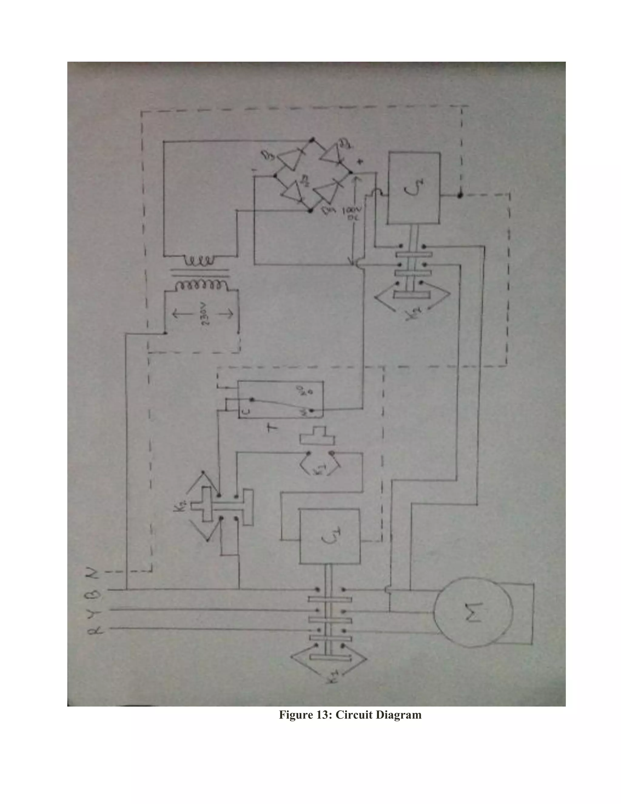
SlideShare a Scribd company logo
MANMOHAN MEMORIAL POLYTECHNIC
DEPARTMENT OF ELECTRICAL ENGINEERING
PROJECT REPORT ON
“DC INJECTION BRAKING OF INDUCTION MOTOR”
Prepared by:
Arun Thapa (7120010)
Arjun Dhimal (7120009)
Meghraj Basnet (7120019)
Lokmani Bhandari (7120017)
Utshab Rana (7120047)
Samartha Dhungana (7120032)
Aman Kumar Shah (7120004)
(2071-74 Batch)
Under the supervision of :
Er. Khagendra Sapkota
Submitted to :
Department of Electrical Engineering(MMP)
Date 2074-04-11 BS
MANMOHAN MEMORIAL POLYTECHNIC
DEPARTMENT OF ELECTRICAL ENGINEERING
Hattimuda-7, Morang
CERTIFICATE
This is to certify that this thesis titled “DC INJECTION BRAKING OF INDUCTION
MOTOTR” is the bonafide work, which carried out final year project work under the well
supervision of Er. Khagendra Sapkota (Asst. lecturer) of Electrical Department. It is certified
further that to the best of knowledge the work reported here in doesn’t form part of any other
thesis or dissertation on the basis of which a degree or reward was conferred on an earlier
occasion on this any other candidate.
Roll no: Name of student Student's id number
10 Arun Thapa 7120010
09 Arjun Dhimal 7120009
19 Meghraj Basnet 7120019
17 Lokmani Bhandari 7120017
47 Utshab Rana 7120047
32 Samartha Dhungana 7120032
04 Aman Kumar Shah 7120004
……………… ………………….
Signature Signature
Er. Khagendra Sapkota Er. Ram Kumar Yadav
Supervisor coordinator
………………………
Signature
Dr. Subash Shree Pokhrel
Principal
Abstract
The project DC injection braking of Induction Motor aims at braking of 3-Phase Induction
Motor. This is done by disconnecting 3-phase supply from motor and connecting DC supply to
any one winding of motor. Due to constant flux created by DC supply motor gets brake. Higher
the DC voltage the brake will be strong. Two contactor,3 transformer in series to obtain 110 V, 1
timer switch, 2 NO NC switch, indicating bulb, rectifier circuit and Motor are the components
used in this project. One main contactor is used for main 2-phase supply and another one for DC
supply. Under motor running condition main contactor in energized when we de-energized main
contactor another contactor is energized and inject DC to the winding which cause brake on the
motor. DC supply is obtained by stepped down the voltage and further rectify with bridge
rectifier. Timer switch is use on the line supply of contactor use for DC for disconnecting this
contactor after brake is done. This is to be done to prevent winding from damage because DC
supply on winding for more than necessary cause damage to the winding.
Aknowledgement
We would like to express our gratitude to all those who gave us the possibility to complete this
project. We want to thank the Department of Electrical Engineering for giving us opportunity to
commence this project in the first instance and to do the necessary research work. We have
furthermore to thank our classmates and seniors who helped us and encouraged me to go ahead
with our project.
We are deeply indebted to our supervisor Asst. Lecturer Er. Khagendra Sapkota whose help,
stimulating suggestions and encouragement helped us in all the time of completeion of this
project.
Table of contents
CHAPTER 1 .................................................................................................................................................7
INTRODUCTION ........................................................................................................................................7
1.1 Background and objectives...........................................................................................................7
1.1.1 Background...........................................................................................................................7
1.1.2 Objectives .............................................................................................................................7
1.2 Application....................................................................................................................................8
1.3 System Overview..........................................................................................................................9
1.3.1 Block Diagram.............................................................................................................................9
1.3.2 Block Diagram Description .......................................................................................................10
1.4 Methodology.....................................................................................................................................11
CHAPTER 2 ...............................................................................................................................................12
2.1 Contactor...........................................................................................................................................12
2.3 Timer Switch.....................................................................................................................................14
2.4 NO NC Switch..................................................................................................................................15
2.5 Bridge Rectifier.................................................................................................................................16
2.6 Induction Motor ................................................................................................................................17
2.7 Indicating Bulb..................................................................................................................................18
CHAPTER 3 ...............................................................................................................................................19
3.1 DOL stator circuit .............................................................................................................................19
3.2 Rectifier Circuit ................................................................................................................................20
3.3 Contactor with Timer Switch............................................................................................................21
CHAPTER 4 ...............................................................................................................................................22
PRODUCT DESCRIPTION AND PERFORMANCE...............................................................................22
CHAPTER 5 ...............................................................................................................................................25
DISCUSSION AND CONCLUSION.........................................................................................................25
5.1 Work Accomplished .........................................................................................................................25
5.2 Problem Faced ..................................................................................................................................25
CONCLUSION...........................................................................................................................................26
Table of Figures
Figure 1: Block Diagram ..............................................................................................................................9
Figure 2: Methodology ...............................................................................................................................11
Figure 3: Contactor .....................................................................................................................................12
Figure 4: Transformer.................................................................................................................................13
Figure 5: Timer Switch...............................................................................................................................14
Figure 6: NO NC Switch.............................................................................................................................15
Figure 7: Bridge Rectifier...........................................................................................................................16
Figure 8: 3-Phase IM ..................................................................................................................................17
Figure 9: Indicating Bulb............................................................................................................................18
Figure 10: DOL stator circuit......................................................................................................................19
Figure 11: Rectifier circuit..........................................................................................................................20
Figure 12: Contactor with timer switch ......................................................................................................21
Figure 13: Circuit Diagram.........................................................................................................................23
Figure 14: DC injection braking of IM .......................................................................................................24
CHAPTER 1
INTRODUCTION
1.1Background and objectives
1.1.1 Background
DC injection braking is a method of slowing AC electric motors. A DC voltage is injected into
the winding of the AC motor after the AC voltage is disconnected, providing braking force to the
rotor. A DC voltage is applied to the motor windings, creating a stationary magnetic field which
applies a static torque to the rotor. This slows and eventually halts the rotor completely. As long
as the DC voltage is applied to the windings, the rotor will be held in position and resistant to
any attempt to spin it. The higher the voltage that is applied, the stronger the braking force and
holding power. DC injection brakes can also be used for emergency braking, when the motor
needs to be stopped immediately for whatever reason.
Transformer is used for step down the voltage and low voltage is further rectifying by bridge
rectifier for DC supply. Timer switch is used for disconnect the dc supply after certain time. In
DC injection braking system DC should not be injected for a long time (i.e. more than necessary)
as this will damage the stator coil of motor.
1.1.2 Objectives
The main objectives of this project are:
1) To rapidly and safely stop an induction motor.
2) To reduce the problem caused during mechanical brake.
3) To deliver high levels of torque to stop the motor.
4) To save the time if the motor must be stopped and restarted multiple times during the
course of a work day.
1.2Application
The main application of this project is in industries where motor needs to stop and starts
frequently and during accident this can protect from serious injure. Application of this project is
in industries like:-
1) Rolling mills
2) Cut-off saws
3) Rubber mills
4) Rock crushers etc
1.3System Overview
1.3.1 Block Diagram
Figure 1: Block Diagram
3-Phase supply
Main contactor
3-Phase Motor
Transformer
Bridge Rectifier
Timer Switch
Contactor for DC
Supply
Running
Indicator
Brake
Indicator
Single phase supply
1.3.2 Block Diagram Description
Figure: 1 shows the block diagram of our project. Three phase supply of 400 V 50 Hz is given to
the 3-Phase Induction motor through main contactor . Single phase supply is tapped from 3 phase
supply for operation of contactor, timer and single phase transformer. An AC supply voltage of
230 V 50 Hz is stepped down by transformer to 110 V. The secondary output is rectified by a
full-wave bridge rectifier.
Rectified DC is connected to any one winding of motor passing through contactor as shown in
block diagram. For the operation of contactor for DC supply, single phase supply is given by
passing through timer switch. Timer switch is connected in NC contact. The purpose of using
timer switch is to disconnect DC supply after braking is done. Two indicators are used in our
project for indication of running and braking of motor. Running indicator is connected parallel to
main contactor and braking indicator is connected parallel to contactor for DC supply as shown
in figure: 1.
1.4 Methodology
First, we surveyed for the detailed theory and principles used in our project. Secondly, we
surveyed about the components used and their availability. The power supply and the braking
circuit of the project have been fabricated on plywood board. Testing and repairing was done and
finally braking was done on induction motor.
FINAL TESTING
FABRICATION
PROJECT SELECTION
LITERATURE SURVEY
MARKET SURVEY
DESIGNING
ASSEMBLING
TESTING AND
MAINTAINING
Figure 2: Methodology
CHAPTER 2
TECHNOLOGY AND LITERATURE SURVEY
The project DC Injection Braking Of Induction Motor aims at braking of a motor by
disconnecting AC supply and injecting DC supply. Brief descriptions of components used in this
project are given below.
2.1 Contactor
A contactor is an electrically controlled switch used for switching an electrical power circuit,
similar to relay expects with high current ratings. A contactor is typically controlled by a circuit
which has a much lower power level than the switched circuit, such as a 230 V coil
electromagnet controlling a 400 V motor switch. Contactor is a NO switched at normal condition
when its coil gets energized then switch gets contacts. Contactor also contain auxiliary contact
(i.e. NO and NC).
Two contactors are used in this project. One for main three phase supply for motor and another
for DC supply.
Figure 3: Contactor
2.2Transformer
Transformer is an electrical component that works on the principal of Faraday’s law of induction
by converting electrical energy from one value to another where power and frequency remain
constant. Transformer does this by linking together two or more electrical circuits using a
common oscillating magnetic circuit which is produced by the transformer itself.
Transformer is used for step down 230 V into 110 V in this project. The purpose of stepped
down is for rectification. Rated current is of 4 amp.
Figure 4: Transformer
2.3 Timer Switch
Timer switch is a timer that operates an electric switch controlled by the timing mechanism. It consist of
supply terminal, comment point, NO and NC contact. Supply power is given from the supply terminal A1 and
A2. The incoming line is connected to common point and as required we can connect outgoing line to NO or
NC point. Required time can be set from the selector. At normal condition common point is in contact with NC
point but after set time reached the common point gets contact with NO point and that is how timer switch
works.
In this project timer switch is used for disconnecting the DC supply from the motor after brake is done. The
timer switch operates the contactor which is use for DC supply. Contactor is connected to NC point of the
timer switch. When timer switch gets supply then the contactor too gets supply and after set time reached then
the contactor gets disconnected.
Figure 5: Timer Switch
2.4 NO NC Switch
NO is normally open i.e. the contacts are normally open and close when the switch is
actuated.NC is normally closed i.e. the contacts are normally closed and open when the switch
is actuated.NO NC is generally used to describe contactors and manual switches like
emergency stop buttons. It means that there is one pair of normally closed and one pair of
normally open contacts with their own terminals i.e. there will be four terminals. NO terminal
is used for starting the motor and NC is used to disconnect the supply (i.e. to stop the motor).
In this project two switches are used. One for starting the motor by providing supply to
contactor and another for disconnecting the supply for contactor which disconnect the motor
supply. For NO switch holding patch should be provide so that supply doesn’t get disconnect
after releasing the button. Auxiliary contact of the contactor provides the holding path.
Figure 6: NO NC Switch
2.5 Bridge Rectifier
This type of single phase rectifier uses four individual rectifying diodes connected in a closed
loop “bridge” configuration to produce the desired output. The main advantage of this bridge
circuit is that it does not require a special center tapped transformer, thereby reducing its size and
cost. The single secondary winding is connected to one side of the diode bridge network and the
load to the other side.
The four diodes labeled D1 to D4 are arranged in “series pairs” with only two diodes conducting
current during each half cycle. During the positive half cycle of the supply,
diodes D3 and D2 conduct in series while diodes D3 and D4 are reverse biased and the current
flows through the load. The purpose of rectifying is to get DC output for braking of motor. The
DC output obtained for this project is 100 V.
Figure 7: Bridge Rectifier
2.6 Induction Motor
Figure 8: 3-Phase IM
An induction motor, 3 phase induction motor or asynchronous motor is an AC electric motor in
which the electric current in the rotor needed to produce torque is obtained by electromagnetic
induction from the magnetic field of the stator winding. An induction motor can therefore be
made without electrical connections to the rotor. An induction motor's rotor can be either wound
type or squirrel-cage type.
In this project IM of 2 HP is used for braking which runs on 380 V 50 Hz having 3.7 Amp rated
current. Speed of this motor is 1450 rpm.
2.7 Indicating Bulb
Indicating bulb is used for indicate while running and braking of IM. Green light glow while
running and red light indicate that motor is brake. Green bulb is connected in parallel with main
contactor and red light is connected in parallel with the contactor which is used for DC supply
for braking purpose. The bulb is of 5 watt each.
Figure 9: Indicating Bulb
CHAPTER 3
SYSTEM ANALYSIS AND EXPERIMENT
Our project consists of following circuit:
 DOL stator circuit
 Rectifier circuit
 Contactor with timer circuit
3.1 DOL stator circuit
Different starting methods are employed for starting induction motors because Induction
Motor draws more starting current during starting. To prevent damage to the windings due to
the high starting current flow, we employ different types of starters.
The simplest form of motor starter for the induction motor is the Direct on Line starter. The
DOL starter consist a MCCB, Contactor and an overload relay for protection. Typically, the
contactor will be controlled by separate start and stop buttons, and an auxiliary contact on the
contactor is used, across the start button, as a hold in contact. i.e. the contactor is electrically
latched closed while the motor is operating.
Motor
Figure 10: DOL stator circuit
3.2 Rectifier Circuit
A Full wave rectifier is a circuit arrangement which makes use of both half cycles of input
alternating current (AC) and converts them to direct current (DC). A half wave rectifier makes
use of only one half cycle of the input alternating current. Thus a full wave rectifier is much
more efficient (double+) than a half wave rectifier. This process of converting both half cycles of
the input supply (alternating current) to direct current (DC) is termed full wave rectification.
Above figure shows the circuit arrangement of bridge rectifier which is used in this project. Here
in this project we stepped down 230 V into 110 V and with the help of bridge rectifier we
convert 110 V AC into DC for braking purpose.
Tomotorwinding
Figure 11: Rectifier circuit
3.3 Contactor with Timer Switch
+ - N P
C T
Above figure shows the circuit diagram for operation of contactor with timer switch. In this
project we use timer switch for disconnect of contactor from providing DC supply to winding.
Providing DC supply for a long time creates heat on winding and may get damaged.
In this project contactor is connected with NC on timer switch which means it gets supply on
normal condition. When set time reached its value then timer switch trip to NO contact and make
open circuit for contactor and that is how this circuit works.
NC NO
Figure 12: Contactor with timer switch
CHAPTER 4
PRODUCT DESCRIPTION AND PERFORMANCE
As discussed in chapter 3 we have used several circuits for the running of this project which are
listed below Once again.
 DOL stator circuit
 Rectifier circuit
 Contactor with timer circuit
The supply for operation of Induction motor required 3 phase 50 Hz and was provided using
DOL stator. 220 V was stepped down to 110V with the help of step down transformer. The
output obtained at secondary side of transformer was rectified with the help of full wave bridge
rectifier. The DC obtained from bridge rectifier was connected to one winding of motor passing
through the contactor.
Contactor use for DC supply was controlled with timer switch. Timer switch gets supply when
main contactor gets disconnect. This was done by connection of timer switch with the NO
contact of same switch which was made connection with NC contact of main contactor. For
holding contact for this timer the terminal of NO contact was connected with auxiliary contact of
second contactor as shown in circuit diagram below. With this when we press button for stop the
main contactor gets de-energized and timer as well and second contactor gets supply with this
AC supply gets disconnect and DC supply gets into one winding of Motor. This is how this
project works and motor gets brake and so called DC injection braking. Timer should be set to 2-
4 sec so that it will disconnect DC supply from winding.
The output obtained from this project is very efficient. The motor stops within a second with this
project whereas without using DC injection braking the motor takes 20 sec to be in complete
rest. That’s how this project saves time.
Figure 13: Circuit Diagram
Figure 14: DC injection braking of IM
CHAPTER 5
DISCUSSION AND CONCLUSION
5.1 Work Accomplished
Following are the work done to complete this project:-
 Designed the power supply and braking circuit.
 Assembled all components and connection was done on plywood according to circuit.
 Tested the circuit without connection of motor.
 Tested the project with motor and get succeed to brake perfectly.
 Finishing was given by painting on plywood and providing stand to the panel board.
5.2 Problem Faced
Following were the problems faced during this project:-
 Unavailability of components on lab.
 Unavailability of some components on market.
 Problems while exchanging the component with different rating of same type from where we
brought.
CONCLUSION
This project has helped us to learn the practical aspects of the knowledge we gained so far
through different courses. The practical aspect of the theoritical component is learned along with
the confidence to connect the complex circuit in board. We learnt a lot about electric braking
system, its advantage over mechanical braking and many more . The technical and practical field
knowledge required in handling project is achieved. Thus working in this project has been an
assets for us and we have been benefited from the experience gained during its completion.
References
Following references are taken for this project
(1) www.wikipedia.com
(2) www.electricalforyou.com
(3) www.easyelectrical.com
(4) Text book of electrical engineering by Bl theraja (Reprinted in 2008)
(5) Lectures notes

More Related Content

What's hot

Simple Low Power Inverter Convert 12V DC into 230AC
Simple Low Power Inverter Convert 12V DC into 230ACSimple Low Power Inverter Convert 12V DC into 230AC
Simple Low Power Inverter Convert 12V DC into 230AC
Radharaman Group Of Institutes,Bhopal,M.P.
 
Get Complete Information about Circuit Breaker
Get Complete Information about Circuit BreakerGet Complete Information about Circuit Breaker
Get Complete Information about Circuit Breaker
System Protection
 
Brushless DC Motors
Brushless DC MotorsBrushless DC Motors
Brushless DC Motors
Deepak Kumar Mohapatra
 
Speed Control of BLDC Motor with Four Quadrant Operation Using dsPIC
Speed Control of BLDC Motor with Four Quadrant Operation Using dsPICSpeed Control of BLDC Motor with Four Quadrant Operation Using dsPIC
Speed Control of BLDC Motor with Four Quadrant Operation Using dsPIC
ijsrd.com
 
Linear Induction Motor
Linear Induction MotorLinear Induction Motor
Linear Induction Motor
Ajit Singh Rajawat
 
Single Phase Induction Motor Speed Control
Single Phase Induction Motor Speed ControlSingle Phase Induction Motor Speed Control
Single Phase Induction Motor Speed Control
Edgefxkits & Solutions
 
Thyristor switched capacitor
Thyristor switched capacitorThyristor switched capacitor
Thyristor switched capacitor
KLS' S GIT, BELGAUM
 
Distribution Transformer Design (Electrical Machine Design)
Distribution Transformer Design (Electrical Machine Design)Distribution Transformer Design (Electrical Machine Design)
Distribution Transformer Design (Electrical Machine Design)
Md. Rayid Hasan Mojumder
 
A presentation on inverter by manoj
A presentation on inverter by manojA presentation on inverter by manoj
A presentation on inverter by manoj
IACM SmartLearn Ltd.
 
DISTANCE PROTECTION RELAY
DISTANCE PROTECTION RELAYDISTANCE PROTECTION RELAY
DISTANCE PROTECTION RELAY
Raviraj solanki
 
Power Transformer in DPL
Power Transformer in DPLPower Transformer in DPL
Power Transformer in DPL
Abhishek Roy
 
Differential Relay.pptx
Differential Relay.pptxDifferential Relay.pptx
Differential Relay.pptx
MahmoudMustafa84
 
Electric Drives and Controls Unit 1 Introduction
Electric Drives and Controls Unit 1 IntroductionElectric Drives and Controls Unit 1 Introduction
Electric Drives and Controls Unit 1 Introduction
Dr.Raja R
 
Armature reaction and parallel operation of a Syncronous generator
Armature reaction and parallel operation of a Syncronous generatorArmature reaction and parallel operation of a Syncronous generator
Armature reaction and parallel operation of a Syncronous generator
karthi1017
 
Control of hvdc system
Control of hvdc systemControl of hvdc system
Control of hvdc system
Aazim Rasool
 
Electrical Machines - II
Electrical Machines - IIElectrical Machines - II
Electrical Machines - II
karthi1017
 
Split phase motor.pptx
Split phase motor.pptxSplit phase motor.pptx
Split phase motor.pptx
AmeerHamza842286
 
Resonant Converter
Resonant ConverterResonant Converter
Resonant Converter
pilurout
 
vector control of induction motor
vector control of induction motorvector control of induction motor
vector control of induction motor
Dwaraka Pilla
 
EMF EQUATION OF DC GENERATOR,DC MOTOR|DAY15|BACK EMF,TORQUE OF DC MOTOR|BASIC...
EMF EQUATION OF DC GENERATOR,DC MOTOR|DAY15|BACK EMF,TORQUE OF DC MOTOR|BASIC...EMF EQUATION OF DC GENERATOR,DC MOTOR|DAY15|BACK EMF,TORQUE OF DC MOTOR|BASIC...
EMF EQUATION OF DC GENERATOR,DC MOTOR|DAY15|BACK EMF,TORQUE OF DC MOTOR|BASIC...
Prasant Kumar
 

What's hot (20)

Simple Low Power Inverter Convert 12V DC into 230AC
Simple Low Power Inverter Convert 12V DC into 230ACSimple Low Power Inverter Convert 12V DC into 230AC
Simple Low Power Inverter Convert 12V DC into 230AC
 
Get Complete Information about Circuit Breaker
Get Complete Information about Circuit BreakerGet Complete Information about Circuit Breaker
Get Complete Information about Circuit Breaker
 
Brushless DC Motors
Brushless DC MotorsBrushless DC Motors
Brushless DC Motors
 
Speed Control of BLDC Motor with Four Quadrant Operation Using dsPIC
Speed Control of BLDC Motor with Four Quadrant Operation Using dsPICSpeed Control of BLDC Motor with Four Quadrant Operation Using dsPIC
Speed Control of BLDC Motor with Four Quadrant Operation Using dsPIC
 
Linear Induction Motor
Linear Induction MotorLinear Induction Motor
Linear Induction Motor
 
Single Phase Induction Motor Speed Control
Single Phase Induction Motor Speed ControlSingle Phase Induction Motor Speed Control
Single Phase Induction Motor Speed Control
 
Thyristor switched capacitor
Thyristor switched capacitorThyristor switched capacitor
Thyristor switched capacitor
 
Distribution Transformer Design (Electrical Machine Design)
Distribution Transformer Design (Electrical Machine Design)Distribution Transformer Design (Electrical Machine Design)
Distribution Transformer Design (Electrical Machine Design)
 
A presentation on inverter by manoj
A presentation on inverter by manojA presentation on inverter by manoj
A presentation on inverter by manoj
 
DISTANCE PROTECTION RELAY
DISTANCE PROTECTION RELAYDISTANCE PROTECTION RELAY
DISTANCE PROTECTION RELAY
 
Power Transformer in DPL
Power Transformer in DPLPower Transformer in DPL
Power Transformer in DPL
 
Differential Relay.pptx
Differential Relay.pptxDifferential Relay.pptx
Differential Relay.pptx
 
Electric Drives and Controls Unit 1 Introduction
Electric Drives and Controls Unit 1 IntroductionElectric Drives and Controls Unit 1 Introduction
Electric Drives and Controls Unit 1 Introduction
 
Armature reaction and parallel operation of a Syncronous generator
Armature reaction and parallel operation of a Syncronous generatorArmature reaction and parallel operation of a Syncronous generator
Armature reaction and parallel operation of a Syncronous generator
 
Control of hvdc system
Control of hvdc systemControl of hvdc system
Control of hvdc system
 
Electrical Machines - II
Electrical Machines - IIElectrical Machines - II
Electrical Machines - II
 
Split phase motor.pptx
Split phase motor.pptxSplit phase motor.pptx
Split phase motor.pptx
 
Resonant Converter
Resonant ConverterResonant Converter
Resonant Converter
 
vector control of induction motor
vector control of induction motorvector control of induction motor
vector control of induction motor
 
EMF EQUATION OF DC GENERATOR,DC MOTOR|DAY15|BACK EMF,TORQUE OF DC MOTOR|BASIC...
EMF EQUATION OF DC GENERATOR,DC MOTOR|DAY15|BACK EMF,TORQUE OF DC MOTOR|BASIC...EMF EQUATION OF DC GENERATOR,DC MOTOR|DAY15|BACK EMF,TORQUE OF DC MOTOR|BASIC...
EMF EQUATION OF DC GENERATOR,DC MOTOR|DAY15|BACK EMF,TORQUE OF DC MOTOR|BASIC...
 

Similar to DC-injection Braking

Automatic Phase Changer
Automatic Phase ChangerAutomatic Phase Changer
Automatic Phase Changer
Bhanu Bhawesh
 
Irrigation
IrrigationIrrigation
Irrigation
Jaya Lakshmi
 
Sushant 131119022958-phpapp02
Sushant 131119022958-phpapp02Sushant 131119022958-phpapp02
Sushant 131119022958-phpapp02
K. Suresh Kumar
 
13EC 17014.docx
13EC 17014.docx13EC 17014.docx
13EC 17014.docx
Chitanshu Chauhan
 
Automatic Plant Irrigator -Mini Project ECE(without micro controller)
Automatic Plant Irrigator -Mini Project ECE(without micro controller) Automatic Plant Irrigator -Mini Project ECE(without micro controller)
Automatic Plant Irrigator -Mini Project ECE(without micro controller)
Sushant Shankar
 
automatic phase changer in three phase supply
automatic phase changer in three phase supplyautomatic phase changer in three phase supply
automatic phase changer in three phase supply
amaljo joju e
 
HAZRAT PROJECT
HAZRAT PROJECTHAZRAT PROJECT
HAZRAT PROJECT
hazrat081
 
Brushless DC Excitation Systems
Brushless DC Excitation SystemsBrushless DC Excitation Systems
Brushless DC Excitation Systems
Sharmili Palli
 
Final report
Final reportFinal report
Final report
Debashish Gorai
 
Transient stability analysis
Transient stability analysisTransient stability analysis
Transient stability analysis
Arnab Nandi
 
GSM Automated System For Monitoring And Controlling
 GSM Automated System  For Monitoring And Controlling  GSM Automated System  For Monitoring And Controlling
GSM Automated System For Monitoring And Controlling
meerkhan627
 
Simulation based minor project on Buck converter( DC to Dc step down Converter)
Simulation based minor project on Buck converter( DC to Dc step down Converter)Simulation based minor project on Buck converter( DC to Dc step down Converter)
Simulation based minor project on Buck converter( DC to Dc step down Converter)
Ashutosh Singh
 
2ji12ec413
2ji12ec4132ji12ec413
2ji12ec413
unmesh Hanamshet
 
Project report of kota super thermal power plant
Project report of kota super thermal power plantProject report of kota super thermal power plant
Project report of kota super thermal power plant
Hîmãńshu Mêęńä
 
Doc a.7-tlc report
Doc a.7-tlc reportDoc a.7-tlc report
Doc a.7-tlc report
9951081577
 
Automatic power factor_detection_and_cor
Automatic power factor_detection_and_corAutomatic power factor_detection_and_cor
Automatic power factor_detection_and_cor
hadafree
 
Minor Project Report: Automatic Door Control System
Minor Project Report: Automatic Door Control SystemMinor Project Report: Automatic Door Control System
Minor Project Report: Automatic Door Control System
Saban Kumar K.C.
 
Automatic street light control using LDR.
Automatic street light control using LDR.Automatic street light control using LDR.
Automatic street light control using LDR.
Fazlur Rahman
 
Automatic street light control using LDR.
Automatic street light control using LDR.Automatic street light control using LDR.
Automatic street light control using LDR.
Fazlur Rahman
 
electronic circuit breaker report by saurabh chauhan
electronic circuit breaker report by saurabh chauhanelectronic circuit breaker report by saurabh chauhan
electronic circuit breaker report by saurabh chauhan
saurabh chauhan
 

Similar to DC-injection Braking (20)

Automatic Phase Changer
Automatic Phase ChangerAutomatic Phase Changer
Automatic Phase Changer
 
Irrigation
IrrigationIrrigation
Irrigation
 
Sushant 131119022958-phpapp02
Sushant 131119022958-phpapp02Sushant 131119022958-phpapp02
Sushant 131119022958-phpapp02
 
13EC 17014.docx
13EC 17014.docx13EC 17014.docx
13EC 17014.docx
 
Automatic Plant Irrigator -Mini Project ECE(without micro controller)
Automatic Plant Irrigator -Mini Project ECE(without micro controller) Automatic Plant Irrigator -Mini Project ECE(without micro controller)
Automatic Plant Irrigator -Mini Project ECE(without micro controller)
 
automatic phase changer in three phase supply
automatic phase changer in three phase supplyautomatic phase changer in three phase supply
automatic phase changer in three phase supply
 
HAZRAT PROJECT
HAZRAT PROJECTHAZRAT PROJECT
HAZRAT PROJECT
 
Brushless DC Excitation Systems
Brushless DC Excitation SystemsBrushless DC Excitation Systems
Brushless DC Excitation Systems
 
Final report
Final reportFinal report
Final report
 
Transient stability analysis
Transient stability analysisTransient stability analysis
Transient stability analysis
 
GSM Automated System For Monitoring And Controlling
 GSM Automated System  For Monitoring And Controlling  GSM Automated System  For Monitoring And Controlling
GSM Automated System For Monitoring And Controlling
 
Simulation based minor project on Buck converter( DC to Dc step down Converter)
Simulation based minor project on Buck converter( DC to Dc step down Converter)Simulation based minor project on Buck converter( DC to Dc step down Converter)
Simulation based minor project on Buck converter( DC to Dc step down Converter)
 
2ji12ec413
2ji12ec4132ji12ec413
2ji12ec413
 
Project report of kota super thermal power plant
Project report of kota super thermal power plantProject report of kota super thermal power plant
Project report of kota super thermal power plant
 
Doc a.7-tlc report
Doc a.7-tlc reportDoc a.7-tlc report
Doc a.7-tlc report
 
Automatic power factor_detection_and_cor
Automatic power factor_detection_and_corAutomatic power factor_detection_and_cor
Automatic power factor_detection_and_cor
 
Minor Project Report: Automatic Door Control System
Minor Project Report: Automatic Door Control SystemMinor Project Report: Automatic Door Control System
Minor Project Report: Automatic Door Control System
 
Automatic street light control using LDR.
Automatic street light control using LDR.Automatic street light control using LDR.
Automatic street light control using LDR.
 
Automatic street light control using LDR.
Automatic street light control using LDR.Automatic street light control using LDR.
Automatic street light control using LDR.
 
electronic circuit breaker report by saurabh chauhan
electronic circuit breaker report by saurabh chauhanelectronic circuit breaker report by saurabh chauhan
electronic circuit breaker report by saurabh chauhan
 

Recently uploaded

CSM Cloud Service Management Presentarion
CSM Cloud Service Management PresentarionCSM Cloud Service Management Presentarion
CSM Cloud Service Management Presentarion
rpskprasana
 
Literature Review Basics and Understanding Reference Management.pptx
Literature Review Basics and Understanding Reference Management.pptxLiterature Review Basics and Understanding Reference Management.pptx
Literature Review Basics and Understanding Reference Management.pptx
Dr Ramhari Poudyal
 
Eric Nizeyimana's document 2006 from gicumbi to ttc nyamata handball play
Eric Nizeyimana's document 2006 from gicumbi to ttc nyamata handball playEric Nizeyimana's document 2006 from gicumbi to ttc nyamata handball play
Eric Nizeyimana's document 2006 from gicumbi to ttc nyamata handball play
enizeyimana36
 
Electric vehicle and photovoltaic advanced roles in enhancing the financial p...
Electric vehicle and photovoltaic advanced roles in enhancing the financial p...Electric vehicle and photovoltaic advanced roles in enhancing the financial p...
Electric vehicle and photovoltaic advanced roles in enhancing the financial p...
IJECEIAES
 
Textile Chemical Processing and Dyeing.pdf
Textile Chemical Processing and Dyeing.pdfTextile Chemical Processing and Dyeing.pdf
Textile Chemical Processing and Dyeing.pdf
NazakatAliKhoso2
 
Heat Resistant Concrete Presentation ppt
Heat Resistant Concrete Presentation pptHeat Resistant Concrete Presentation ppt
Heat Resistant Concrete Presentation ppt
mamunhossenbd75
 
Engine Lubrication performance System.pdf
Engine Lubrication performance System.pdfEngine Lubrication performance System.pdf
Engine Lubrication performance System.pdf
mamamaam477
 
ACEP Magazine edition 4th launched on 05.06.2024
ACEP Magazine edition 4th launched on 05.06.2024ACEP Magazine edition 4th launched on 05.06.2024
ACEP Magazine edition 4th launched on 05.06.2024
Rahul
 
Understanding Inductive Bias in Machine Learning
Understanding Inductive Bias in Machine LearningUnderstanding Inductive Bias in Machine Learning
Understanding Inductive Bias in Machine Learning
SUTEJAS
 
132/33KV substation case study Presentation
132/33KV substation case study Presentation132/33KV substation case study Presentation
132/33KV substation case study Presentation
kandramariana6
 
Advanced control scheme of doubly fed induction generator for wind turbine us...
Advanced control scheme of doubly fed induction generator for wind turbine us...Advanced control scheme of doubly fed induction generator for wind turbine us...
Advanced control scheme of doubly fed induction generator for wind turbine us...
IJECEIAES
 
KuberTENes Birthday Bash Guadalajara - K8sGPT first impressions
KuberTENes Birthday Bash Guadalajara - K8sGPT first impressionsKuberTENes Birthday Bash Guadalajara - K8sGPT first impressions
KuberTENes Birthday Bash Guadalajara - K8sGPT first impressions
Victor Morales
 
22CYT12-Unit-V-E Waste and its Management.ppt
22CYT12-Unit-V-E Waste and its Management.ppt22CYT12-Unit-V-E Waste and its Management.ppt
22CYT12-Unit-V-E Waste and its Management.ppt
KrishnaveniKrishnara1
 
学校原版美国波士顿大学毕业证学历学位证书原版一模一样
学校原版美国波士顿大学毕业证学历学位证书原版一模一样学校原版美国波士顿大学毕业证学历学位证书原版一模一样
学校原版美国波士顿大学毕业证学历学位证书原版一模一样
171ticu
 
basic-wireline-operations-course-mahmoud-f-radwan.pdf
basic-wireline-operations-course-mahmoud-f-radwan.pdfbasic-wireline-operations-course-mahmoud-f-radwan.pdf
basic-wireline-operations-course-mahmoud-f-radwan.pdf
NidhalKahouli2
 
Recycled Concrete Aggregate in Construction Part II
Recycled Concrete Aggregate in Construction Part IIRecycled Concrete Aggregate in Construction Part II
Recycled Concrete Aggregate in Construction Part II
Aditya Rajan Patra
 
Manufacturing Process of molasses based distillery ppt.pptx
Manufacturing Process of molasses based distillery ppt.pptxManufacturing Process of molasses based distillery ppt.pptx
Manufacturing Process of molasses based distillery ppt.pptx
Madan Karki
 
Presentation of IEEE Slovenia CIS (Computational Intelligence Society) Chapte...
Presentation of IEEE Slovenia CIS (Computational Intelligence Society) Chapte...Presentation of IEEE Slovenia CIS (Computational Intelligence Society) Chapte...
Presentation of IEEE Slovenia CIS (Computational Intelligence Society) Chapte...
University of Maribor
 
Casting-Defect-inSlab continuous casting.pdf
Casting-Defect-inSlab continuous casting.pdfCasting-Defect-inSlab continuous casting.pdf
Casting-Defect-inSlab continuous casting.pdf
zubairahmad848137
 
The Python for beginners. This is an advance computer language.
The Python for beginners. This is an advance computer language.The Python for beginners. This is an advance computer language.
The Python for beginners. This is an advance computer language.
sachin chaurasia
 

Recently uploaded (20)

CSM Cloud Service Management Presentarion
CSM Cloud Service Management PresentarionCSM Cloud Service Management Presentarion
CSM Cloud Service Management Presentarion
 
Literature Review Basics and Understanding Reference Management.pptx
Literature Review Basics and Understanding Reference Management.pptxLiterature Review Basics and Understanding Reference Management.pptx
Literature Review Basics and Understanding Reference Management.pptx
 
Eric Nizeyimana's document 2006 from gicumbi to ttc nyamata handball play
Eric Nizeyimana's document 2006 from gicumbi to ttc nyamata handball playEric Nizeyimana's document 2006 from gicumbi to ttc nyamata handball play
Eric Nizeyimana's document 2006 from gicumbi to ttc nyamata handball play
 
Electric vehicle and photovoltaic advanced roles in enhancing the financial p...
Electric vehicle and photovoltaic advanced roles in enhancing the financial p...Electric vehicle and photovoltaic advanced roles in enhancing the financial p...
Electric vehicle and photovoltaic advanced roles in enhancing the financial p...
 
Textile Chemical Processing and Dyeing.pdf
Textile Chemical Processing and Dyeing.pdfTextile Chemical Processing and Dyeing.pdf
Textile Chemical Processing and Dyeing.pdf
 
Heat Resistant Concrete Presentation ppt
Heat Resistant Concrete Presentation pptHeat Resistant Concrete Presentation ppt
Heat Resistant Concrete Presentation ppt
 
Engine Lubrication performance System.pdf
Engine Lubrication performance System.pdfEngine Lubrication performance System.pdf
Engine Lubrication performance System.pdf
 
ACEP Magazine edition 4th launched on 05.06.2024
ACEP Magazine edition 4th launched on 05.06.2024ACEP Magazine edition 4th launched on 05.06.2024
ACEP Magazine edition 4th launched on 05.06.2024
 
Understanding Inductive Bias in Machine Learning
Understanding Inductive Bias in Machine LearningUnderstanding Inductive Bias in Machine Learning
Understanding Inductive Bias in Machine Learning
 
132/33KV substation case study Presentation
132/33KV substation case study Presentation132/33KV substation case study Presentation
132/33KV substation case study Presentation
 
Advanced control scheme of doubly fed induction generator for wind turbine us...
Advanced control scheme of doubly fed induction generator for wind turbine us...Advanced control scheme of doubly fed induction generator for wind turbine us...
Advanced control scheme of doubly fed induction generator for wind turbine us...
 
KuberTENes Birthday Bash Guadalajara - K8sGPT first impressions
KuberTENes Birthday Bash Guadalajara - K8sGPT first impressionsKuberTENes Birthday Bash Guadalajara - K8sGPT first impressions
KuberTENes Birthday Bash Guadalajara - K8sGPT first impressions
 
22CYT12-Unit-V-E Waste and its Management.ppt
22CYT12-Unit-V-E Waste and its Management.ppt22CYT12-Unit-V-E Waste and its Management.ppt
22CYT12-Unit-V-E Waste and its Management.ppt
 
学校原版美国波士顿大学毕业证学历学位证书原版一模一样
学校原版美国波士顿大学毕业证学历学位证书原版一模一样学校原版美国波士顿大学毕业证学历学位证书原版一模一样
学校原版美国波士顿大学毕业证学历学位证书原版一模一样
 
basic-wireline-operations-course-mahmoud-f-radwan.pdf
basic-wireline-operations-course-mahmoud-f-radwan.pdfbasic-wireline-operations-course-mahmoud-f-radwan.pdf
basic-wireline-operations-course-mahmoud-f-radwan.pdf
 
Recycled Concrete Aggregate in Construction Part II
Recycled Concrete Aggregate in Construction Part IIRecycled Concrete Aggregate in Construction Part II
Recycled Concrete Aggregate in Construction Part II
 
Manufacturing Process of molasses based distillery ppt.pptx
Manufacturing Process of molasses based distillery ppt.pptxManufacturing Process of molasses based distillery ppt.pptx
Manufacturing Process of molasses based distillery ppt.pptx
 
Presentation of IEEE Slovenia CIS (Computational Intelligence Society) Chapte...
Presentation of IEEE Slovenia CIS (Computational Intelligence Society) Chapte...Presentation of IEEE Slovenia CIS (Computational Intelligence Society) Chapte...
Presentation of IEEE Slovenia CIS (Computational Intelligence Society) Chapte...
 
Casting-Defect-inSlab continuous casting.pdf
Casting-Defect-inSlab continuous casting.pdfCasting-Defect-inSlab continuous casting.pdf
Casting-Defect-inSlab continuous casting.pdf
 
The Python for beginners. This is an advance computer language.
The Python for beginners. This is an advance computer language.The Python for beginners. This is an advance computer language.
The Python for beginners. This is an advance computer language.
 

DC-injection Braking

  • 1. MANMOHAN MEMORIAL POLYTECHNIC DEPARTMENT OF ELECTRICAL ENGINEERING PROJECT REPORT ON “DC INJECTION BRAKING OF INDUCTION MOTOR” Prepared by: Arun Thapa (7120010) Arjun Dhimal (7120009) Meghraj Basnet (7120019) Lokmani Bhandari (7120017) Utshab Rana (7120047) Samartha Dhungana (7120032) Aman Kumar Shah (7120004) (2071-74 Batch) Under the supervision of : Er. Khagendra Sapkota Submitted to : Department of Electrical Engineering(MMP) Date 2074-04-11 BS
  • 2. MANMOHAN MEMORIAL POLYTECHNIC DEPARTMENT OF ELECTRICAL ENGINEERING Hattimuda-7, Morang CERTIFICATE This is to certify that this thesis titled “DC INJECTION BRAKING OF INDUCTION MOTOTR” is the bonafide work, which carried out final year project work under the well supervision of Er. Khagendra Sapkota (Asst. lecturer) of Electrical Department. It is certified further that to the best of knowledge the work reported here in doesn’t form part of any other thesis or dissertation on the basis of which a degree or reward was conferred on an earlier occasion on this any other candidate. Roll no: Name of student Student's id number 10 Arun Thapa 7120010 09 Arjun Dhimal 7120009 19 Meghraj Basnet 7120019 17 Lokmani Bhandari 7120017 47 Utshab Rana 7120047 32 Samartha Dhungana 7120032 04 Aman Kumar Shah 7120004 ……………… …………………. Signature Signature Er. Khagendra Sapkota Er. Ram Kumar Yadav Supervisor coordinator ……………………… Signature Dr. Subash Shree Pokhrel Principal
  • 3. Abstract The project DC injection braking of Induction Motor aims at braking of 3-Phase Induction Motor. This is done by disconnecting 3-phase supply from motor and connecting DC supply to any one winding of motor. Due to constant flux created by DC supply motor gets brake. Higher the DC voltage the brake will be strong. Two contactor,3 transformer in series to obtain 110 V, 1 timer switch, 2 NO NC switch, indicating bulb, rectifier circuit and Motor are the components used in this project. One main contactor is used for main 2-phase supply and another one for DC supply. Under motor running condition main contactor in energized when we de-energized main contactor another contactor is energized and inject DC to the winding which cause brake on the motor. DC supply is obtained by stepped down the voltage and further rectify with bridge rectifier. Timer switch is use on the line supply of contactor use for DC for disconnecting this contactor after brake is done. This is to be done to prevent winding from damage because DC supply on winding for more than necessary cause damage to the winding.
  • 4. Aknowledgement We would like to express our gratitude to all those who gave us the possibility to complete this project. We want to thank the Department of Electrical Engineering for giving us opportunity to commence this project in the first instance and to do the necessary research work. We have furthermore to thank our classmates and seniors who helped us and encouraged me to go ahead with our project. We are deeply indebted to our supervisor Asst. Lecturer Er. Khagendra Sapkota whose help, stimulating suggestions and encouragement helped us in all the time of completeion of this project.
  • 5. Table of contents CHAPTER 1 .................................................................................................................................................7 INTRODUCTION ........................................................................................................................................7 1.1 Background and objectives...........................................................................................................7 1.1.1 Background...........................................................................................................................7 1.1.2 Objectives .............................................................................................................................7 1.2 Application....................................................................................................................................8 1.3 System Overview..........................................................................................................................9 1.3.1 Block Diagram.............................................................................................................................9 1.3.2 Block Diagram Description .......................................................................................................10 1.4 Methodology.....................................................................................................................................11 CHAPTER 2 ...............................................................................................................................................12 2.1 Contactor...........................................................................................................................................12 2.3 Timer Switch.....................................................................................................................................14 2.4 NO NC Switch..................................................................................................................................15 2.5 Bridge Rectifier.................................................................................................................................16 2.6 Induction Motor ................................................................................................................................17 2.7 Indicating Bulb..................................................................................................................................18 CHAPTER 3 ...............................................................................................................................................19 3.1 DOL stator circuit .............................................................................................................................19 3.2 Rectifier Circuit ................................................................................................................................20 3.3 Contactor with Timer Switch............................................................................................................21 CHAPTER 4 ...............................................................................................................................................22 PRODUCT DESCRIPTION AND PERFORMANCE...............................................................................22 CHAPTER 5 ...............................................................................................................................................25 DISCUSSION AND CONCLUSION.........................................................................................................25 5.1 Work Accomplished .........................................................................................................................25 5.2 Problem Faced ..................................................................................................................................25 CONCLUSION...........................................................................................................................................26
  • 6. Table of Figures Figure 1: Block Diagram ..............................................................................................................................9 Figure 2: Methodology ...............................................................................................................................11 Figure 3: Contactor .....................................................................................................................................12 Figure 4: Transformer.................................................................................................................................13 Figure 5: Timer Switch...............................................................................................................................14 Figure 6: NO NC Switch.............................................................................................................................15 Figure 7: Bridge Rectifier...........................................................................................................................16 Figure 8: 3-Phase IM ..................................................................................................................................17 Figure 9: Indicating Bulb............................................................................................................................18 Figure 10: DOL stator circuit......................................................................................................................19 Figure 11: Rectifier circuit..........................................................................................................................20 Figure 12: Contactor with timer switch ......................................................................................................21 Figure 13: Circuit Diagram.........................................................................................................................23 Figure 14: DC injection braking of IM .......................................................................................................24
  • 7. CHAPTER 1 INTRODUCTION 1.1Background and objectives 1.1.1 Background DC injection braking is a method of slowing AC electric motors. A DC voltage is injected into the winding of the AC motor after the AC voltage is disconnected, providing braking force to the rotor. A DC voltage is applied to the motor windings, creating a stationary magnetic field which applies a static torque to the rotor. This slows and eventually halts the rotor completely. As long as the DC voltage is applied to the windings, the rotor will be held in position and resistant to any attempt to spin it. The higher the voltage that is applied, the stronger the braking force and holding power. DC injection brakes can also be used for emergency braking, when the motor needs to be stopped immediately for whatever reason. Transformer is used for step down the voltage and low voltage is further rectifying by bridge rectifier for DC supply. Timer switch is used for disconnect the dc supply after certain time. In DC injection braking system DC should not be injected for a long time (i.e. more than necessary) as this will damage the stator coil of motor. 1.1.2 Objectives The main objectives of this project are: 1) To rapidly and safely stop an induction motor. 2) To reduce the problem caused during mechanical brake. 3) To deliver high levels of torque to stop the motor. 4) To save the time if the motor must be stopped and restarted multiple times during the course of a work day.
  • 8. 1.2Application The main application of this project is in industries where motor needs to stop and starts frequently and during accident this can protect from serious injure. Application of this project is in industries like:- 1) Rolling mills 2) Cut-off saws 3) Rubber mills 4) Rock crushers etc
  • 9. 1.3System Overview 1.3.1 Block Diagram Figure 1: Block Diagram 3-Phase supply Main contactor 3-Phase Motor Transformer Bridge Rectifier Timer Switch Contactor for DC Supply Running Indicator Brake Indicator Single phase supply
  • 10. 1.3.2 Block Diagram Description Figure: 1 shows the block diagram of our project. Three phase supply of 400 V 50 Hz is given to the 3-Phase Induction motor through main contactor . Single phase supply is tapped from 3 phase supply for operation of contactor, timer and single phase transformer. An AC supply voltage of 230 V 50 Hz is stepped down by transformer to 110 V. The secondary output is rectified by a full-wave bridge rectifier. Rectified DC is connected to any one winding of motor passing through contactor as shown in block diagram. For the operation of contactor for DC supply, single phase supply is given by passing through timer switch. Timer switch is connected in NC contact. The purpose of using timer switch is to disconnect DC supply after braking is done. Two indicators are used in our project for indication of running and braking of motor. Running indicator is connected parallel to main contactor and braking indicator is connected parallel to contactor for DC supply as shown in figure: 1.
  • 11. 1.4 Methodology First, we surveyed for the detailed theory and principles used in our project. Secondly, we surveyed about the components used and their availability. The power supply and the braking circuit of the project have been fabricated on plywood board. Testing and repairing was done and finally braking was done on induction motor. FINAL TESTING FABRICATION PROJECT SELECTION LITERATURE SURVEY MARKET SURVEY DESIGNING ASSEMBLING TESTING AND MAINTAINING Figure 2: Methodology
  • 12. CHAPTER 2 TECHNOLOGY AND LITERATURE SURVEY The project DC Injection Braking Of Induction Motor aims at braking of a motor by disconnecting AC supply and injecting DC supply. Brief descriptions of components used in this project are given below. 2.1 Contactor A contactor is an electrically controlled switch used for switching an electrical power circuit, similar to relay expects with high current ratings. A contactor is typically controlled by a circuit which has a much lower power level than the switched circuit, such as a 230 V coil electromagnet controlling a 400 V motor switch. Contactor is a NO switched at normal condition when its coil gets energized then switch gets contacts. Contactor also contain auxiliary contact (i.e. NO and NC). Two contactors are used in this project. One for main three phase supply for motor and another for DC supply. Figure 3: Contactor
  • 13. 2.2Transformer Transformer is an electrical component that works on the principal of Faraday’s law of induction by converting electrical energy from one value to another where power and frequency remain constant. Transformer does this by linking together two or more electrical circuits using a common oscillating magnetic circuit which is produced by the transformer itself. Transformer is used for step down 230 V into 110 V in this project. The purpose of stepped down is for rectification. Rated current is of 4 amp. Figure 4: Transformer
  • 14. 2.3 Timer Switch Timer switch is a timer that operates an electric switch controlled by the timing mechanism. It consist of supply terminal, comment point, NO and NC contact. Supply power is given from the supply terminal A1 and A2. The incoming line is connected to common point and as required we can connect outgoing line to NO or NC point. Required time can be set from the selector. At normal condition common point is in contact with NC point but after set time reached the common point gets contact with NO point and that is how timer switch works. In this project timer switch is used for disconnecting the DC supply from the motor after brake is done. The timer switch operates the contactor which is use for DC supply. Contactor is connected to NC point of the timer switch. When timer switch gets supply then the contactor too gets supply and after set time reached then the contactor gets disconnected. Figure 5: Timer Switch
  • 15. 2.4 NO NC Switch NO is normally open i.e. the contacts are normally open and close when the switch is actuated.NC is normally closed i.e. the contacts are normally closed and open when the switch is actuated.NO NC is generally used to describe contactors and manual switches like emergency stop buttons. It means that there is one pair of normally closed and one pair of normally open contacts with their own terminals i.e. there will be four terminals. NO terminal is used for starting the motor and NC is used to disconnect the supply (i.e. to stop the motor). In this project two switches are used. One for starting the motor by providing supply to contactor and another for disconnecting the supply for contactor which disconnect the motor supply. For NO switch holding patch should be provide so that supply doesn’t get disconnect after releasing the button. Auxiliary contact of the contactor provides the holding path. Figure 6: NO NC Switch
  • 16. 2.5 Bridge Rectifier This type of single phase rectifier uses four individual rectifying diodes connected in a closed loop “bridge” configuration to produce the desired output. The main advantage of this bridge circuit is that it does not require a special center tapped transformer, thereby reducing its size and cost. The single secondary winding is connected to one side of the diode bridge network and the load to the other side. The four diodes labeled D1 to D4 are arranged in “series pairs” with only two diodes conducting current during each half cycle. During the positive half cycle of the supply, diodes D3 and D2 conduct in series while diodes D3 and D4 are reverse biased and the current flows through the load. The purpose of rectifying is to get DC output for braking of motor. The DC output obtained for this project is 100 V. Figure 7: Bridge Rectifier
  • 17. 2.6 Induction Motor Figure 8: 3-Phase IM An induction motor, 3 phase induction motor or asynchronous motor is an AC electric motor in which the electric current in the rotor needed to produce torque is obtained by electromagnetic induction from the magnetic field of the stator winding. An induction motor can therefore be made without electrical connections to the rotor. An induction motor's rotor can be either wound type or squirrel-cage type. In this project IM of 2 HP is used for braking which runs on 380 V 50 Hz having 3.7 Amp rated current. Speed of this motor is 1450 rpm.
  • 18. 2.7 Indicating Bulb Indicating bulb is used for indicate while running and braking of IM. Green light glow while running and red light indicate that motor is brake. Green bulb is connected in parallel with main contactor and red light is connected in parallel with the contactor which is used for DC supply for braking purpose. The bulb is of 5 watt each. Figure 9: Indicating Bulb
  • 19. CHAPTER 3 SYSTEM ANALYSIS AND EXPERIMENT Our project consists of following circuit:  DOL stator circuit  Rectifier circuit  Contactor with timer circuit 3.1 DOL stator circuit Different starting methods are employed for starting induction motors because Induction Motor draws more starting current during starting. To prevent damage to the windings due to the high starting current flow, we employ different types of starters. The simplest form of motor starter for the induction motor is the Direct on Line starter. The DOL starter consist a MCCB, Contactor and an overload relay for protection. Typically, the contactor will be controlled by separate start and stop buttons, and an auxiliary contact on the contactor is used, across the start button, as a hold in contact. i.e. the contactor is electrically latched closed while the motor is operating. Motor Figure 10: DOL stator circuit
  • 20. 3.2 Rectifier Circuit A Full wave rectifier is a circuit arrangement which makes use of both half cycles of input alternating current (AC) and converts them to direct current (DC). A half wave rectifier makes use of only one half cycle of the input alternating current. Thus a full wave rectifier is much more efficient (double+) than a half wave rectifier. This process of converting both half cycles of the input supply (alternating current) to direct current (DC) is termed full wave rectification. Above figure shows the circuit arrangement of bridge rectifier which is used in this project. Here in this project we stepped down 230 V into 110 V and with the help of bridge rectifier we convert 110 V AC into DC for braking purpose. Tomotorwinding Figure 11: Rectifier circuit
  • 21. 3.3 Contactor with Timer Switch + - N P C T Above figure shows the circuit diagram for operation of contactor with timer switch. In this project we use timer switch for disconnect of contactor from providing DC supply to winding. Providing DC supply for a long time creates heat on winding and may get damaged. In this project contactor is connected with NC on timer switch which means it gets supply on normal condition. When set time reached its value then timer switch trip to NO contact and make open circuit for contactor and that is how this circuit works. NC NO Figure 12: Contactor with timer switch
  • 22. CHAPTER 4 PRODUCT DESCRIPTION AND PERFORMANCE As discussed in chapter 3 we have used several circuits for the running of this project which are listed below Once again.  DOL stator circuit  Rectifier circuit  Contactor with timer circuit The supply for operation of Induction motor required 3 phase 50 Hz and was provided using DOL stator. 220 V was stepped down to 110V with the help of step down transformer. The output obtained at secondary side of transformer was rectified with the help of full wave bridge rectifier. The DC obtained from bridge rectifier was connected to one winding of motor passing through the contactor. Contactor use for DC supply was controlled with timer switch. Timer switch gets supply when main contactor gets disconnect. This was done by connection of timer switch with the NO contact of same switch which was made connection with NC contact of main contactor. For holding contact for this timer the terminal of NO contact was connected with auxiliary contact of second contactor as shown in circuit diagram below. With this when we press button for stop the main contactor gets de-energized and timer as well and second contactor gets supply with this AC supply gets disconnect and DC supply gets into one winding of Motor. This is how this project works and motor gets brake and so called DC injection braking. Timer should be set to 2- 4 sec so that it will disconnect DC supply from winding. The output obtained from this project is very efficient. The motor stops within a second with this project whereas without using DC injection braking the motor takes 20 sec to be in complete rest. That’s how this project saves time.
  • 24. Figure 14: DC injection braking of IM
  • 25. CHAPTER 5 DISCUSSION AND CONCLUSION 5.1 Work Accomplished Following are the work done to complete this project:-  Designed the power supply and braking circuit.  Assembled all components and connection was done on plywood according to circuit.  Tested the circuit without connection of motor.  Tested the project with motor and get succeed to brake perfectly.  Finishing was given by painting on plywood and providing stand to the panel board. 5.2 Problem Faced Following were the problems faced during this project:-  Unavailability of components on lab.  Unavailability of some components on market.  Problems while exchanging the component with different rating of same type from where we brought.
  • 26. CONCLUSION This project has helped us to learn the practical aspects of the knowledge we gained so far through different courses. The practical aspect of the theoritical component is learned along with the confidence to connect the complex circuit in board. We learnt a lot about electric braking system, its advantage over mechanical braking and many more . The technical and practical field knowledge required in handling project is achieved. Thus working in this project has been an assets for us and we have been benefited from the experience gained during its completion.
  • 27. References Following references are taken for this project (1) www.wikipedia.com (2) www.electricalforyou.com (3) www.easyelectrical.com (4) Text book of electrical engineering by Bl theraja (Reprinted in 2008) (5) Lectures notes