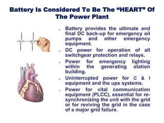
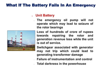
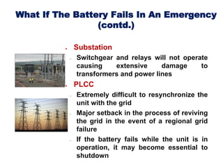
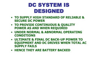
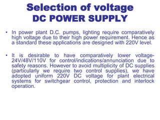
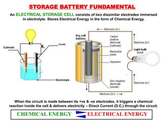
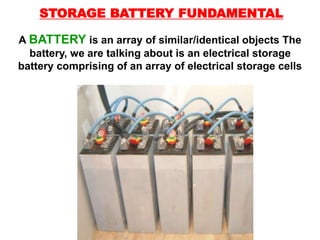
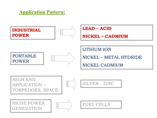
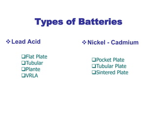
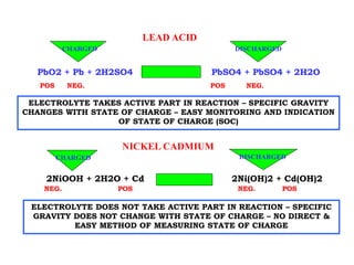
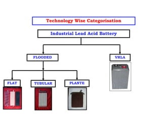
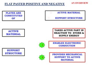
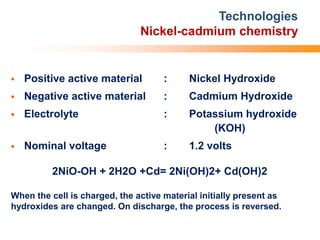
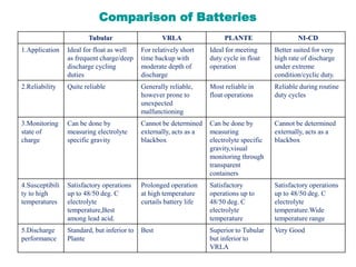
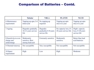
The document discusses batteries and DC power systems in power plants. It explains that batteries are critical as the "heart" of power plants, providing backup DC power for emergency equipment. If the battery fails, it can lead to major issues like seizure of turbine rotors, transformer damage, control failures, and blackouts. Proper DC system design is needed to provide reliable power under normal and abnormal conditions. The ultimate backup is the battery, which keeps critical equipment operational when both AC supply and diesel generators fail. The document then discusses different types of batteries used, including lead-acid, nickel-cadmium, and valve-regulated lead-acid (VRLA), explaining their characteristics, advantages, limitations and applications in power plants.


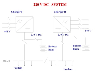
![DC SYSTEM
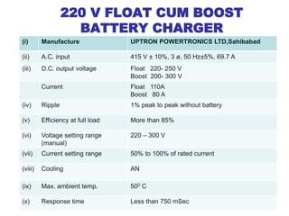
• BATTERY CHARGERS [TWO/THREE]
• BATTERY BANKS [ONE/TWO]
• DC DISTRIBUTION BOARDS [ONE/TWO]
• DC FUSE BOARDS
• UN EARTHED SYSTEM
• CHARGER TROUBLE, DC EARTH FAULT AND
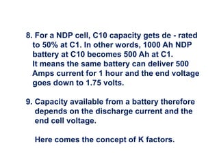
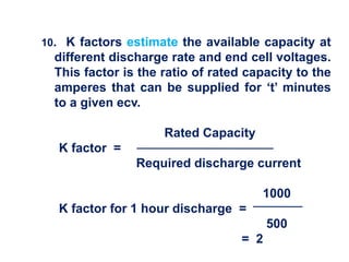
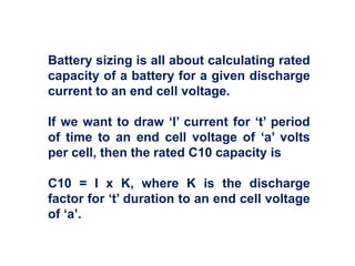
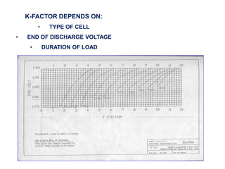
DC VOLTAGE ABNORMAL ALARMS IN UCB](https://image.slidesharecdn.com/dcsupplysystembatteriesups-copy-230708025210-e049c66b/85/DC-Supply-System-Batteries-UPS-Copy-pdf-90-320.jpg)