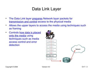
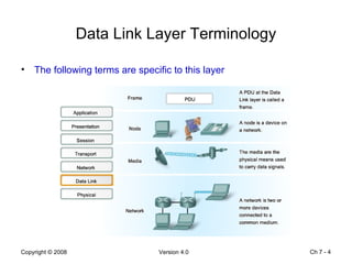
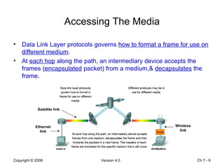
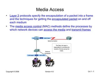
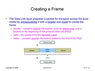
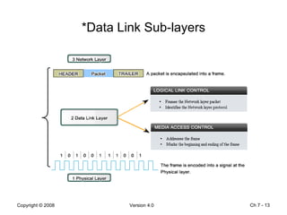
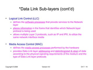
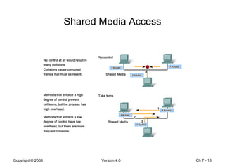
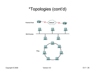
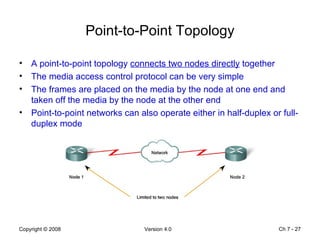
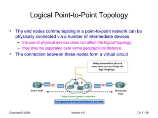
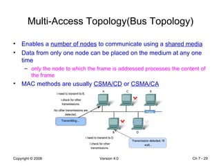
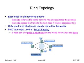
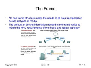
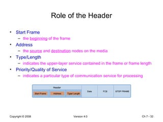
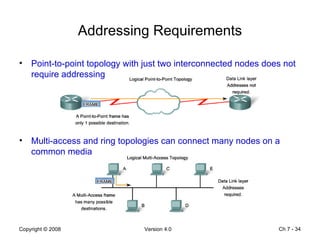
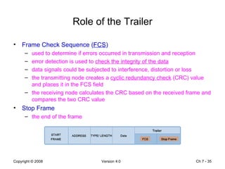
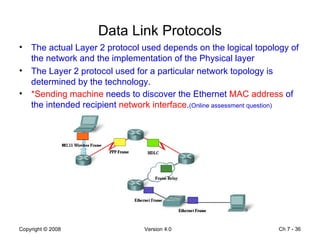
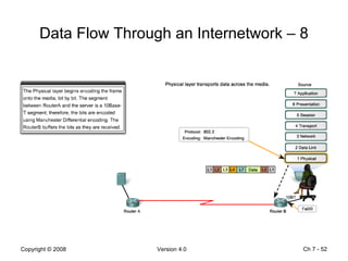
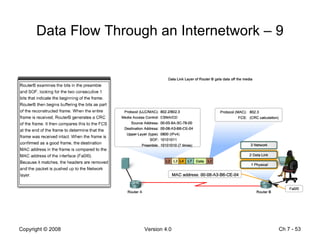
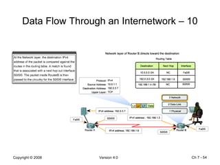
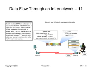
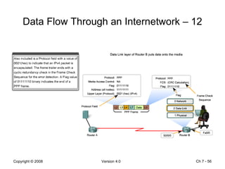
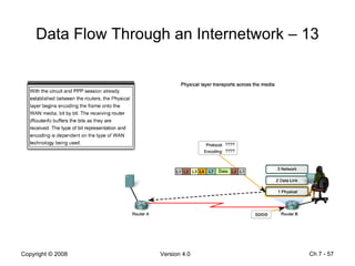
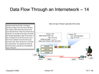
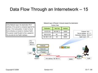
Ch 7 -  Chapter 7 Data Link Layer
Objectives Explain the  role of Data Link layer  protocols in data transmission  Describe how the Data Link layer prepares data for transmission on network media  Describe the different types of  media access control  methods  Identify several common  logical network topologies  and describe how the logical topology determines the media access control method for that network  Explain the  purpose  of  encapsulating packets into frames  to facilitate media access  Describe the Layer 2 frame structure and identify generic fields Explain the  role  of key frame  header  and  trailer  fields, including addressing, QoS, type of protocol and frame check sequence  Ch 7 -
Data Link Layer The Data Link layer  prepares  Network layer packets for  transmission and control  access to the physical media Allows the upper layers to access the media using techniques such as framing Ch 7 -  Controls  how data is placed onto the media  using techniques such as media access control and error detection
Data Link Layer Terminology The following terms are specific to this layer Ch 7 -
Network Types   Logical network defined at the Network layer by the arrangement of the hierarchical addressing scheme Physical network  represents the interconnection of devices on a common media also referred to as a network segment Ch 7 -
Accessing The Media Data Link Layer protocols governs  how to format a frame for use on different medium . At  each hop  along the path, an intermediary device accepts the frames ( encapsulated  packet) from a medium,&  decapsulates  the frame. Ch 7 -  Ethernet link Satellite link Wireless link
Media Access Layer 2  protocols specify the encapsulation of a packet into a frame and the techniques for getting the  encapsulated packet  on and off each medium  The  media access control  (MAC) methods define the processes by which network devices can  access the media  and  transmit frames Ch 7 -
Creating a Frame The Data Link layer prepares a packet for transport across the local media by  encapsulating  it with a  header  and  trailer  to create the frame header  – contains  control  information, such as  addressing , and is located at the beginning of the protocol data unit (PDU) data  – the packet from the  Network Layer trailer  – contains  control  information added to the end of the PDU Ch 7 -
Control Information Data Link layer protocols require control information to enable the protocols to function The control information performs the following function: which  nodes  are in communication with each other when communication between individual nodes begins and ends what  errors  occurred between the communicating nodes which nodes will communicate next Ch 7 -
Frame Structure Framing breaks the stream into decipherable groupings  control information is inserted in the header and trailer fields  The Bits signals the  start  and  stop  of the frame  Ch 7 -
Frame Fields Frame  start  and  stop   signal the beginning and end limits of a frame  Address  contains the address of the primary or secondary device  Type  the type of PDU contained in the frame  Quality control  establish, configure, maintain, and terminate the link Data  the frame payload, i.e. the Network layer packet Error detection   check the integrity of the frame Ch 7 -
Data Link Layer Function The Data Link layer is an interface between the  upper-layer  processes and the  Physical layer   connects the upper layer services to the media Usually implemented in the form of a network interface card Ch 7 -  contains  software  functions to prepare data for transmission and  encode  the data as signals to be sent on the media
*Data Link Sub-layers Ch 7 -
*Data Link Sub-layers (cont’d) Logical Link Control (LLC) defines the  software processes  that provide services to the Network layer  places information  in the frame that identifies which Network layer protocol is being used  allows multiple Layer 3 protocols, such as IP and IPX, to utilize the same network interface media Media Access Control (MAC) defines the  media access processes  performed by the hardware provides Data Link layer  addressing  and  delimiting(start & stop)  of data according to the physical signaling requirements of the medium and the type of Data Link layer protocols Ch 7 -
Data Link Layer Standards Data Link layer services and specifications are defined by multiple standards based on a variety of technologies and media  standards may integrate both Layers 1 and 2 services Ch 7 -
Shared Media Access Ch 7 -
Shared Media Access (cont’d) Regulating the  placement of data frames onto the media  is known as media access control (MAC) Data Link layer defines the rules for access to different media The * method of media access control  used depend on:  (Online assessment question) media sharing  – how the nodes share the media topology  – how the connection between the nodes appears to the Data Link layer Ch 7 -
*Controlled Access Network takes turn, in sequence, to access the medium known as scheduled access or  deterministic well-ordered and provides  predictable  output  can be inefficient because a device has to  wait for its turn  to use the media =>  No Collisions Ch 7 -
*Contention-Based Access Allows any device to access the medium whenever it has data to send also known as  non-deterministic no mechanism to track whose turn it is to access the media data collision occurs  when two or more devices access the media at the same time   Ch 7 -
Contention-Based Access (cont’d) Contention-based systems do not scale well under heavy media use the probability of successful media access without collision decreases as use and number of nodes increases  Recovery mechanisms needed to correct errors due to collisions further diminishes the throughput To prevent total chaos, a  Carrier Sense Multiple Access  (CSMA) process is used to detect if the media is carrying a signal  it is possible that the CSMA process will fail when two devices transmit at the same time –  data collision  CSMA is usually implemented in conjunction with either of the two methods for resolving media contention  CSMA/Collision Detection ( CSMA/CD )  CSMA/Collision Avoidance ( CSMA/CA )  Ch 7 -
*Carrier Sense Multiple Access CSMA/CD device monitors the media for the presence of a data signal  if a data signal is absent , the media is free and the device  transmits  the data if signals are detected, this indicates another device is transmitting and all other device must  stop sending  and  try again later this method is used by  802.3   Ethernet  networks CSMA/CA device examines the media, air, of the presence of a data signal device sends a notification,  Request to Send , across the media of its intent to use it device  then sends the data   this method is used by  802.11   wireless  networks Ch 7 -
Non-shared Media Access Require little or no control before placing frames onto the media The media connects two nodes in a point-to-point topology nodes do not have to share the media with other hosts Data Link protocols have little to do for controlling non-shared media access In point-to-point connections, the Data Link has to consider whether the communication is half-duplex or full-duplex Ch 7 -
Half-duplex Communication Half-duplex  communication means that the devices can both  transmit  and  receive  on the media but  NOT   simultaneously Arbitration rules for resolving conflicts are used to resolve conflicts such as more than one device attempts to transmit at the same time  Ch 7 -
Full-duplex Communication Both devices can  transmit  and  receive  on the media  simultaneously   the Data Link assumes the media is available for transmission   No media arbitration is necessary at the Data Link layer Ch 7 -
Topologies Physical  topology an arrangement of the nodes and the physical connections between them also called the cabled topology will most likely not be the same as the logical topology Logical  topology the way a network transfers frames from one node to the next consists of virtual connections between the nodes of a network independent of the physical layout  influences the type of  network framing and media access control used  Ch 7 -
*Topologies (cont’d) Ch 7 -
Point-to-Point Topology A point-to-point topology  connects two nodes directly  together The media access control protocol can be very simple The frames are placed on the media by the node at one end and taken off the media by the node at the other end Point-to-point networks can also operate either in half-duplex or full-duplex mode Ch 7 -
Logical Point-to-Point Topology The end nodes communicating in a point-to-point network can be physically connected via a number of intermediate devices the use of physical devices does not affect the logical topology they may be separated over some geographical distance The connection between these nodes form a virtual circuit  Ch 7 -
Multi-Access Topology(Bus Topology) Enables a  number of nodes  to communicate using a  shared media Data from only one node can be placed on the medium at any one time only the node to which the frame is addressed processes the content of the frame MAC methods are usually  CSMA/CD  or  CSMA/CA Ch 7 -
Ring Topology Each node in turn receives a frame the node removes the frame from the ring and examines the address the node passes the frame to the next node if it is not addressed to it Only one frame at a time is usually carried by the media MAC technique used is * Token Passing a node can only  place a data frame  on the media when it has the  token Ch 7 -
The Frame No one frame structure meets the needs of all data transportation across all types of media The amount of control information needed in the frame varies to match the MAC requirements of the media and logical topology Ch 7 -
Role of the Header Start Frame  the  beginning  of the frame Address  the  source  and  destination  nodes on the media Type/Length indicates the upper-layer service contained in the frame or frame length  Priority/Quality of Service indicates a particular type of communication service for processing  Ch 7 -
Physical Address Devices at the Data Link layer are referred to as  physical addresses   (MAC Address) Physical addresses do not indicate on what network the device is located  The physical address is used only for local delivery  the frame is used to transport data between nodes  the physical address has no meaning beyond the local network  Ch 7 -
Addressing Requirements Point-to-point topology with just two interconnected nodes does not require addressing Multi-access and ring topologies can connect many nodes on a common media Ch 7 -
Role of the Trailer Frame Check Sequence ( FCS ) used to determine if errors occurred in transmission and reception  error detection is used to  check the integrity of the data data signals could be subjected to interference, distortion or loss the transmitting node creates a  cyclic redundancy check  (CRC) value and places it in the FCS field the receiving node calculates the CRC based on the received frame and compares the two CRC value Stop Frame the end of the frame Ch 7 -
Data Link Protocols The actual Layer 2 protocol used depends on the logical topology of the network and the implementation of the Physical layer The Layer 2 protocol used for a particular network topology is determined by the technology. *Sending machine  needs to discover the Ethernet  MAC address  of the intended recipient  network interface . (Online assessment question) Ch 7 -
Technology LAN technology a LAN typically uses a  high-bandwidth  technology that is capable of supporting large number of users its high density of users within a relatively  small geographical  area makes this technology cost effective  WAN technology not cost effective to use a high-bandwidth technology over  large geographic  areas cost of the long distance physical links typically results in  lower bandwidth  capacity Ch 7 -
Ethernet Protocol Ethernet is a family of LAN networking technologies that are defined in the IEEE802.2 and 802.3 standards Ethernet standards define both the Layer 2 protocols and the Layer 1 technologies Ethernet is the most widely used LAN technology and supports data bandwidth of 10, 100, 1000 or 10,000 Mbps The basic frame format and the IEEE sub-layers of OSI Layers 1 and 2 remain consistent across all forms of Ethernet Ethernet uses unacknowledged  connectionless  service over a  shared  media using  CSMA/CD Ethernet II is the Ethernet frame format used in TCP/IP networks Ch 7 -
*Ethernet Protocol (cont’d) The Ethernet frame uses the media access control (MAC) address of the node as the Data Link layer address  *48-bit  MAC address (hexadecimal format) Ch 7 -
Point-to-Point Protocol (PPP) PPP is a  WAN protocol  used to deliver frames between  two nodes   PPP can be used on various physical media, including twisted pair, fiber optic and satellite transmission to accommodate the different types of media, PPP establishes logical connections, called sessions, between nodes The sessions also provide PPP with a method for  encapsulating  multiple protocols over a point-to-point link  each protocol encapsulated over the link establishes its own PPP session PPP also allows the two nodes to negotiate options within the PPP session  authentication ,  compression  and multilink (the use of multiple physical connections) Ch 7 -
Point-to-Point Protocol (cont’d) Figure shows the basic fields in a PPP frame Ch 7 -
Wireless Protocol  802.11 is an extension of the IEEE 802 protocol  uses the same 802.2 LLC and 48-bit addressing scheme as 802 LANs  commonly referred to Wi-Fi   contention-based system using CSMA/CA   supports authentication, association (connectivity to a wireless device) and privacy (encryption) CSMA/CA specifies a  random backoff  procedure for all nodes that are  waiting to transmit  medium contention is most likely just after the medium becomes available  making the nodes back off for a random period greatly reduces the likelihood of a collision  Ch 7 -
Wireless Protocol (cont’d) Figure shows the fields in an 802.11 frame  Ch 7 -
Communication Process The slides after this page shows the communication process between two hosts across an internetwork  In each step only the major elements are considered Read each explanation carefully and study the operation of the layers for each device  Ch 7 -
Data Flow Through an Internetwork – 1 Ch 7 -
Data Flow Through an Internetwork – 2  Ch 7 -
Data Flow Through an Internetwork – 3 Ch 7 -
Data Flow Through an Internetwork – 4 Ch 7 -
Data Flow Through an Internetwork – 5 Ch 7 -
Data Flow Through an Internetwork – 6 Ch 7 -
Data Flow Through an Internetwork – 7 Ch 7 -
Data Flow Through an Internetwork – 8 Ch 7 -
Data Flow Through an Internetwork – 9 Ch 7 -
Data Flow Through an Internetwork – 10 Ch 7 -
Data Flow Through an Internetwork – 11 Ch 7 -
Data Flow Through an Internetwork – 12 Ch 7 -
Data Flow Through an Internetwork – 13 Ch 7 -
Data Flow Through an Internetwork – 14 Ch 7 -
Data Flow Through an Internetwork – 15 Ch 7 -
Data Flow Through an Internetwork – 16 Ch 7 -
Data Flow Through an Internetwork – 17 Ch 7 -
Data Flow Through an Internetwork – 18 Ch 7 -
Data Flow Through an Internetwork – 19 Ch 7 -
Data Flow Through an Internetwork – 20 Ch 7 -
Data Flow Through an Internetwork – 21 Ch 7 -
Data Flow Through an Internetwork – 22 Ch 7 -

Chapter7

  • 1.
    Ch 7 - Chapter 7 Data Link Layer
  • 2.
    Objectives Explain the role of Data Link layer protocols in data transmission Describe how the Data Link layer prepares data for transmission on network media Describe the different types of media access control methods Identify several common logical network topologies and describe how the logical topology determines the media access control method for that network Explain the purpose of encapsulating packets into frames to facilitate media access Describe the Layer 2 frame structure and identify generic fields Explain the role of key frame header and trailer fields, including addressing, QoS, type of protocol and frame check sequence Ch 7 -
  • 3.
    Data Link LayerThe Data Link layer prepares Network layer packets for transmission and control access to the physical media Allows the upper layers to access the media using techniques such as framing Ch 7 - Controls how data is placed onto the media using techniques such as media access control and error detection
  • 4.
    Data Link LayerTerminology The following terms are specific to this layer Ch 7 -
  • 5.
    Network Types Logical network defined at the Network layer by the arrangement of the hierarchical addressing scheme Physical network represents the interconnection of devices on a common media also referred to as a network segment Ch 7 -
  • 6.
    Accessing The MediaData Link Layer protocols governs how to format a frame for use on different medium . At each hop along the path, an intermediary device accepts the frames ( encapsulated packet) from a medium,& decapsulates the frame. Ch 7 - Ethernet link Satellite link Wireless link
  • 7.
    Media Access Layer2 protocols specify the encapsulation of a packet into a frame and the techniques for getting the encapsulated packet on and off each medium The media access control (MAC) methods define the processes by which network devices can access the media and transmit frames Ch 7 -
  • 8.
    Creating a FrameThe Data Link layer prepares a packet for transport across the local media by encapsulating it with a header and trailer to create the frame header – contains control information, such as addressing , and is located at the beginning of the protocol data unit (PDU) data – the packet from the Network Layer trailer – contains control information added to the end of the PDU Ch 7 -
  • 9.
    Control Information DataLink layer protocols require control information to enable the protocols to function The control information performs the following function: which nodes are in communication with each other when communication between individual nodes begins and ends what errors occurred between the communicating nodes which nodes will communicate next Ch 7 -
  • 10.
    Frame Structure Framingbreaks the stream into decipherable groupings control information is inserted in the header and trailer fields The Bits signals the start and stop of the frame Ch 7 -
  • 11.
    Frame Fields Frame start and stop signal the beginning and end limits of a frame Address contains the address of the primary or secondary device Type the type of PDU contained in the frame Quality control establish, configure, maintain, and terminate the link Data the frame payload, i.e. the Network layer packet Error detection check the integrity of the frame Ch 7 -
  • 12.
    Data Link LayerFunction The Data Link layer is an interface between the upper-layer processes and the Physical layer connects the upper layer services to the media Usually implemented in the form of a network interface card Ch 7 - contains software functions to prepare data for transmission and encode the data as signals to be sent on the media
  • 13.
  • 14.
    *Data Link Sub-layers(cont’d) Logical Link Control (LLC) defines the software processes that provide services to the Network layer places information in the frame that identifies which Network layer protocol is being used allows multiple Layer 3 protocols, such as IP and IPX, to utilize the same network interface media Media Access Control (MAC) defines the media access processes performed by the hardware provides Data Link layer addressing and delimiting(start & stop) of data according to the physical signaling requirements of the medium and the type of Data Link layer protocols Ch 7 -
  • 15.
    Data Link LayerStandards Data Link layer services and specifications are defined by multiple standards based on a variety of technologies and media standards may integrate both Layers 1 and 2 services Ch 7 -
  • 16.
  • 17.
    Shared Media Access(cont’d) Regulating the placement of data frames onto the media is known as media access control (MAC) Data Link layer defines the rules for access to different media The * method of media access control used depend on: (Online assessment question) media sharing – how the nodes share the media topology – how the connection between the nodes appears to the Data Link layer Ch 7 -
  • 18.
    *Controlled Access Networktakes turn, in sequence, to access the medium known as scheduled access or deterministic well-ordered and provides predictable output can be inefficient because a device has to wait for its turn to use the media => No Collisions Ch 7 -
  • 19.
    *Contention-Based Access Allowsany device to access the medium whenever it has data to send also known as non-deterministic no mechanism to track whose turn it is to access the media data collision occurs when two or more devices access the media at the same time Ch 7 -
  • 20.
    Contention-Based Access (cont’d)Contention-based systems do not scale well under heavy media use the probability of successful media access without collision decreases as use and number of nodes increases Recovery mechanisms needed to correct errors due to collisions further diminishes the throughput To prevent total chaos, a Carrier Sense Multiple Access (CSMA) process is used to detect if the media is carrying a signal it is possible that the CSMA process will fail when two devices transmit at the same time – data collision CSMA is usually implemented in conjunction with either of the two methods for resolving media contention CSMA/Collision Detection ( CSMA/CD ) CSMA/Collision Avoidance ( CSMA/CA ) Ch 7 -
  • 21.
    *Carrier Sense MultipleAccess CSMA/CD device monitors the media for the presence of a data signal if a data signal is absent , the media is free and the device transmits the data if signals are detected, this indicates another device is transmitting and all other device must stop sending and try again later this method is used by 802.3 Ethernet networks CSMA/CA device examines the media, air, of the presence of a data signal device sends a notification, Request to Send , across the media of its intent to use it device then sends the data this method is used by 802.11 wireless networks Ch 7 -
  • 22.
    Non-shared Media AccessRequire little or no control before placing frames onto the media The media connects two nodes in a point-to-point topology nodes do not have to share the media with other hosts Data Link protocols have little to do for controlling non-shared media access In point-to-point connections, the Data Link has to consider whether the communication is half-duplex or full-duplex Ch 7 -
  • 23.
    Half-duplex Communication Half-duplex communication means that the devices can both transmit and receive on the media but NOT simultaneously Arbitration rules for resolving conflicts are used to resolve conflicts such as more than one device attempts to transmit at the same time Ch 7 -
  • 24.
    Full-duplex Communication Bothdevices can transmit and receive on the media simultaneously the Data Link assumes the media is available for transmission No media arbitration is necessary at the Data Link layer Ch 7 -
  • 25.
    Topologies Physical topology an arrangement of the nodes and the physical connections between them also called the cabled topology will most likely not be the same as the logical topology Logical topology the way a network transfers frames from one node to the next consists of virtual connections between the nodes of a network independent of the physical layout influences the type of network framing and media access control used Ch 7 -
  • 26.
  • 27.
    Point-to-Point Topology Apoint-to-point topology connects two nodes directly together The media access control protocol can be very simple The frames are placed on the media by the node at one end and taken off the media by the node at the other end Point-to-point networks can also operate either in half-duplex or full-duplex mode Ch 7 -
  • 28.
    Logical Point-to-Point TopologyThe end nodes communicating in a point-to-point network can be physically connected via a number of intermediate devices the use of physical devices does not affect the logical topology they may be separated over some geographical distance The connection between these nodes form a virtual circuit Ch 7 -
  • 29.
    Multi-Access Topology(Bus Topology)Enables a number of nodes to communicate using a shared media Data from only one node can be placed on the medium at any one time only the node to which the frame is addressed processes the content of the frame MAC methods are usually CSMA/CD or CSMA/CA Ch 7 -
  • 30.
    Ring Topology Eachnode in turn receives a frame the node removes the frame from the ring and examines the address the node passes the frame to the next node if it is not addressed to it Only one frame at a time is usually carried by the media MAC technique used is * Token Passing a node can only place a data frame on the media when it has the token Ch 7 -
  • 31.
    The Frame Noone frame structure meets the needs of all data transportation across all types of media The amount of control information needed in the frame varies to match the MAC requirements of the media and logical topology Ch 7 -
  • 32.
    Role of theHeader Start Frame the beginning of the frame Address the source and destination nodes on the media Type/Length indicates the upper-layer service contained in the frame or frame length Priority/Quality of Service indicates a particular type of communication service for processing Ch 7 -
  • 33.
    Physical Address Devicesat the Data Link layer are referred to as physical addresses (MAC Address) Physical addresses do not indicate on what network the device is located The physical address is used only for local delivery the frame is used to transport data between nodes the physical address has no meaning beyond the local network Ch 7 -
  • 34.
    Addressing Requirements Point-to-pointtopology with just two interconnected nodes does not require addressing Multi-access and ring topologies can connect many nodes on a common media Ch 7 -
  • 35.
    Role of theTrailer Frame Check Sequence ( FCS ) used to determine if errors occurred in transmission and reception error detection is used to check the integrity of the data data signals could be subjected to interference, distortion or loss the transmitting node creates a cyclic redundancy check (CRC) value and places it in the FCS field the receiving node calculates the CRC based on the received frame and compares the two CRC value Stop Frame the end of the frame Ch 7 -
  • 36.
    Data Link ProtocolsThe actual Layer 2 protocol used depends on the logical topology of the network and the implementation of the Physical layer The Layer 2 protocol used for a particular network topology is determined by the technology. *Sending machine needs to discover the Ethernet MAC address of the intended recipient network interface . (Online assessment question) Ch 7 -
  • 37.
    Technology LAN technologya LAN typically uses a high-bandwidth technology that is capable of supporting large number of users its high density of users within a relatively small geographical area makes this technology cost effective WAN technology not cost effective to use a high-bandwidth technology over large geographic areas cost of the long distance physical links typically results in lower bandwidth capacity Ch 7 -
  • 38.
    Ethernet Protocol Ethernetis a family of LAN networking technologies that are defined in the IEEE802.2 and 802.3 standards Ethernet standards define both the Layer 2 protocols and the Layer 1 technologies Ethernet is the most widely used LAN technology and supports data bandwidth of 10, 100, 1000 or 10,000 Mbps The basic frame format and the IEEE sub-layers of OSI Layers 1 and 2 remain consistent across all forms of Ethernet Ethernet uses unacknowledged connectionless service over a shared media using CSMA/CD Ethernet II is the Ethernet frame format used in TCP/IP networks Ch 7 -
  • 39.
    *Ethernet Protocol (cont’d)The Ethernet frame uses the media access control (MAC) address of the node as the Data Link layer address *48-bit MAC address (hexadecimal format) Ch 7 -
  • 40.
    Point-to-Point Protocol (PPP)PPP is a WAN protocol used to deliver frames between two nodes PPP can be used on various physical media, including twisted pair, fiber optic and satellite transmission to accommodate the different types of media, PPP establishes logical connections, called sessions, between nodes The sessions also provide PPP with a method for encapsulating multiple protocols over a point-to-point link each protocol encapsulated over the link establishes its own PPP session PPP also allows the two nodes to negotiate options within the PPP session authentication , compression and multilink (the use of multiple physical connections) Ch 7 -
  • 41.
    Point-to-Point Protocol (cont’d)Figure shows the basic fields in a PPP frame Ch 7 -
  • 42.
    Wireless Protocol 802.11 is an extension of the IEEE 802 protocol uses the same 802.2 LLC and 48-bit addressing scheme as 802 LANs commonly referred to Wi-Fi contention-based system using CSMA/CA supports authentication, association (connectivity to a wireless device) and privacy (encryption) CSMA/CA specifies a random backoff procedure for all nodes that are waiting to transmit medium contention is most likely just after the medium becomes available making the nodes back off for a random period greatly reduces the likelihood of a collision Ch 7 -
  • 43.
    Wireless Protocol (cont’d)Figure shows the fields in an 802.11 frame Ch 7 -
  • 44.
    Communication Process Theslides after this page shows the communication process between two hosts across an internetwork In each step only the major elements are considered Read each explanation carefully and study the operation of the layers for each device Ch 7 -
  • 45.
    Data Flow Throughan Internetwork – 1 Ch 7 -
  • 46.
    Data Flow Throughan Internetwork – 2 Ch 7 -
  • 47.
    Data Flow Throughan Internetwork – 3 Ch 7 -
  • 48.
    Data Flow Throughan Internetwork – 4 Ch 7 -
  • 49.
    Data Flow Throughan Internetwork – 5 Ch 7 -
  • 50.
    Data Flow Throughan Internetwork – 6 Ch 7 -
  • 51.
    Data Flow Throughan Internetwork – 7 Ch 7 -
  • 52.
    Data Flow Throughan Internetwork – 8 Ch 7 -
  • 53.
    Data Flow Throughan Internetwork – 9 Ch 7 -
  • 54.
    Data Flow Throughan Internetwork – 10 Ch 7 -
  • 55.
    Data Flow Throughan Internetwork – 11 Ch 7 -
  • 56.
    Data Flow Throughan Internetwork – 12 Ch 7 -
  • 57.
    Data Flow Throughan Internetwork – 13 Ch 7 -
  • 58.
    Data Flow Throughan Internetwork – 14 Ch 7 -
  • 59.
    Data Flow Throughan Internetwork – 15 Ch 7 -
  • 60.
    Data Flow Throughan Internetwork – 16 Ch 7 -
  • 61.
    Data Flow Throughan Internetwork – 17 Ch 7 -
  • 62.
    Data Flow Throughan Internetwork – 18 Ch 7 -
  • 63.
    Data Flow Throughan Internetwork – 19 Ch 7 -
  • 64.
    Data Flow Throughan Internetwork – 20 Ch 7 -
  • 65.
    Data Flow Throughan Internetwork – 21 Ch 7 -
  • 66.
    Data Flow Throughan Internetwork – 22 Ch 7 -

Editor's Notes

  • #2 This chapter introduces the general functions of the Data Link layer and the protocols associated with it.
  • #5 Media is the physical copper cable, optical fiber, or atmosphere through which the signals travel. A physical network is different from a logical network.
  • #6 Two fundamental concepts in networking are the difference between the logical and the physical network.
  • #7 At each hop along the path, an intermediary device accepts the frames (encapsulated packet) from a medium, decapsulates the frame, and then forwards the packets in a new frame appropriate to the medium of that segment of the physical network.
  • #9 Each frame type has three basic parts: header, data and trailer.
  • #14 The Data Link layer is often divided into two sub-layers.
  • #16 Data Link layer protocols are generally not defined by Request for Comments (RFCs). Although the Internet Engineering Task Force (IETF) maintains the functional protocols and services for the TCP/IP protocol suite in the upper layers, IETF does not define the functions and operation of that model's Network Access layer.
  • #26 The topology of a network is the arrangement or relationship of the network devices and the interconnections between them. Network topologies can be viewed at the physical level and the logical level.
  • #27 There are benefits to using a layered model to describe network protocols and operations.
  • #28 A physical point-to-point connection.
  • #29 A logical point-to-point connection between two nodes may not necessarily be between two physical nodes at each end of a single physical link.
  • #32 Each frame type has three basic parts: header, data and trailer.
  • #33 The field names above are non-specific fields listed as examples. Different Data Link layer protocols may use different fields from those mentioned.
  • #36 IPv6 features
  • #38 Technology is determined by the size of the network – in terms of the number of hosts and geographic scope – and the services provided by the network. Difference in bandwidth normally results in the use of different protocols for LANs and WANs.
  • #45 The following assumptions are made for this communication. All routing tables are converged ARP tables are complete A TCP session is already established between client and server DNS lookup for the www server is already cached at the client PPP has already established a physical circuit and has established a PPP session
  • #49 Consider an internetwork that requires three subnets.
  • #51 Consider this example with five LANs and a WAN for a total of 6 networks.