Download to read offline
![Q2. Determine the route to a destination network given that packets to
the remote network pass through two fast Ethernet ports. The delay of a
fast Ethernet port is 100MS
256 X
[
107/105 + 200/10
]
256X120
= 30720
Show IP route
C
192.168.1.0/24 is a directly connected Fast Ethernet 0/0
C
192.168.3.0/24 is a directly connected Fast Ethernet 0/1
D
192.168.2.0/24 [90/30720] via is a directly connected Fast
Ethernet 0/0
EIGRP
AA Metric = Administrative distance
a. Determine the dynamic routing protocol active on the router.
b. Sketch the network topology using the information in the table.
Label all network segments with their network address. Indicate
suitable IP addresses for all interfaces on connected networks.](https://image.slidesharecdn.com/networktechnology14jan2011-140221150238-phpapp01/75/Network-technology-Paper-2-5-2048.jpg)
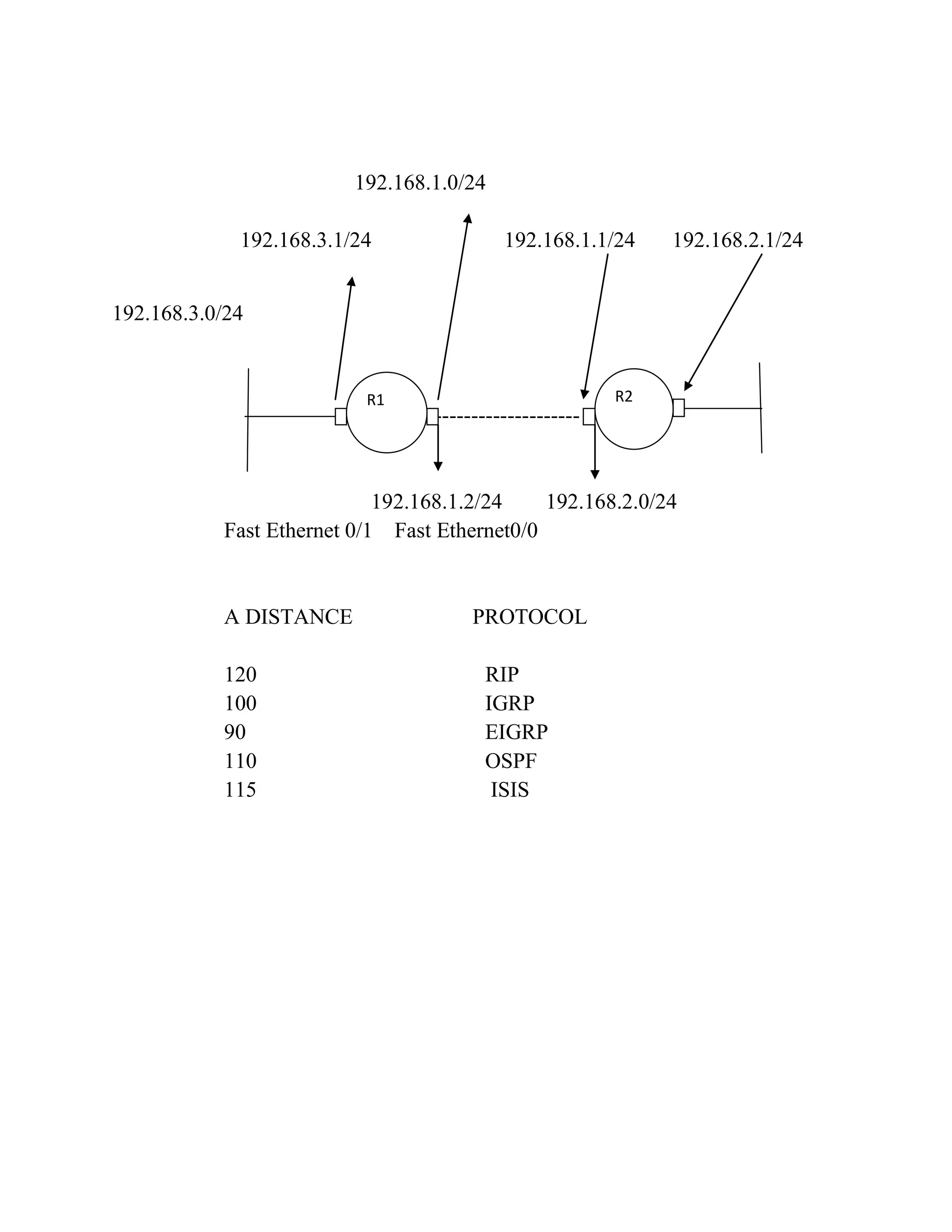
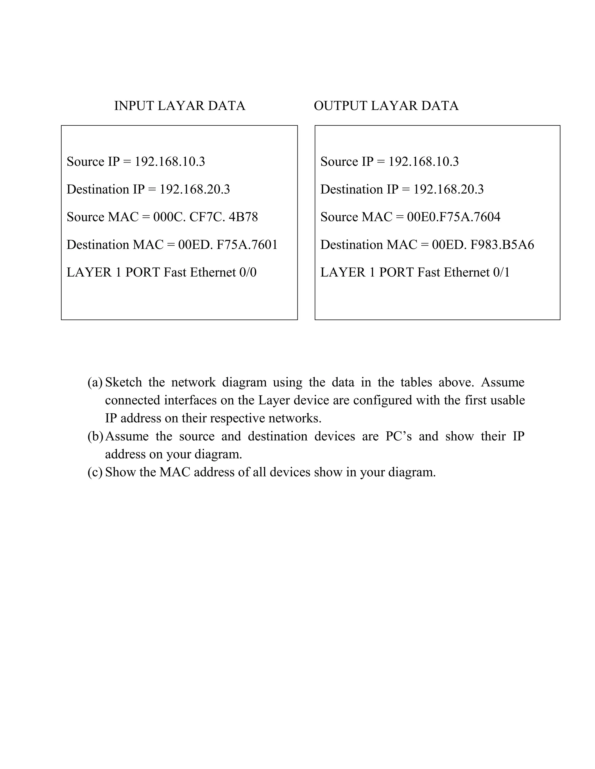
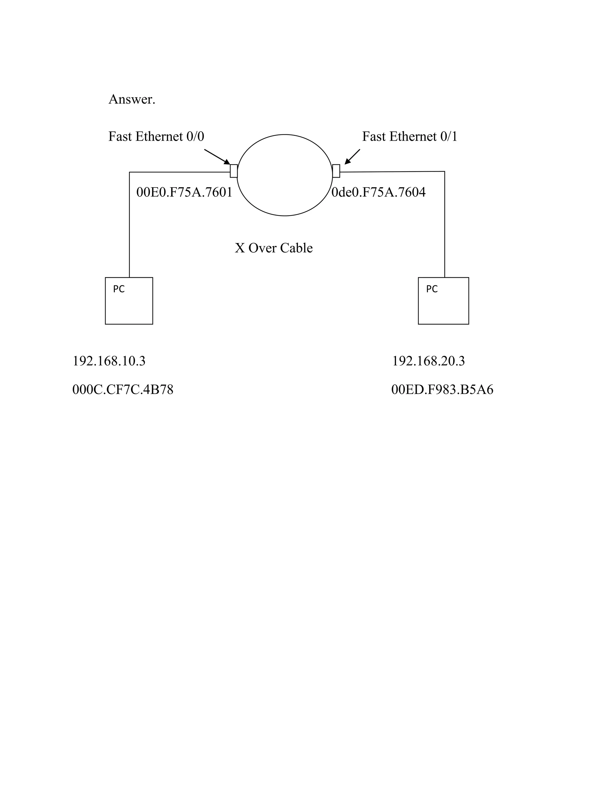

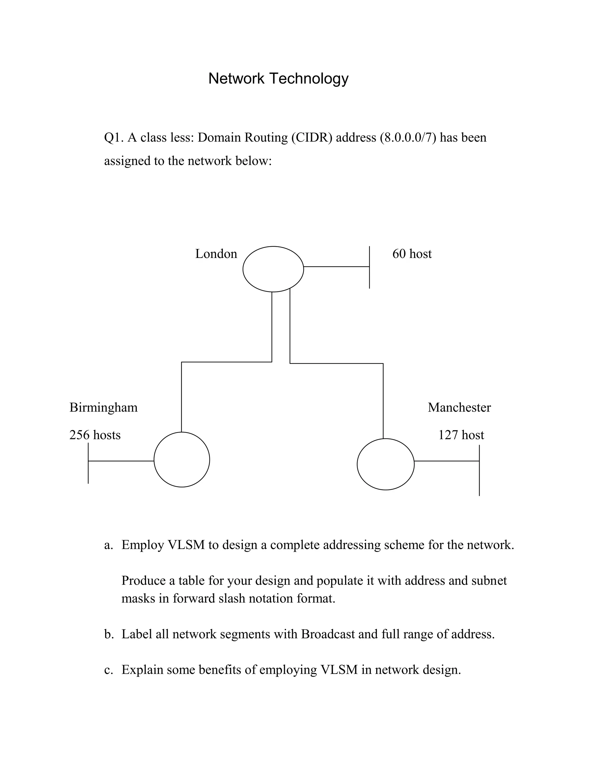
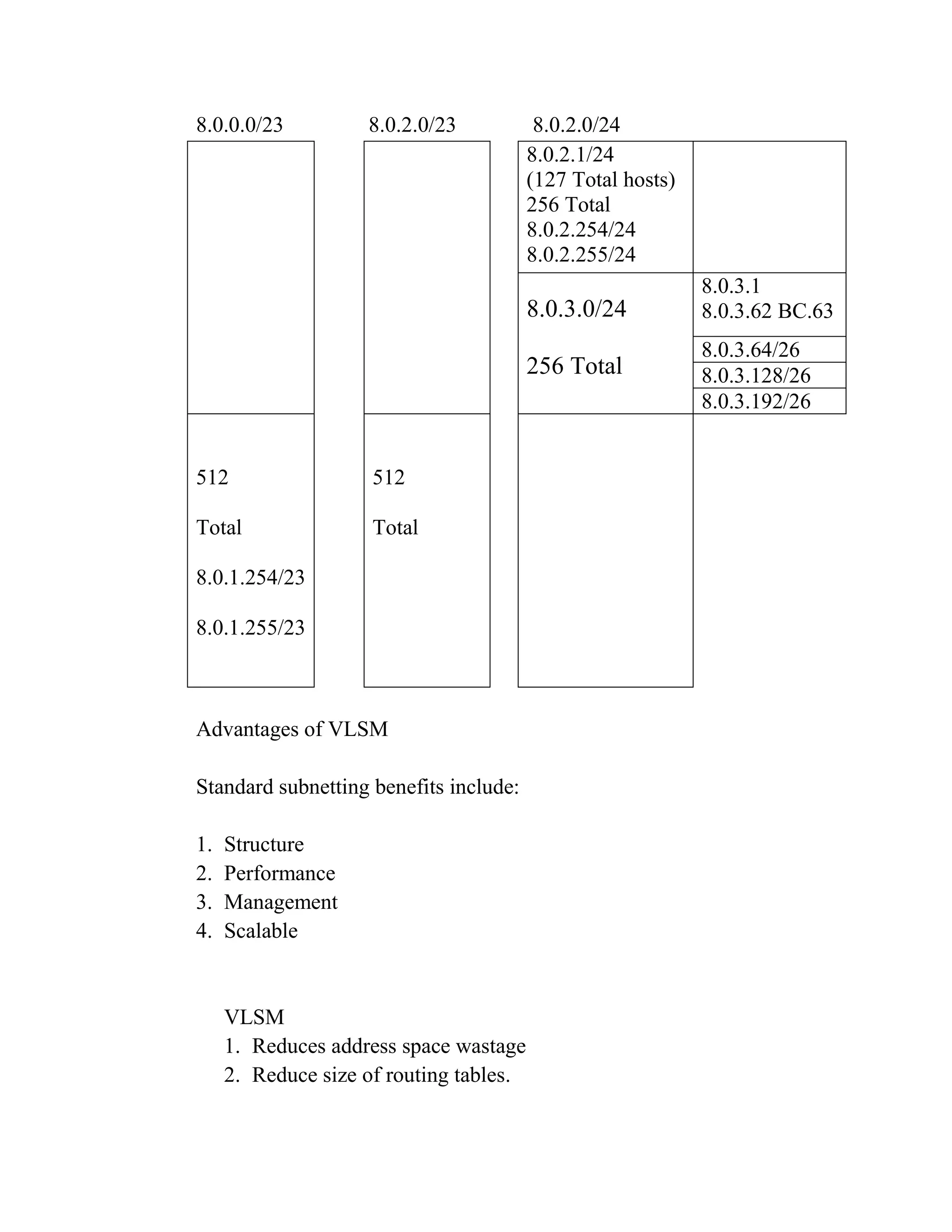
This document discusses network addressing and routing. It presents a network with three segments in London, Birmingham, and Manchester of varying host sizes. It asks the reader to: a) Design an addressing scheme using VLSM for the network and populate a table with subnets and masks b) Label the network segments with addresses and broadcasts c) Explain benefits of VLSM It then asks the reader to determine the routing protocol and sketch the topology for a network routing between two interfaces. Finally, it provides input/output layer data to sketch a network diagram showing IP addresses, MAC addresses, and interfaces between devices.