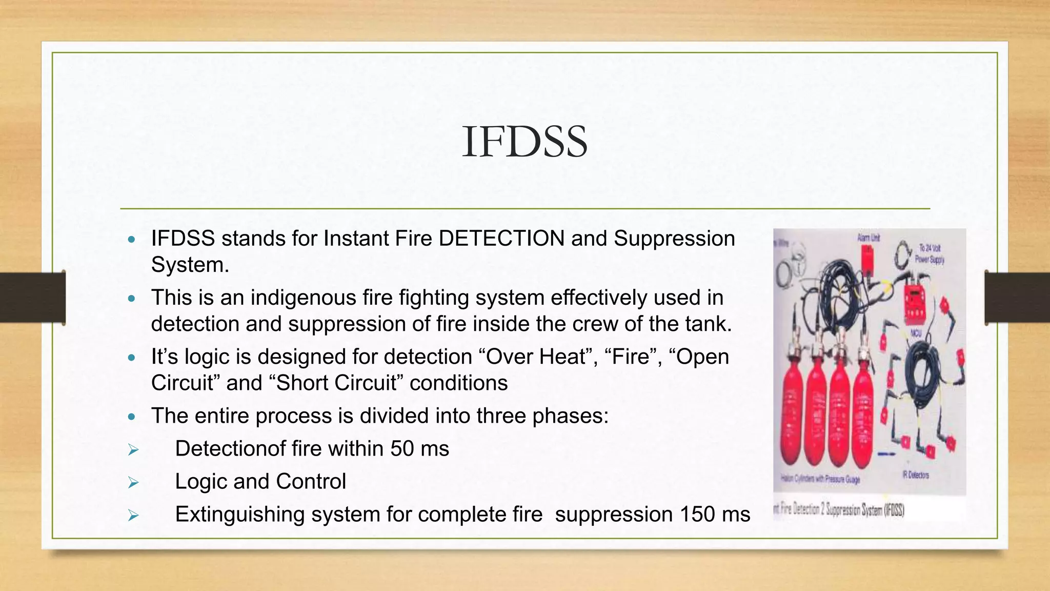
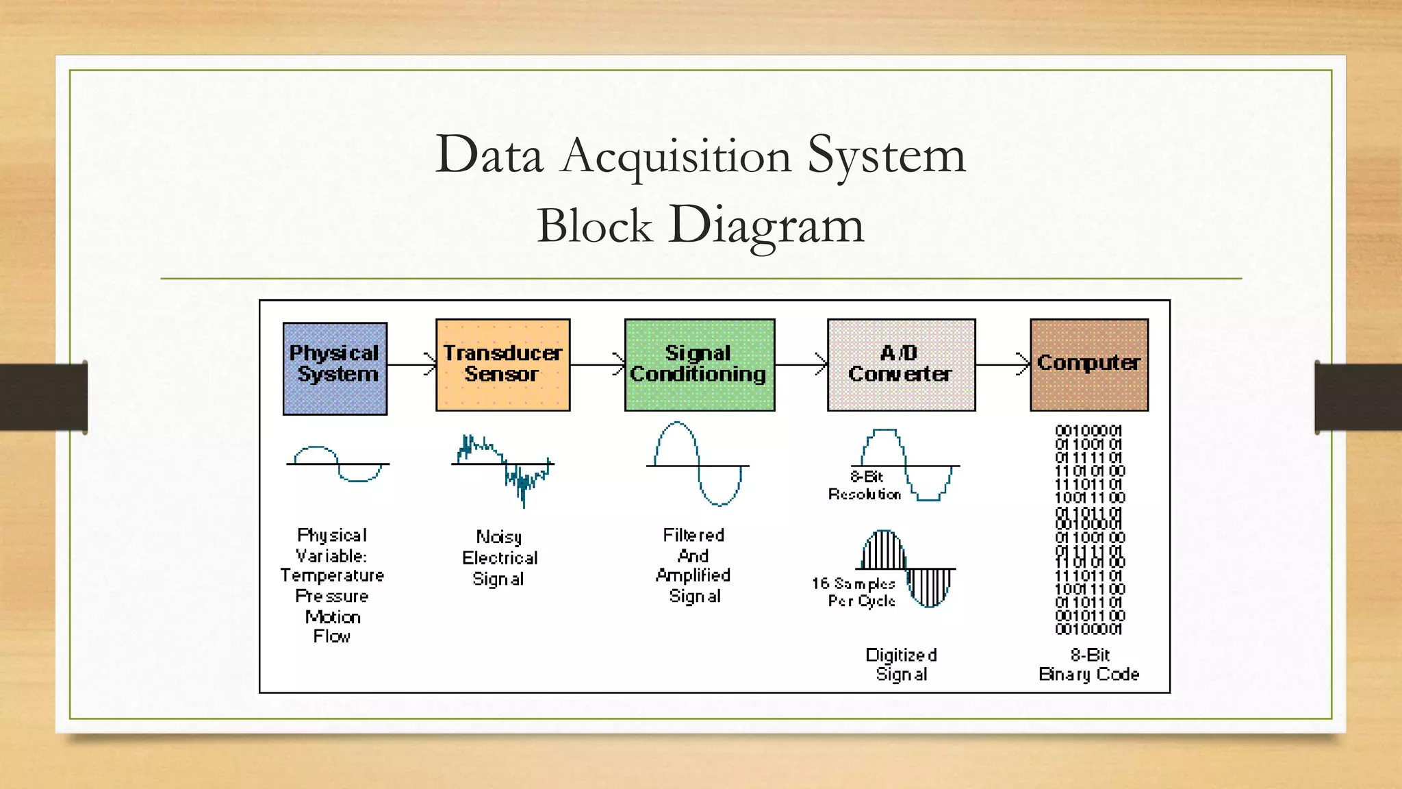
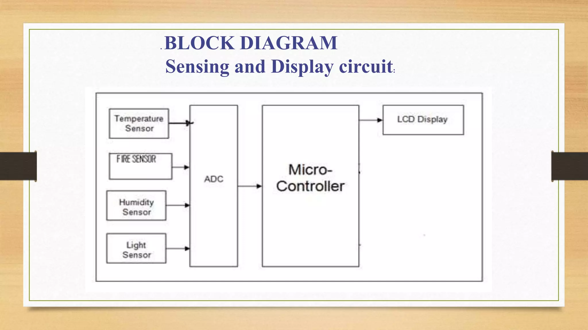
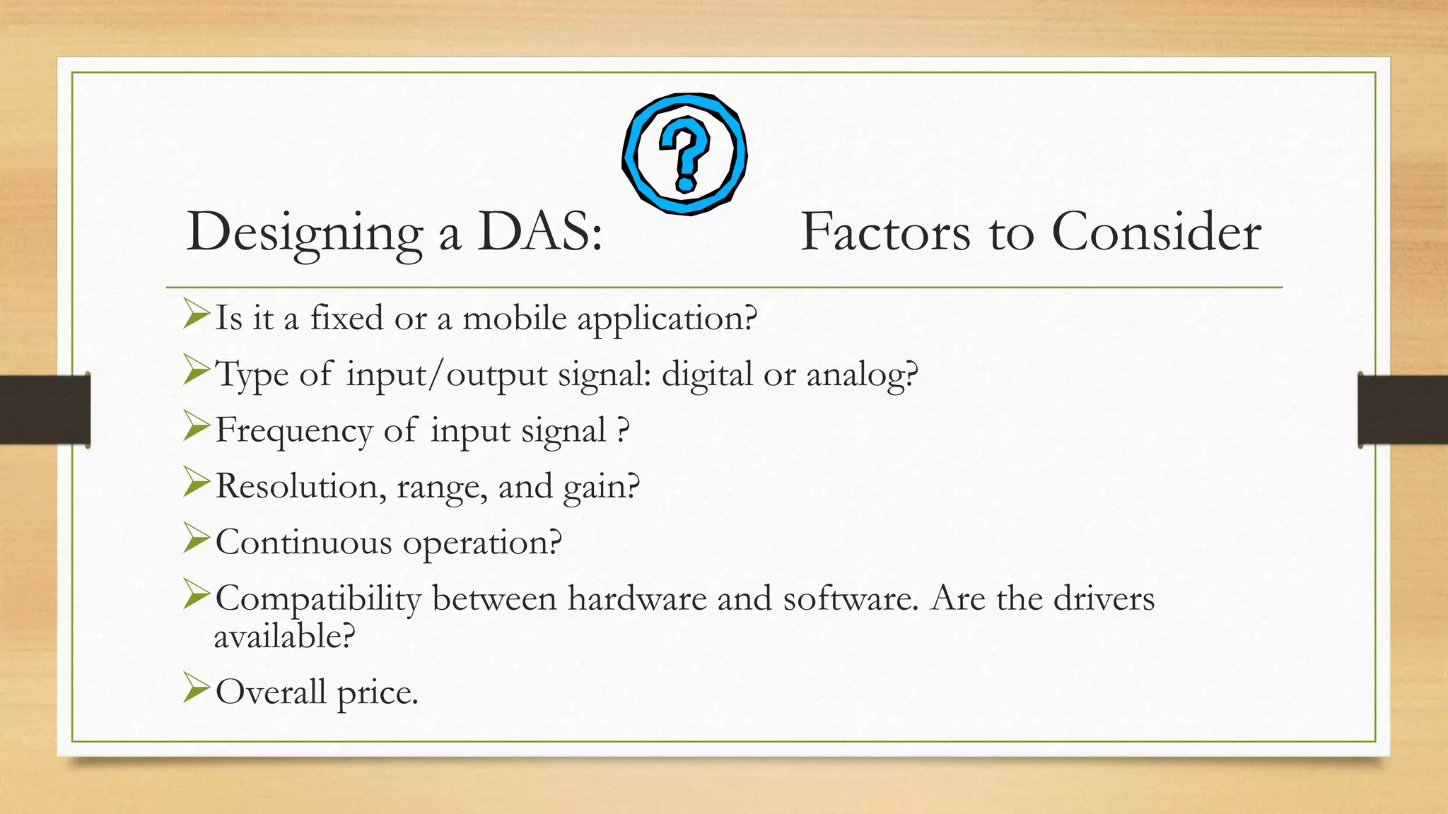
BY :
A M S SANTOSH
ROLL NO-04796402813
IFDSS
 IFDSS stands for Instant Fire DETECTION and Suppression
System.
 This is an indigenous fire fighting system effectively used in
detection and suppression of fire inside the crew of the tank.
 It’s logic is designed for detection “Over Heat”, “Fire”, “Open
Circuit” and “Short Circuit” conditions
 The entire process is divided into three phases:
 Detectionof fire within 50 ms
 Logic and Control
 Extinguishing system for complete fire suppression 150 ms
DATA ACQUISITION SYSTEM
• Data acquisition system is the process of sampling signals that measure real
world conditions and converting the resulting samples into digital numeric
values that can be manipulated by a computer.
• A DAQ system consists of sensors, DAQ measurement hardware and a
computer with programmable software.
Process in Data Acquisition System
A data acquisition system consists of many components that are integrated
to:
• Sense physical variables (use of transducers)
• Condition the electrical signal to make it readable by an A/D board
• Convert the signal into a digital format acceptable by a computer
• Process, analyze, store, and display the acquired data with the help of
software
Data Acquisition System
Block Diagram
Signal Conditioning
Electrical signals are conditioned so they can be used by an
analog input board. The following features may be available:
 Amplification Filtering
Linearization
Data Acquisition
• Data acquisition and control hardware generally performs one or
more of the following functions:
• analog input,
• analog output,
• digital input,
• digital output and
• counter/timer functions.
Analog Inputs (A/D)
• Analog to digital (A/D) conversion changes analog
voltage or current levels into digital information. The
conversion is necessary to enable the computer to
process or store the signals.
Analog Inputs (A/D)
• The most significant criteria when selecting A/D hardware are:
• 1. Number of input channels
• 2. Single-ended or differential input signals
• 3. Sampling rate (in samples per second)
• 4. Resolution (usually measured in bits of resolution)
• 5. Input range (specified in full-scale volts)
• 6. Noise and nonlinearity
A/D Converter:
Throughput
Effective rate of each individual channel is inversely proportional
to the number of channels sampled.
Example:
• 100 KHz maximum.
• 16 channels.
100 KHz/16 = 6.25 KHz per channel.
. LIST OF HARDWARE
•LM 35(Temperature sensor)
•Photo-diode
•Humidity sensor
•LDR(light sensor)
•ADC0848
•Microcontroller(AT89S52)
LCD(16x2)
Program burner
. BLOCK DIAGRAM
Sensing and Display circuit:
SENSORS INTERFACING WITH ADC0848
ADC INTERFACING WITH MICROCONTROLLER AT89S52
LCD INTERAFCE WITH MICRONTROLLER AT89S52
Sensing and display circuit
SOFTWARE DESIGNING
•Software is designed in C language.
•The C program is compiled in the compiler
• software ‘ KEIL’
• In this output of sensors from ADC is taken
through port 1 and then converted to displayable
digital form.
Programmable Software
• Involves the use of a programming language, such as:
• C++, visual C++
• Proteus for PCB designing
• BASIC, Visual Basic + Add-on tools (such as VisuaLab with VTX)
• Fortran
• Pascal
Advantage: flexibility
Disadvantages: complexity and steep learning curve
Designing a DAS: Factors to Consider
Is it a fixed or a mobile application?
Type of input/output signal: digital or analog?
Frequency of input signal ?
Resolution, range, and gain?
Continuous operation?
Compatibility between hardware and software. Are the drivers
available?
Overall price.
Data acquisition system

Data acquisition system

  • 1.
    BY : A MS SANTOSH ROLL NO-04796402813
  • 2.
    IFDSS  IFDSS standsfor Instant Fire DETECTION and Suppression System.  This is an indigenous fire fighting system effectively used in detection and suppression of fire inside the crew of the tank.  It’s logic is designed for detection “Over Heat”, “Fire”, “Open Circuit” and “Short Circuit” conditions  The entire process is divided into three phases:  Detectionof fire within 50 ms  Logic and Control  Extinguishing system for complete fire suppression 150 ms
  • 3.
    DATA ACQUISITION SYSTEM •Data acquisition system is the process of sampling signals that measure real world conditions and converting the resulting samples into digital numeric values that can be manipulated by a computer. • A DAQ system consists of sensors, DAQ measurement hardware and a computer with programmable software.
  • 4.
    Process in DataAcquisition System A data acquisition system consists of many components that are integrated to: • Sense physical variables (use of transducers) • Condition the electrical signal to make it readable by an A/D board • Convert the signal into a digital format acceptable by a computer • Process, analyze, store, and display the acquired data with the help of software
  • 5.
  • 6.
    Signal Conditioning Electrical signalsare conditioned so they can be used by an analog input board. The following features may be available:  Amplification Filtering Linearization
  • 7.
    Data Acquisition • Dataacquisition and control hardware generally performs one or more of the following functions: • analog input, • analog output, • digital input, • digital output and • counter/timer functions.
  • 8.
    Analog Inputs (A/D) •Analog to digital (A/D) conversion changes analog voltage or current levels into digital information. The conversion is necessary to enable the computer to process or store the signals.
  • 9.
    Analog Inputs (A/D) •The most significant criteria when selecting A/D hardware are: • 1. Number of input channels • 2. Single-ended or differential input signals • 3. Sampling rate (in samples per second) • 4. Resolution (usually measured in bits of resolution) • 5. Input range (specified in full-scale volts) • 6. Noise and nonlinearity
  • 10.
    A/D Converter: Throughput Effective rateof each individual channel is inversely proportional to the number of channels sampled. Example: • 100 KHz maximum. • 16 channels. 100 KHz/16 = 6.25 KHz per channel.
  • 11.
    . LIST OFHARDWARE •LM 35(Temperature sensor) •Photo-diode •Humidity sensor •LDR(light sensor) •ADC0848 •Microcontroller(AT89S52) LCD(16x2) Program burner
  • 12.
    . BLOCK DIAGRAM Sensingand Display circuit:
  • 14.
  • 15.
    ADC INTERFACING WITHMICROCONTROLLER AT89S52
  • 16.
    LCD INTERAFCE WITHMICRONTROLLER AT89S52
  • 17.
  • 18.
    SOFTWARE DESIGNING •Software isdesigned in C language. •The C program is compiled in the compiler • software ‘ KEIL’ • In this output of sensors from ADC is taken through port 1 and then converted to displayable digital form.
  • 19.
    Programmable Software • Involvesthe use of a programming language, such as: • C++, visual C++ • Proteus for PCB designing • BASIC, Visual Basic + Add-on tools (such as VisuaLab with VTX) • Fortran • Pascal Advantage: flexibility Disadvantages: complexity and steep learning curve
  • 20.
    Designing a DAS:Factors to Consider Is it a fixed or a mobile application? Type of input/output signal: digital or analog? Frequency of input signal ? Resolution, range, and gain? Continuous operation? Compatibility between hardware and software. Are the drivers available? Overall price.