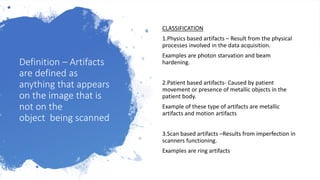
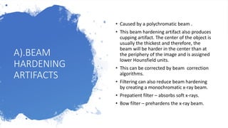
CT ARTIFACTS
Definition – Artifacts
are defined as
anything that appears
on the image that is
not on the
object being scanned
CLASSIFICATION
1.Physics based artifacts – Result from the physical
processes involved in the data acquisition.
Examples are photon starvation and beam
hardening.
2.Patient based artifacts- Caused by patient
movement or presence of metallic objects in the
patient body.
Example of these type of artifacts are metallic
artifacts and motion artifacts
3.Scan based artifacts –Results from imperfection in
scanners functioning.
Examples are ring artifacts
A).BEAM
HARDENING
ARTIFACTS
• Caused by a polychromatic beam .
• This beam hardening artifact also produces
cupping artifact. The center of the object is
usually the thickest and therefore, the
beam will be harder in the center than at
the periphery of the image and is assigned
lower Hounsfield units.
• This can be corrected by beam correction
algorithms.
• Filtering can also reduce beam hardening
by creating a monochromatic x-ray beam.
• Prepatient filter – absorbs soft x-rays.
• Bow filter – prehardens the x-ray beam.
B).METALLIC
ARTIFACTS.
Highly dense objects in
and around patient can
cause significant
streaking.
Appearance; Streaking
on the image.
• Remove metal objects.
• Decrease section width.
• Increase kVp for better penetrability.
• Adjust window level settings.
• Reorient data acquisition (e.g. gantry tilt)
• Metallic Artifact Reduction (MAR) software.
MAR uses interpolation to substitute over
range values in attenuation profiles.
Solutions:
C).PHOTON
STARVATION
• Parts of individual projections can be very
noisy due to insufficient photons passing
through the widest part of the patient.
• When these views are reconsructed,the
noise is magnified, resulting in streaks.
• Example is scan across the shoulders.
Smaller signals reach the detector, therefore
large proportion of noise.
• Solution :Adaptive filtering- the regions in
which the attenuation exceeds
a specified level are smoothed before
undergoing back projection .
• Milliampere (mA) modulation –higher mAs is
used for the more attenuation profile to
reduce the effect of photon starvation.
D).PARTIAL VOLUME ARTIFACTS.
• Partial volume effect occurs when two objects of different densities are occupying the same
plane.
• This may cause the object of interest to not fill the plane resulting in an underestimated
CT number.
• Partial volume artifacts occur when an off center object is occupying part of the scan plane.
• The inconsistences between views causes streaks.
• Solution : Use thinner slices.
E). RING ARTIFACTS.
• Ring artifacts occur due to malfunctioning of one or more of the
detectors in the array.
• Due to failure of a particular detector or miscalibration, incorrect
data in every projection will appear as a ring in the image.
• Solution : recalibrate the detectors.
• If rings persist even after recalibration ,call service.
F).CONE BEAM ARTIFACTS.
• Only in multi detector CT systems.
• As the section being scanned increases per rotation, a wider collimation is
used.
• Because of this the x-ray beam becomes cone shaped instead of fan shaped
and area imaged by each detector as it rotates around the patient is now a
volume instead of a flat plane .
• It appears as lines in windmill formation particularly at the edges of the
image.
• Solution :Use pitch selection recommended by the manufacturer. Most
modern scanner cone beam reconstruction algorithms correct this artifact.
G). TUBE ARCING
TUBE ARCING IS CAUSED BY A
TEMPORARY SHORT CIRCUIT IN THE
X-RAY TUBE CAUSING MOMENTARY
LOSS OF X-RAY OUTPUT.
IT IS SEEN ON THE IMAGE AS NEAR-
PARALLEL AND EQUIDISTANT STREAK
PATTERN ON TRANS AXIAL CT IMAGES
AND AS A HORIZONTAL HYPODENSE
BAND ON THE CORONAL AND SAGITTAL
CT IMAGES.
SOLUTION : CALL SERVICE.
H).STEP
ARTIFACTS
• Stair step artifacts occur around edges
of structures in three dimensional (3D)
and multi planar reconstruction (MPR)
images when wide collimations and
non-overlapping reconstruction
intervals are used.
• They are found in straight structures
which are oriented obliquely with
respect to movement of the table.
• Solution : Reduce collimation.
• Use overlapping reconstruction in
helical imaging.
• Thinner acquisition slices.
I).MOTION
ARTIFACTS.
• Motion artifacts are caused by the
voluntary or involuntary movement of the
patient during data acquisition.
• It appears as shading, streaking and
blurring.
• Solution : use shortest scan time as
possible.
• Immobilization aids.
• Consider sedation.
• Beta blockers for cardiac protocols.
• Special software correction which reduces
weighting of views obtained towards the
beginning and end of the scan.
J).OUT-OF-FIELD ARTIFACTS.
• These occur when a portion of the patient is outside the field of view (FOV).
• It is seen on the image as streaks.
• Common problem areas include shoulders, abdomen and lower pelvis.
• Solution : adjust patient position (L/R).
• Expand the FOV if possible.
K).SPIRAL INTERPOLATION ARTIFACTS.
• These are caused by images that are created from views that are not in the same plane.
• This results in inaccuracies in CT number.
• Appearance : streaks
• Solution : Lower pitch.
L).ALIASING ARTIFACTS
• Also known as under sampling.
• Refers to the error in the accuracy component of the ADC during image
digitization.
• When sampling, the brightness of each pixel in the image is measured and
creates an analog signal.
• The more the samples, the more accurate the representation of signal will
be,hence,if a lack of sampling has occurred the computer will process an
inaccurate image resulting in an aliasing artifact.
• Appearance : Fine lines.
• Solution :reduce pitch
• Acquiring the largest possible number of projections per rotation.(on some
scanners this can be achieved by using slower rotation speed)
M).EDGE GRADIENT EFFECT
• The edge gradient effect results in shading arising from irregularly
shaped objects that have different densities.
• Occurs when barium and air lie adjacent to each other in the
stomach .
• Appearance : straight lines radiating from high-contrast areas.
• Solution :Use thinner slices, Use low or neutral HU value oral contrast
in place Barium.
THANK YOU !!!!!!

Ct image artifacts

  • 1.
  • 2.
    Definition – Artifacts aredefined as anything that appears on the image that is not on the object being scanned CLASSIFICATION 1.Physics based artifacts – Result from the physical processes involved in the data acquisition. Examples are photon starvation and beam hardening. 2.Patient based artifacts- Caused by patient movement or presence of metallic objects in the patient body. Example of these type of artifacts are metallic artifacts and motion artifacts 3.Scan based artifacts –Results from imperfection in scanners functioning. Examples are ring artifacts
  • 3.
    A).BEAM HARDENING ARTIFACTS • Caused bya polychromatic beam . • This beam hardening artifact also produces cupping artifact. The center of the object is usually the thickest and therefore, the beam will be harder in the center than at the periphery of the image and is assigned lower Hounsfield units. • This can be corrected by beam correction algorithms. • Filtering can also reduce beam hardening by creating a monochromatic x-ray beam. • Prepatient filter – absorbs soft x-rays. • Bow filter – prehardens the x-ray beam.
  • 4.
    B).METALLIC ARTIFACTS. Highly dense objectsin and around patient can cause significant streaking. Appearance; Streaking on the image. • Remove metal objects. • Decrease section width. • Increase kVp for better penetrability. • Adjust window level settings. • Reorient data acquisition (e.g. gantry tilt) • Metallic Artifact Reduction (MAR) software. MAR uses interpolation to substitute over range values in attenuation profiles. Solutions:
  • 5.
    C).PHOTON STARVATION • Parts ofindividual projections can be very noisy due to insufficient photons passing through the widest part of the patient. • When these views are reconsructed,the noise is magnified, resulting in streaks. • Example is scan across the shoulders. Smaller signals reach the detector, therefore large proportion of noise. • Solution :Adaptive filtering- the regions in which the attenuation exceeds a specified level are smoothed before undergoing back projection . • Milliampere (mA) modulation –higher mAs is used for the more attenuation profile to reduce the effect of photon starvation.
  • 6.
    D).PARTIAL VOLUME ARTIFACTS. •Partial volume effect occurs when two objects of different densities are occupying the same plane. • This may cause the object of interest to not fill the plane resulting in an underestimated CT number. • Partial volume artifacts occur when an off center object is occupying part of the scan plane. • The inconsistences between views causes streaks. • Solution : Use thinner slices.
  • 7.
    E). RING ARTIFACTS. •Ring artifacts occur due to malfunctioning of one or more of the detectors in the array. • Due to failure of a particular detector or miscalibration, incorrect data in every projection will appear as a ring in the image. • Solution : recalibrate the detectors. • If rings persist even after recalibration ,call service.
  • 8.
    F).CONE BEAM ARTIFACTS. •Only in multi detector CT systems. • As the section being scanned increases per rotation, a wider collimation is used. • Because of this the x-ray beam becomes cone shaped instead of fan shaped and area imaged by each detector as it rotates around the patient is now a volume instead of a flat plane . • It appears as lines in windmill formation particularly at the edges of the image. • Solution :Use pitch selection recommended by the manufacturer. Most modern scanner cone beam reconstruction algorithms correct this artifact.
  • 9.
    G). TUBE ARCING TUBEARCING IS CAUSED BY A TEMPORARY SHORT CIRCUIT IN THE X-RAY TUBE CAUSING MOMENTARY LOSS OF X-RAY OUTPUT. IT IS SEEN ON THE IMAGE AS NEAR- PARALLEL AND EQUIDISTANT STREAK PATTERN ON TRANS AXIAL CT IMAGES AND AS A HORIZONTAL HYPODENSE BAND ON THE CORONAL AND SAGITTAL CT IMAGES. SOLUTION : CALL SERVICE.
  • 10.
    H).STEP ARTIFACTS • Stair stepartifacts occur around edges of structures in three dimensional (3D) and multi planar reconstruction (MPR) images when wide collimations and non-overlapping reconstruction intervals are used. • They are found in straight structures which are oriented obliquely with respect to movement of the table. • Solution : Reduce collimation. • Use overlapping reconstruction in helical imaging. • Thinner acquisition slices.
  • 11.
    I).MOTION ARTIFACTS. • Motion artifactsare caused by the voluntary or involuntary movement of the patient during data acquisition. • It appears as shading, streaking and blurring. • Solution : use shortest scan time as possible. • Immobilization aids. • Consider sedation. • Beta blockers for cardiac protocols. • Special software correction which reduces weighting of views obtained towards the beginning and end of the scan.
  • 12.
    J).OUT-OF-FIELD ARTIFACTS. • Theseoccur when a portion of the patient is outside the field of view (FOV). • It is seen on the image as streaks. • Common problem areas include shoulders, abdomen and lower pelvis. • Solution : adjust patient position (L/R). • Expand the FOV if possible. K).SPIRAL INTERPOLATION ARTIFACTS. • These are caused by images that are created from views that are not in the same plane. • This results in inaccuracies in CT number. • Appearance : streaks • Solution : Lower pitch.
  • 13.
    L).ALIASING ARTIFACTS • Alsoknown as under sampling. • Refers to the error in the accuracy component of the ADC during image digitization. • When sampling, the brightness of each pixel in the image is measured and creates an analog signal. • The more the samples, the more accurate the representation of signal will be,hence,if a lack of sampling has occurred the computer will process an inaccurate image resulting in an aliasing artifact. • Appearance : Fine lines. • Solution :reduce pitch • Acquiring the largest possible number of projections per rotation.(on some scanners this can be achieved by using slower rotation speed)
  • 14.
    M).EDGE GRADIENT EFFECT •The edge gradient effect results in shading arising from irregularly shaped objects that have different densities. • Occurs when barium and air lie adjacent to each other in the stomach . • Appearance : straight lines radiating from high-contrast areas. • Solution :Use thinner slices, Use low or neutral HU value oral contrast in place Barium.
  • 15.