There are many different types of CT artifacts, including noise, beam hardening, scatter, pseudoenhancement, motion, cone-beam, helical, ring and metal artifacts.
Artifacts
• Most artifactsin radiology refer to something seen on an image that are not present in
reality but appear due to a quirk of the modality itself. Artifact is also used to describe
findings that are due to things outside the patient that may obscure or distort the
image, e.g. clothing, external cardiac monitor leads, body parts of carer, etc.
• The commonest artifact seen in radiology is image noise, which is inherent to every
modality and technique, and can be mitigated but never eliminated.
• As an interpreter of imaging it is important to be aware of the main artifacts of the
examination being reviewed to avoid issuing an erroneous report. However at times
artifacts are welcome because they may be advantageous to the interpreter, making
anatomy/pathology easier to appreciate, e.g. posterior acoustic shadowing of
gallstones on ultrasound or susceptibility artifact of hemosiderin on MRI.
3.
CT artifacts
• CTartifacts are common and can occur for various
reasons. Knowledge of these artifacts is important
because they can mimic pathology (e.g. partial volume
artifact) or can degrade image quality to non-
diagnostic levels.
Physics-based artifacts
• beamhardening
• cupping artifact
• streak and dark bands
• metal artifact / high-density foreign material artifact
• partial volume averaging
• quantum mottle (noise)
• photon starvation
• aliasing
• truncation artifact
6.
Hardware-based artifacts
• ringartifact
• tube arcing
• out of field artifact
• air bubble artifact
• helical and multichannel artifact
• windmill artifact
• cone beam effect
• multiplanar reconstruction (MPR) artifact
• zebra artifact
• stair step artifact
7.
Motion artifact
• Motionartifact is a patient-based artifact that occurs with voluntary or involuntary
patient movement during image acquisition.
• Misregistration artifacts, which appear as blurring, streaking, or shading, are caused by
patient movement during a CT scan. Blurring also occurs with patient movement during
radiographic examinations.
• If patient movement is voluntary, patients may require immobilization or sedation to
prevent this.
• Involuntary motion, such as respiration or cardiac motion, may cause artifacts that
mimic pathology in surrounding structures.
• This artifact can be reduced by using a fast scanning technique. Techniques, such as
cardiac gating, may be used for examinations that concern the mediastinum.
Transient interruption of
contrast(TIC)
• Transient interruption of contrast (TIC) is a common flow artifact seen in
CT pulmonary angiography (CTPA) studies. The contrast opacification of the pulmonary
arteries is suboptimal due to an increase in the flow of unopacified blood from the
inferior vena cava (IVC) to the right side of the heart, often during deep inspiration.
Clothing artifacts
• Clothingartifacts, like jewelry artifacts, are a regular feature on imaging examinations,
especially plain radiographs, but in general are recognized for what they are, either at the
time the image is taken by the radiographer, or later by the reporting radiologist. The
radiographer will often either retake the image after the patient has removed the offending
garment, or more commonly they will label the image with a warning that clothing artifact is
present to avoid any misinterpretation taking place.
• Removing clothing that corresponds to the area of interest is important, in particular
digital image receptors are able to pick up even the stencils on t-shirts due to a higher
detective quantum efficiency compared to that of film. In the literature are good examples of
cases in which clothing has mimicked potentially more serious pathology 4,5
.
• Conversely, at least in mammography, it has been found that women keeping their brassieres
on improves dose-reduction techniques. The same study also showed that the metal
components of patients' bras did not have any adverse effect with regards to diagnostic
accuracy
jewelry artifacts
• tis common to see jewelry artifacts on imaging examinations, most commonly plain radiographs, although also on other
modalities, where they can produce unhelpful artifacts that may obscure important structures and preclude confident
diagnostic evaluation 1
.
• These include:
• body piercings in many different anatomical locations
• most commonly earrings
• nose studs/rings
• nipple rings
• cleavage rings
• umbilical rings
• genital rings
• also tongue, lips, eyebrows, chin, etc.
• necklaces, bracelets, anklets, chains etc.
• finger and - much more rarely - toe rings
• It is therefore incumbent upon the patient to remove jewelry before an imaging examination if it is likely to create
diagnostic confusion. Usually, the radiographer will request that a patient removes all jewelry before imaging is performed.
Physics-based artifacts
beam hardening
•Beam hardening is the phenomenon that occurs when an x-ray beam
comprised of polychromatic energies passes through an object, resulting in
selective attenuation of lower energy photons. The effect is conceptually similar
to a high-pass filter in that only higher energy photons are left to contribute to
the beam, and thus, the mean beam energy is increased ("hardened") .
• This same phenomenon is exploited in radiography and CT by the use of metal
filters to "pre-harden" the x-ray spectrum and minimize low-energy photons (see
filters) .
• In CT, beam hardening from a very dense target (e.g. bone or iodinated
contrast) may result in characteristic artifacts. CT beam hardening artifacts have
two distinct manifestations: streaking (dark bands) and cupping artifacts.
Beam hardening reduction
•Most modern CT scanners utilize filters in an attempt to overcome beam hardening. An
attenuating substance (usually metallic) is often appropriated to harden the beam
before it reaches the patient.
• CT scanners must often be calibrated with vendor-specific phantoms to overcome
unavoidable beam hardening artifacts such as cupping.
• Streak artifacts can sometimes be effectively reduced by increasing tube voltage
(better penetration of high-density objects) or using a dual-energy imaging approach.
Many modern scanners are also equipped with metal artifact reduction algorithms that
utilize iterative reconstruction to limit beam hardening artifacts.
19.
Streaking artifact
• Thestreaking artifact appears as multiple dark
streaking bands positioned between two dense
objects, for example, at the posterior fossa.
Streaking may also occur along the long axis of a
single high-attenuation object.
• It is the result of the polychromatic x-ray being
‘hardened’ at different rates according to the
rotational position of the tube/detector.
20.
Cupping artifact
• Beamhardening will cause the middle of the image to decrease in
value, not increase edge value, as the lower energy photons
preferentially get attenuated over longer path lengths. As the beam
becomes harder and passes a higher mean beam energy, the
lower attenuation coefficient means the CT number goes down for
longer paths.
• If uncorrected during CT reconstruction, these differences in the
expected attenuation profile lead to a perceived peripheral dense
appearance.
• Since simple beam hardening correction is built into modern
scanners, the cupping artifact is not usually encountered during
clinical imaging. The characteristic "cupped shaped profile" of the
CT numbers is best demonstrated when scanning phantoms
21.
Partial volume artifact
•occurs when tissues of widely different absorption are encompassed on the same CT
voxel producing a beam attenuation proportional to the average value of these
tissues.
• The latest generation of CT scanners with an associated reduction in the volume of a
voxel has substantially reduced the occurrence of this artifact.
• Partial volume averaging is particularly problematic in CT angiography (e.g.
misdiagnosis of an apparent contrast filling defect caused by the artifact as PE).
Therefore the use of thin section reconstructions (1-1.5 mm) are recommended where
the impact of this artifact is not negligible
Quantum Mottle (Noise)
•Noise, variability that is not part of a desired signal, is
present in all electronic systems, and originates from a
number of sources including electronic interference.
• It appears as an irregular granular pattern in all images
and degrades image information.
• It may be inapparent or render images non-diagnostic,
depending on the severity.
• Noise should not be confused with other artifacts, which
are less random and should be repeatable in theory,
although noise is itself an artifact.
24.
Noise in computedtomography
• Noise in computed tomography is an unwanted change in pixel values in an otherwise
homogeneous image. Often noise is defined loosely as the grainy appearance on
cross-sectional imaging; more often than not, this is quantum mottle.
• Noise in CT is measured via the signal to noise ratio (SNR); comparing the level of
desired signal (photons) to the level of background noise (pixels deviating from
normal). The higher the ratio, the less noise is present in the image.
• Noise in a cross-sectional image will equal a decrease in the picture quality and
inadvertently will hinder the contrast resolution.
25.
Factors affecting noise
•mAs
• The mAs or the dose of a CT scan has a direct relationship with the number of photons
utilized in the examination. A useful relationship to keep in mind is:
• 2 x mAs = 40% increase SNR
• Increasing the dose of the scan will decrease the amount of noise and hence improve
the contrast resolution of the image. However it comes at a cost, and balancing the
dose with the contrast resolution required for interpretation must be considered when
determining examination settings.
• Studies that rely on superior contrast resolution will inescapably require a higher dose
than examinations that can tolerate a higher amount of noise, for example, liver
imaging vs cardiac calcium scores.
26.
Slice thickness
• Thenumber of photons available to generate an image has a linear relationship to the
slice thickness. The thicker the slice, the more photons available; and the more photons
available, the better the SNR. However, this is not without a trade-off because
increasing the slice thickness will decrease the spatial resolution in the z-axis.
27.
•Patient size
• Largerpatients will absorb more radiation than smaller ones, meaning fewer
photons will reach the detector hence reducing the signal to noise ratio.
•Reconstruction algorithm
• Non-linear reconstruction algorithms can cause noise non-uniformity, meaning
the intensity of noise varies across the image depending on regional structure.
Uniform regions of the image will generally have lower noise levels than highly
structured regions.
28.
•Noise metrics
• Avariety of metrics are used to measure different qualities of CT noise. Noise has many
aspects including magnitude, texture, and nonuniformity.
•Magnitude
• Noise magnitude is quantified simply by the standard deviation. CT noise magnitude
makes up the denominator of the signal to noise ratio.
•Texture
• Noise texture is the visual impression or quality of noise. It can be measured
quantitatively by computing the noise power spectrum.
•Non-uniformity
• Noise non-uniformity is caused by variation in noise magnitude or texture across the
image.
29.
Photon starvation
• Photonstarvation is one source of streak artifact which may occur in CT. It is seen in
high attenuation areas, particularly behind metal implants. Because of high
attenuation, insufficient photons reach the detector. During the reconstruction process,
the noise is greatly magnified in these areas leading to characteristic streaks in the
image 3
.
• In some applications, namely low dose CT protocols, the increased noise due to photon
starvation is normally encountered as a trade-off between low patient radiation dose
and acceptable image quality. The artifact can be reduced by automatic
tube current modulation (increased mAs) and adaptive filtration via applying the local
filter. Use of iterative reconstruction techniques can also significantly reduce image
noise caused by this artifact
Aliasing artifact
• Aliasingartifact, otherwise known as undersampling, in CT refers to an error in the
accuracy proponent of analog to digital converter (ADC) during image digitization.
• Image digitization has three distinct steps: scanning, sampling, and quantization.
• When sampling, the brightness of each pixel in the image is measured, and via a
photomultiplier, creates an output analog signal that is then due to undergo
quantization.
• The more samples that are taken the more accurate the representation of the signal
will be, hence if a lack of sampling has occurred the computer will process an
inaccurate image resulting in an aliasing artifact.
• The artifact has the appearance of Moiré patterns.
Moiré fringes /Patterns
•Moiré fringes are an interference pattern most commonly seen when acquiring gradient echo
images using the body coil.
• Because of the lack of perfect homogeneity of the main magnetic field from one side of the
body to the other, aliasing of one side of the body to the other results in the superimposition of
signals of different phases that alternatively add and cancel, this causes the banding
appearance similar to the effect of looking through two screen windows or through the railings
of bridge from distance.
• Shimming will help to reduce this artifact by making the magnetic field more homogeneous .
The term Moiré when used in digital imaging and computer graphics describes an artefact
that can be created by overlaying two semi-transparent grids or repeating line patterns on
each other, which creates an interference pattern. In general radiography, the term has been
used to describe the 'grid moiré pattern' where there is under sampling due to incorrect grid
placement or alignment
Truncation artifact
• Truncationartifact in CT is an apparently increased curvilinear band
of attenuation along the edge of the image.
• This artifact is encountered when parts of the imaged body part
remain outside the field of view (e.g. due to patient body habitus),
which results in inaccurate measurement of attenuation along the
edge of the image.
• The artifact can be reduced - if possible - by using an extended
FOV reconstruction of the affected region
36.
Hardware-based artifacts
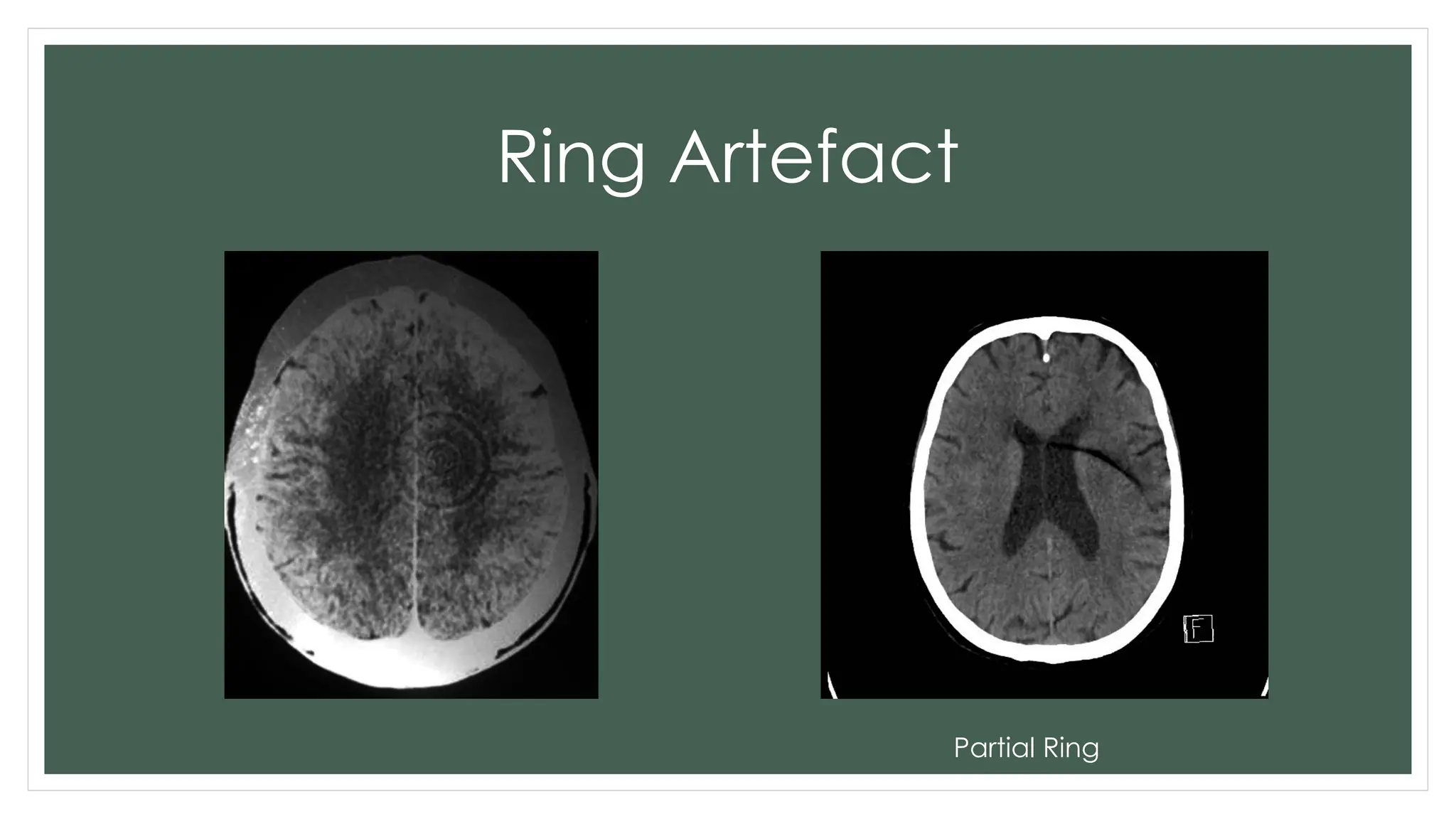
Ring artifacts
•Ring artifacts are a CT phenomenon that occurs due to the miscalibration or failure of one or more detector
elements in a CT scanner. Less often, it can be caused by insufficient radiation dose or contrast material
contamination of the detector cover 2
. One should be aware of this artifact as it can be misinterpreted as
pathology if goes unchecked.
• Features
• This artifact usually occurs in 3rd generation CT machines because the detector row rotates around the
patient. Miscaliberation of one detector will give erroneous readings around the patient as the detector
moves, thus giving a circular artifact 1
.
• However, ring artifacts seen in phantom may not be seen in clinical images because a wide window is
used 1
.
• They occur close to the isocenter of the scan and are usually visible on multiple slices at the same location.
They are a common problem in cranial CT.
Solutions
• Selecting thecorrect scan field using calibration data that are more closely fit with the
anatomy of the patient may reduce artifact.
• Recalibration or repair of the detector will usually rectify the artifact. Occasionally
detector elements need replacing, which can be costly. The referring clinician should
be notified that the concerning ring shadows are artifactual.
39.
Tube arcing
• Tubearcing occurs when there is a short-circuit within the tube,
typically from the cathode to the tube envelope. The result is a
temporary loss of x-ray output and a localized artifact.
• A number of causes of tube arcing are recognized :
insulator surface flashover
insulator breakdown
vacuum flashover
most common
due to particulate impurities or gas within the tube
new tubes are more prone to this problem due to residual gas
• A small amount of tube arching is not uncommon and modern
scanners have automated processes to remove the artifact from
the final images
40.
Out of fieldartifact/ incomplete
projection artifact
• Out of field artifact, also known as incomplete projection artifact, is due to part of the
patient existing peripheral to the field of view of the CT scanner. This can be a
particular issue in obese patients who only just fit within the scanner bore.
• The lack of data from these out of field tissue/objects interferes with the ability of the
software to generate a correct image leading to streaking, and areas of unusual
increased or decreased density. At best this is a mere annoyance, at worst it may
render the images uninterpretable.
• A contributing factor, especially in obese patients, may be the obstruction of reference
channels of the x-ray detectors, which can also produce streaking artifact.
• Preventing this artifact relies on the CT operator ensuring that the body of the patient
lies wholly within the scan field or - in the case of the arms - place them up or down
depending upon whether the head and neck or chest and body are being scanned.
Air bubble artifact
•The air bubble artifact is a CT artifact that manifests from the presence of abnormal gas
in the oil coolant which surrounds the x-ray tube. The artifact manifests as subtle low
density, which has only been described on brain scans.
• Cause
• The x-ray tube in a CT scanner is prevented from overheating by a heat exchange
system which uses oil as its coolant. The abnormal bubbles of air/gas in the system
subtly modify the transmission of the primary x-ray beam, decreasing its attenuation by
up to 3 HU. The number and precise location of the bubbles may vary over time - due
to their movement in the coolant - so that fluctuating attenuation of the x-rays occurs
as coolant circulates and the tube rotates. Therefore the position and severity of the
artifact also varies. As the effect on the attenuation of the x-ray beam is very mild this
artifact has only been seen when narrow window widths are used, which for practical
purposes is solely CT brain studies, primarily on "stroke" window settings.
Formation of airbubbles
• Gas/air bubbles can arise within the coolant oil via several different mechanisms 3
:
• during CT service/repair, e.g. oil changes/top-ups
• loss of integrity of the tube envelope/heat exchanger: it is designed to be a self-
contained unit with no communication with the external environment
• spontaneous formation of gas within the oil when in situ, due to vaporization in the
system, increasingly common as the tube ages
45.
Removing the artifact
•Resolving the artifact requires an engineer to replace the oil and
treat any underlying defect in the system e.g. a leak in the tube
housing.
46.
Helical and multichannelartifact
windmill artifact
• In CT imaging, the windmill artifact is an image distortion in the axial
plane, encountered during helical multidetector acquisitions. The telltale appearance
is characterized by equally distanced bright streaks diverging from a focal high-density
structure. The streaks seemingly rotate while scrolling back and forth through the
affected slices - hence the name 1
.
• The windmill artifact is caused by inadequate data sampling in the z-plane, due to
multiple detector rows intersecting the reconstruction plane during each rotation of the
gantry. With increasing helical pitch, the number of detector rows intersecting the same
image plane also increases, thus resulting in an increased amount of streaks 2
. The
windmill artifact can be therefore ameliorated by either decreasing the pitch or using
axial acquisition technique instead.
Pitch (P)
• Pitch(P) is a term used in helical CT with two terminologies depending on whether
single slice or multislice CT scanners are used 1-3
.
• Single slice CT (SSCT)
• The term detector pitch is the table distance traveled in one 360° gantry rotation
divided by beam collimation 2
.
• For example, if the table traveled 5 mm in one rotation and the beam collimation was 5
mm, then pitch equals 5 mm / 5 mm = 1.0.
49.
Choice of pitchaffects both
image quality and patient dose :
• P = 1.0: x-ray beams are contiguous for adjacent rotations
• P >1.0: x-ray beams are not contiguous for adjacent rotations; i.e. there are gaps in the
x-ray helix, but the full volume is still irradiated, only with fewer projections per rotation
• P <1.0: there is x-ray beam overlap; i.e. a volume of tissue is irradiated more than once
per scan
• Thus, a pitch >1.0 results in decreased patient dose but also decreased image quality
(fewer projections are obtained, resulting in a lower signal-to-noise ratio). A pitch of
<1.0 results in better image quality but a higher patient dose.
50.
Multislice CT (MSCT)
•Beam pitch is defined as table distance traveled in one 360° gantry rotation divided by
the total thickness of all simultaneously acquired slices
51.
Cone beam effectartifacts
• Cone beam effect artifacts are seen in multidetector row CT (cone beam CT)
acquisitions 1
. Modern CT scanners use more detector arrays to increase the number of
sections acquired per rotation. This causes the x-ray beams to become cone-shaped
as opposed to fan-shaped 2
. As a result instead of collecting data that corresponds to a
flat plane, each detector collects data that corresponds to the volume contained
between two cones 2
which can lead to under-sampling in the cone angle dimension 3
.
This causes noise, streaks and stair-step artifacts 1
. The artifacts are more pronounced at
the periphery of the field of view and worsen with an increasing number of detector
rows 1
.
• The problems of cone beam effects have been addressed by the use of cone beam
reconstruction techniques instead of standard reconstruction 2
. The artifact is also
minimized by ensuring a well-sampled environment
multiplanar reconstruction (MPR)artefact
zebra artifact
• Zebra stripes, a.k.a. zebra artifacts, appear as alternating bright and dark bands in a MRI
image. The term has been used to describe several different kind of artifacts causing some
confusion.
• Artifacts that have been described as a zebra artifact include the following:
• moire fringes 1,2
• spike in k-space
• zero-fill artifact (Zero fill artifact is one of many MRI artifacts and is due to data in the
K-space array missing or set to zero during scanning. The abrupt change from signal to no
signal results in artifacts in the images showing alternating bands of shading and darkness,
often in an oblique direction.
• A spike in k-space as from an electrostatic spark is another artifact that causes oblique
stripes.)
54.
Contd…
• Zebra stripeshave been described associated with susceptibility artifacts (Magnetic
susceptibility artifacts (or just susceptibility artifacts) refer to a variety of MRI artifacts
that share distortions or local signal change due to local magnetic field
inhomogeneities from a variety of compounds)
• In CT there is also a zebra artifact from 3D reconstructions and a zebra sign from
hemorrhage in the cerebellar sulci, and potentially-confusingly a zebra stripe sign in the
bones of those treated with cyclical bisphosphonates for osteogenesis imperfecta .
• It therefore seems prudent to use "zebra" with a term like "stripes" rather than "artifacts".
55.
zebra sign
• Thezebra sign has been termed to describe the finding of layering of blood in amongst
the folia of the cerebellum as seen on CT brain, particularly in the setting of
supratentorial surgeries (temporal lobe resection), neuro-vascular neck surgeries,
lumbar spinal surgeries possibly secondary to dural tear and interpreted as
remote cerebellar hemorrhage 1-3
.
• This type of hemorrhage is characterized by a streaky pattern, like a zebra's stripes, due
to blood spreading in the cerebellar sulci.
• The term zebra has also been used elsewhere in radiology, in the
zebra stripe sign (bones).
56.
zebra stripe sign
•The zebra stripe sign occurs where children with osteogenesis imperfecta have been
treated with cyclical bisphosphonate therapy, e.g. pamidronate disodium. When the
drug is delivered in cycles, dense bone is formed while treatment is being given. This
results in dense stripes across the metaphyses of bones which can be visualized
radiographically.
• This sign 1
is not to be confused with the zebra sign 2
, which refers to
remote cerebellar hemorrhage
58.
stair-step artifact
• TheCT stair-step artifact is found in straight structures which are oriented obliquely with
respect to movement of the table and appear around the edges of sagittal and coronal
reformatted images when wide collimations and non-overlapping reconstruction intervals
are used.
• It is also seen in coronary CT angiography when step-wise reconstructions are from different
cardiac phases. This is associated with heart rate variability and irregular heart rates.
• Solution
• This can be minimized by, using smaller collimation and overlapping reconstruction in
helical imaging.
• In coronary CT angiography, 256 and 320-detector CT scanners typically avoid this artifact.
Some authors recommend beta-blockers to reduce stair-step artifact, others report limited
results in achieving target heart rates with their use.