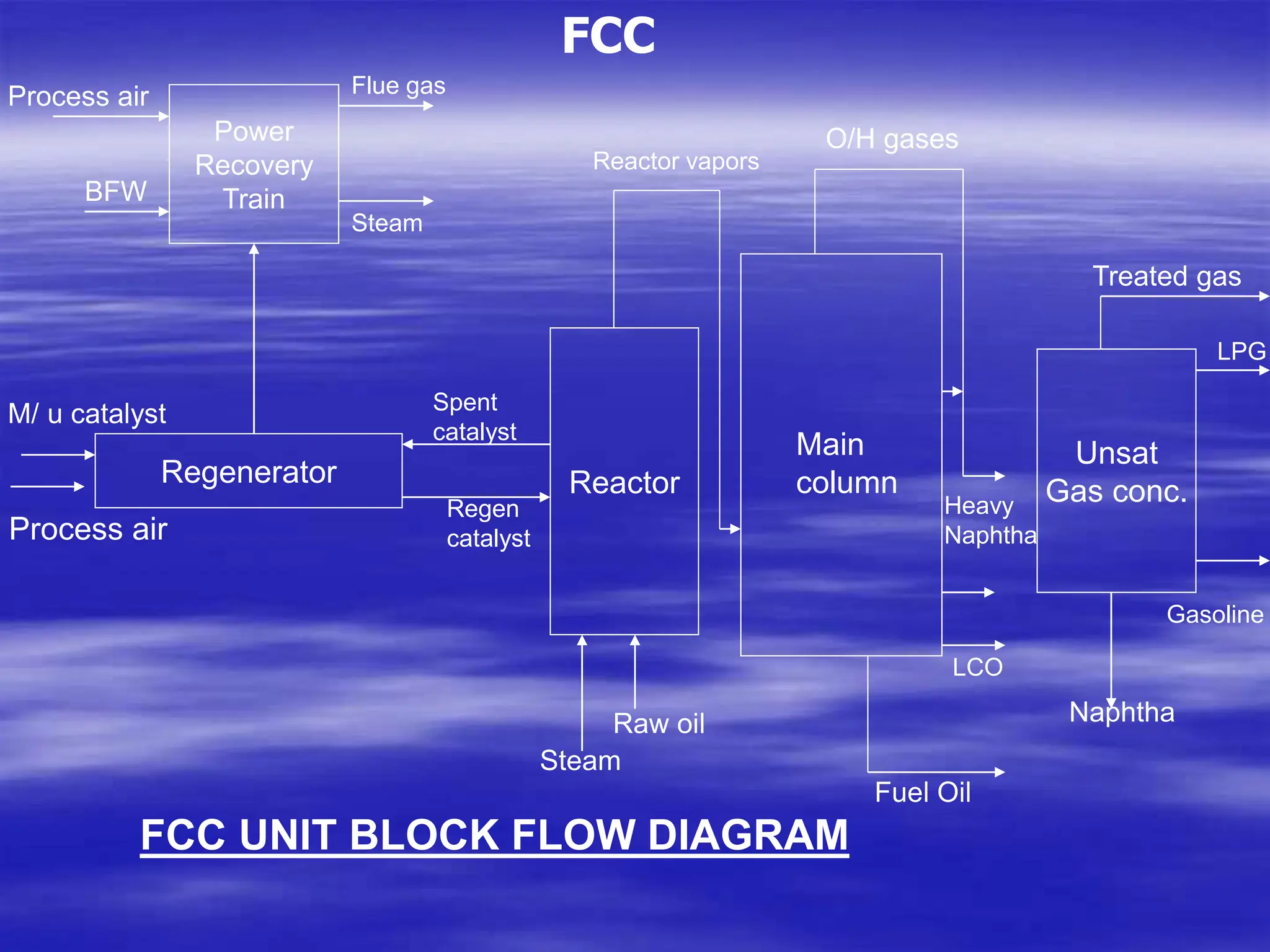
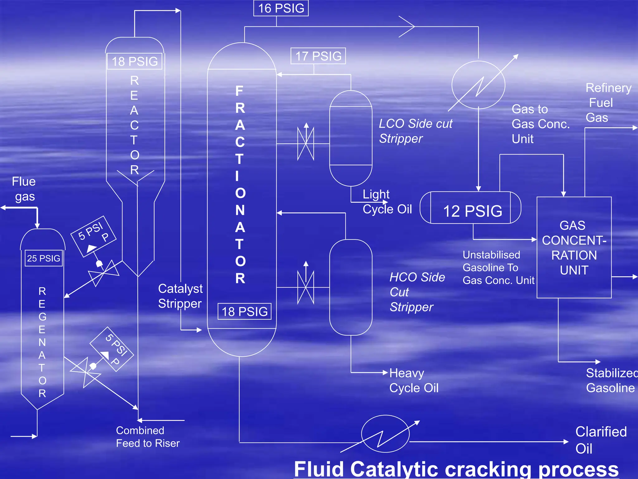
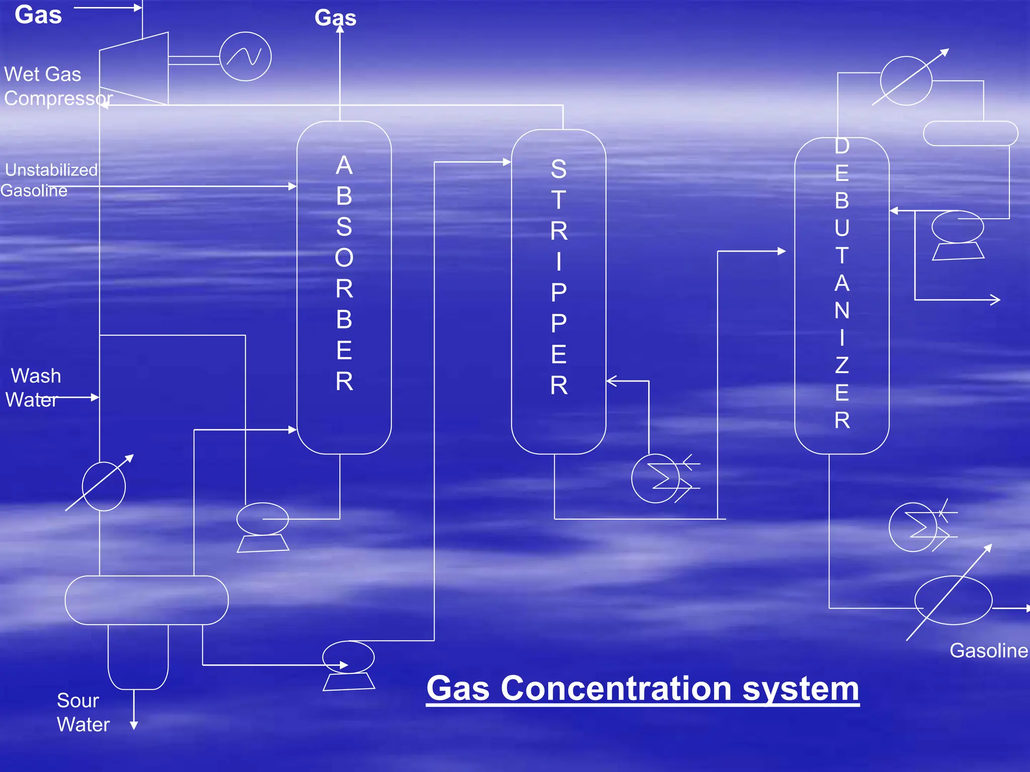
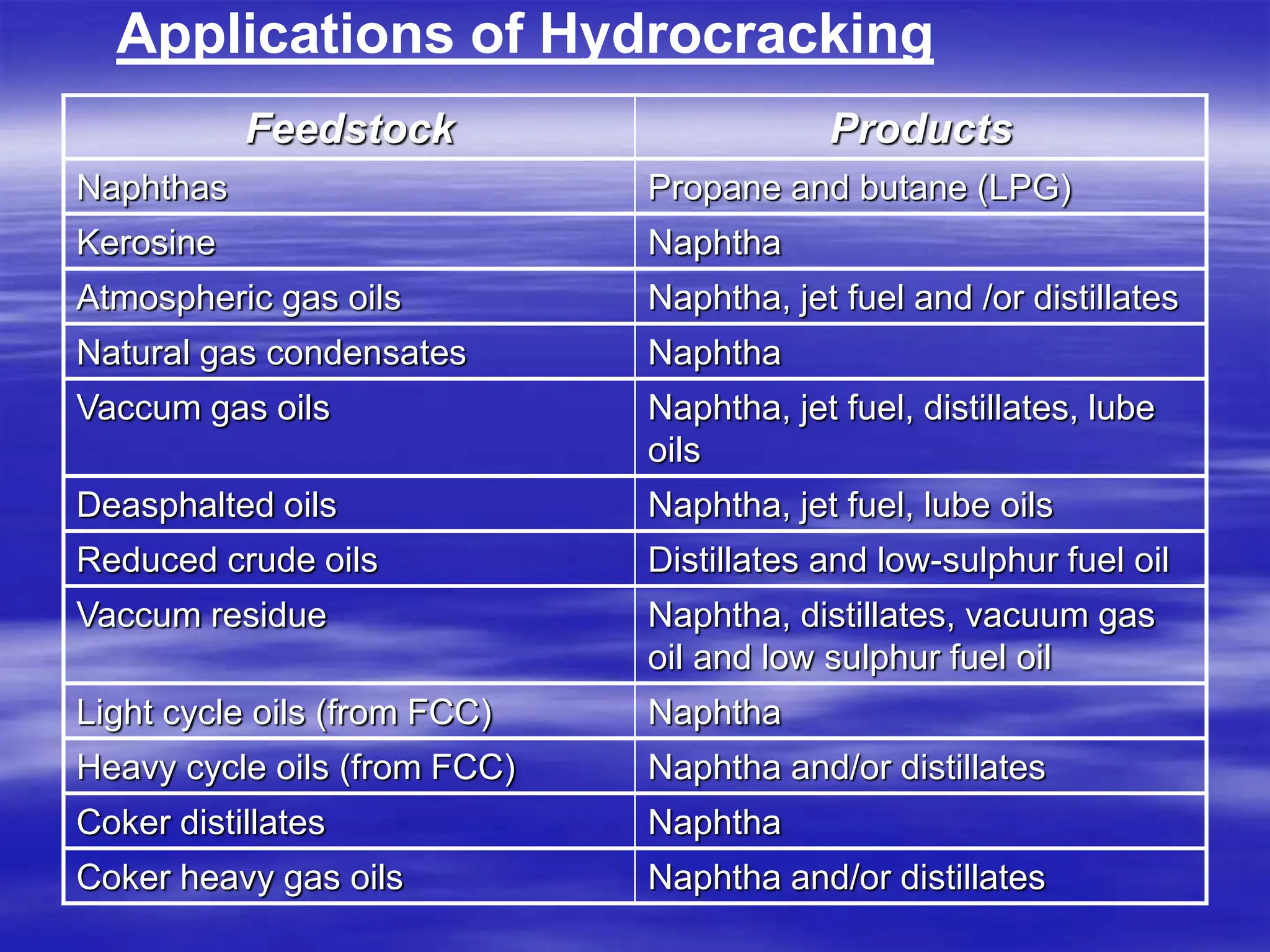
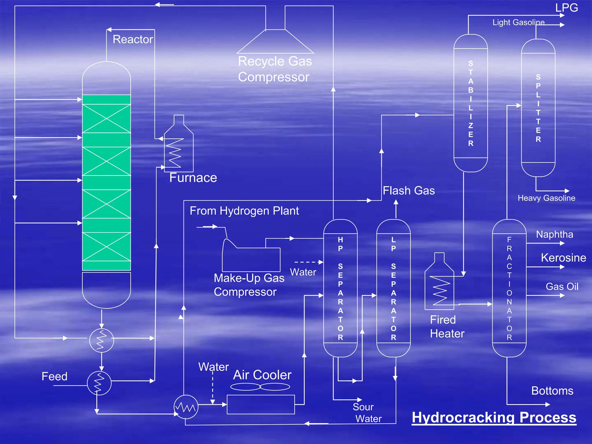
SlideShare a Scribd company logo
1 of 27
Module 7
CATALYTIC CONVERSION PROCESSES
 Fluid catalytic cracking
 Hydrocracking Heavy Oil cracking
 Isomerisation
 Catalytic Polymerization
 CATALYTIC CONVERSION PROCESSES
 Catalytic processes make it possible to remove unwanted
impurities such as sulfur compounds and to convert certain
hydrocarbons into the products which cannot be obtained by
simple distillation or through thermal conversion processes.
 Catalytic conversion processes may be broadly classified as
those:
i. Which change the carbon number
ii. Change the carbon / hydrogen ratio or
iii. Do not change the carbon number or C/H ratio
 Fluid catalytic cracking, hydrocracking and polymerization
processes change the carbon number.
C/H ratio is changed by hydrogenation and dehydrogenation.
Isomerization is the process that does not alter the carbon
number or C/H ratio.
 Fluid Catalytic Cracking:
FCC is a catalytic conversion process for converting heavy gas
oils such as vacuum distillates into more valuable products
such as LPG, Gasoline, Olefins, cycle oils etc. FCC is a low
pressure, intermediate to high temp. process. This process may
be designed and operated to achieve either of the following
objectives:
• Maximization of middle distillates
• Maximization of LPG and Gasoline.
 FCC process can accept a variety of feedstocks. FCC process
is a relatively low investment; reliable long run operations, and
an operating versatility that enables the refiner to produce a
variety of yield patterns by simple adjustment of operating
parameters.
 Process Description:
Hot regenerated catalyst is mixed at the bottom of reactor with
raw feed and steam. After pre-acceleration , it is brought in to
contact with the staged feeds supplied as finely atomized
droplets. Feed instantaneously vaporizes and travels up the
riser with the catalyst where conversion reaction takes place, At
the top of reactor, the vapour is disengaged from catalyst. The
vapour is sent to main fractionating column. In this column,
mainly LPG, Gasoline, middle distillates and decanted oil are
obtained. The spent catalyst is steam stripped to remove
hydrocarbon vapour and then sent to two stage regenerators
for burning coke before it is recycled to rector alongwith
makeup catalyst to reactor.
Air is injected in catalysts regenerator for burning coke. Water
generated in the system leaves with flue gas from Power
Recovery Train. Flue gases are sent to CO boiler and thereafter
to a clean up system to remove particulates, SOx and NOx.
ZSM additives is added to catalysts to increase LPG yield.
Residues are also used as feedstock in RFCC
Power
Recovery
Train
Regenerator Reactor
Unsat
Gas conc.
FCC
Process air
BFW
Main
column
Gasoline
LPG
O/H gases
Reactor vapors
Steam
Flue gas
Spent
catalyst
Regen
catalyst
Raw oil
Steam
Fuel Oil
LCO
Heavy
Naphtha
Treated gas
M/ u catalyst
Process air
FCC UNIT BLOCK FLOW DIAGRAM
Naphtha
Fluid Catalytic cracking process
GAS
CONCENT-
RATION
UNIT
18 PSIG
Flue
gas
16 PSIG
17 PSIG
Catalyst
Stripper
LCO Side cut
Stripper
Light
Cycle Oil
HCO Side
Cut
Stripper
Heavy
Cycle Oil
Clarified
Oil
Gas to
Gas Conc.
Unit
Refinery
Fuel
Gas
12 PSIG
Stabilized
Gasoline
Unstabilised
Gasoline To
Gas Conc. Unit
F
R
A
C
T
I
O
N
A
T
O
R
18 PSIG
R
E
A
C
T
O
R
R
E
G
E
N
A
T
O
R
25 PSIG
Combined
Feed to Riser
Principles of Operation:
 FCC process converts heavy gas oils into light hydrocarbon
gases, high octane gasoline and lower boiling gas oil
components. This is accomplished by cracking the vaporized
feed over the catalysts at a temp. between 4700C-5400C and a
pressure between 0.5 -1.5 Kg /cm2g. The catalysts lead to better
product selectivity as compared with that of thermal cracking
process.
 Catalyst:
•The catalyst used in the catalytic cracking process is a fine
powder made up of alumina and silica.
• The cracking reactions are accompanied by a heavy coke lay
down on the catalyst. The catalyst has to be frequently
regenerated by burning off the coke deposits. The problems
associated with frequent regeneration of catalyst have been
solved in the FCC units by circulating the catalyst in the fluidized
state from the reactor to the regenerator.
FCC complex has following sections :
(i) Reactor and Regenerator: In the reactor, the feedstock is
cracked to an effluent containing hydrocarbons ranging
from methane through the highest boiling material in the
feedstock plus hydrogen and H2S. In the regenerator; the
circulating spent catalysts is rejuvenated by burning the
deposited coke with air at high temperatures.
(ii) Main Fractionation column: In this column, the reactor
effluents are separated into various products, heavier
naphtha and cycle oils are separated as side cuts and
slurry oil is separated as a bottom product.
(iii) Gas concentration unit: In this section, usually referred
to as the ‘unsaturated Gas Plant’; the unstable gasoline
and the lighter products from the main-fractionators
overhead are separated into fuel gas, C1-C4’s for alkylation
or polymerization and debutanized gasoline.
A
B
S
O
R
B
E
R
S
T
R
I
P
P
E
R
D
E
B
U
T
A
N
I
Z
E
R
Gas
Wet Gas
Compressor
Gas
Unstabilized
Gasoline
Wash
Water
Sour
Water
Gasoline
Gas Concentration system
Energy Recovery in FCC unit:
In a FCC plant, the flue gases from the regenerator
contains significant amount of available energy that can be
recovered. The flue gas exits the regenerator at about
7000C- 7800C and at about 2 Kg/Cm2 g press. The thermal
and kinetic energy of the flue gas can be converted to steam
or used to drive a turboexpander-generator system for
power generation. Unconverted CO in the flue gas can be
combusted to CO2 in a CO boiler with production of high
pressure steam.
 HYDROCRACKING
Hydrocracking is cracking in presence of hydrogen.
Hydrocracking is vary versatile petroleum refining process.
Any fraction from naphtha to asphalt can be processed.
Depending upon the feedstock used, two types of
Hydrocracking is practised Industrially.
If the feedstock is a heavy distillate obtained from straight run
refining or cracking operation; it is called distillate
hydrocracking.
Residual Hydrocracking is the name given to the process if
the feedstcok happens to be residue of the straight run
refining. Residues are usually lower in API, higher in carbon
residues and C:H:Ratio as compared to the distillates. In
Residuum Hydrocracking a different type of catalyst is used at
relatively higher temps. Because the feedstocks in RH have
more metals and asphaltenes.
 The selective hydrocracking of vacuum gas oils and
propane deasphalted oil to produce high quality
Lubricating Oil Base Stocks (LOBS) is an important
application of Hydrocracking. Hydrocracking processes
Hydrocrack compounds of low viscosity Index into high
quality naphtha and distillates. By hydrocracking of
vacuum gas oils, the yield of Lubricating Oil can be
considerably increased compared to conventional
extraction processes.
Applications of Hydrocracking
Feedstock Products
Naphthas Propane and butane (LPG)
Kerosine Naphtha
Atmospheric gas oils Naphtha, jet fuel and /or distillates
Natural gas condensates Naphtha
Vaccum gas oils Naphtha, jet fuel, distillates, lube
oils
Deasphalted oils Naphtha, jet fuel, lube oils
Reduced crude oils Distillates and low-sulphur fuel oil
Vaccum residue Naphtha, distillates, vacuum gas
oil and low sulphur fuel oil
Light cycle oils (from FCC) Naphtha
Heavy cycle oils (from FCC) Naphtha and/or distillates
Coker distillates Naphtha
Coker heavy gas oils Naphtha and/or distillates
 A hydrocracking unit is costlier compared to catalytic
cracking unit (about 1.6 times). Products from
Hydrocracking are very stable but the operating cost of the
Hydrocracking unit is higher than a catalytic cracker unit.
The metallurgy of the hydrocracking unit needs special care,
is costly and more maintenance-intensive.
 Process Description:
The reactions in hydrocracking are:
 Cracking
 Saturation of Aromatics by Hydrogenation
 Saturation of Olefinic material present in feedstock
 Reaction of desulfurization, denitrogenation and deoxygenation.
There are 2 steps of reactions in Hydrocracking
-- Cracking step
-- Treating step
The cracking function is provided by Silica Alumina catalyst or
Zeolite Catalyst. Zeolite catalyst permits operation at lower
temperatures. Tungsten oxide or Nickel oxide catalysts promote
hydrogenation reaction.
 The simplest Hydrocracker configuration - the single stage
process - in which the cracking and treating step are
combined in one reactor finds application in cases where only
moderate degree of conversion (<60%) is required.
In a multistage process, the cracking reaction mainly takes
place in an added reactor. There could be 2 stages or 3 stages
Hydrocracker.
In the first reactor, desulfurization and denitrogenation occurs
besides a limited amount of hydrocracking. The catalyst is
arranged in a number of fixed beds. Reaction temps. are
controlled by introducing part of the recycle gas as a quench
medium between beds. The liquid from the first reactor is
fractionated to remove the product made in the first reactor.
The bottoms for the fractionators, after heat exchange with
reactor effluent and mixing with heated recycle gas; is sent to
the 2nd reactor. Most of the hydrocracking occurs here.
LPG
F
R
A
C
T
I
O
N
A
T
O
R
H
P
S
E
P
A
R
A
T
O
R
L
P
S
E
P
A
R
A
T
O
R
S
T
A
B
I
L
I
Z
E
R
S
P
L
I
T
T
E
R
Recycle Gas
Compressor
Furnace
From Hydrogen Plant
Make-Up Gas
Compressor
Air Cooler
Flash Gas
Water
Fired
Heater
Sour
Water
Water
Light Gasoline
Heavy Gasoline
Naphtha
Kerosine
Gas Oil
Bottoms
Feed
Reactor
Hydrocracking Process
• Hydrocracking is an extremely versatile process that
can be utilized in many different ways. One of the
advantages of hydrocracking is its ability to
breakdown high-boiling aromatic stocks produced by
catalytic cracking or coking.
 Hydrocracking Process Operations:
Conditions:
Solid acid catalyst (silica Alumina with rare earths)
2600C-4500C(Solid –Liquid Contact)
68-140 Kg/ Cm2 (g) H2 press.
Feeds:
Refractory (aromatics) stream
Most S,N, metals and H2O removed
Coker oils, Cycle oils.
Products:
Lower Mol.wt. isoparaffins
Some C4 gases
Residual Tar (recycle)
Variations
Fixed Bed
Ebullating Bed
Heavy Oil Cracking
The H oil process is basically a catalytic hydrogenation
technique in which, during the reaction, considerable
hydrocracking takes place. The process is used to upgrade
heavy sulfur containing crudes and residual stocks to high
quality sweet distillates, thus reducing fuel oil yield.
H. Oil ebullated bed reactor consists of a back-mixed
isothermal vessel with hydrogen and liquid feed flowing
upward expanding the catalyst evenly across the reactor
cross section while maintaining the suspended catalyst
particles in a well mixed state. Catalyst is added and with
drawn from the reaction chamber without shutdown, to
maintain uniform catalyst activity. After high pressure
recovery of liquid from recycled gas, products are separated
in a conventional distillation column.
The operating pressure for an H-oil unit is a function of feed
boiling point with operating pressure upto 200 bars used
when charging vacuum tower residuum.
H-oil process adopts an ebullated-bed reactor system
which has the advantage that small solid particles are
flushed out of the reactor and do not contribute to plugging
or increase in pressure drop through the reactor.
HYDROCRACKER
H2S
Removal
Heavy Fuel
Fractionators
Diesel
Ist Pool
Heavy Naphtha
Light Naphtha
Light Ends
L.P.seperator
Make Up
H2
Gas Oil
Heater
Recycle H2
Recycle H2
Stabilizer
Heater
Ist STG
Reactor
2nd STG
Reactor
COKE PRECURSOR
REMOVAL
L.P.
SEPERATOR
Make-up Hydrogen
Recycle Hydrogen
Products
stripper
steam
Heaters
Feed
Reactor
Separator
PSA
Unit
H.P .Separator
Ebullated Bed Resid Hydrocracking Unit
 CATALYTIC ISOMERIZATION:
Cataltic Isomerization process is used to convert n-butane to
isobutane which can be alkylated to give Liquid hydrocarbon in
the boiling range of motor gasoline. This process is also used to
convert low octane-number paraffins (C5/C6) contained in light
straight-run naphtha and raffinates from solvent extrn. units into
the higher octane-number products such as Isoparaffins.
Reactions: CH3
H3C—CH2– CH2– CH3 CH3 CH
CH3
Examples:
UOP’s Butamer Isomerizaion Process
UOP Penex Process
 The Isomerization process has become of utmost
importance in preparing the isobutane needed for making
alkylate as a basis for aviation gasoline
 CATALYTIC ALKYLATION:
Catalytic Alkylation process is used in Petroleum Refineries to
upgrade light olefins-mainly from FCC units, cokers and
visbreaker—and isobutane into highly branched paraffins. This
product is called alkylate which is used as a blending
component for making gasolines.
Reaction:
Alkylation reaction involves the reaction of isobutanes with a
light olefins such as propene or butenes, in the presence of an
acid catalyst-either concentrated sulfuric acid or anhydrous
Hydrofluoric Acid-to produce alkylate which is a mixture of
saturated, stable isoparaffins distilling in the gasoline range.
Processes:
HF Alkylation –UOP. Phillips Petroleum : H2SO4 based
Alkaylation-Exxon.
 CATALYTIC POLYMERIZATION
Catalytic polymerization in a petroleum refinery is used to
convert light olefins, such as propene and butenes; into a high
octane number motor gasoline components (polymer
gasoline). Catalytic polymerization is also used for producing
straight chain C7-C9 olefins which go into manufactures of
specialty alcohols.
The process can also be used for the alkylation of aromatics
with olefins to produce cumene or Ethyl Benzene.
Feedstock to the catalytic polymerization unit consist of C3-C4
products from fluid catalytic cracking as well as visbreaking
and coking operations.
UOP
IFP

More Related Content

Similar to 3 Catalytic Conversion Fluid catalytic conversion 27.ppt

VULCAN VGP-1000 High Temperature Mn Sulfur Guard Technology
VULCAN VGP-1000 High Temperature Mn Sulfur Guard TechnologyVULCAN VGP-1000 High Temperature Mn Sulfur Guard Technology
VULCAN VGP-1000 High Temperature Mn Sulfur Guard TechnologyGerard B. Hawkins
 
Petroleum Refinery Engineering-Part-2-30-July-2016
Petroleum Refinery Engineering-Part-2-30-July-2016Petroleum Refinery Engineering-Part-2-30-July-2016
Petroleum Refinery Engineering-Part-2-30-July-2016Muhammad Rashid Usman
 
Refining Process
Refining ProcessRefining Process
Refining ProcessMubarik Rao
 
IEC final presentation ceremony xfb nahi gg
IEC final presentation ceremony xfb nahi ggIEC final presentation ceremony xfb nahi gg
IEC final presentation ceremony xfb nahi ggHarrypotter333055
 
Hydrogen production in refinery
Hydrogen production in refineryHydrogen production in refinery
Hydrogen production in refineryAnupam Basu
 
Catalytic reforming.pptx
Catalytic reforming.pptxCatalytic reforming.pptx
Catalytic reforming.pptxSharuSharu15
 
Fundamentals of petroleum processing_ lecture7-1.pdf
Fundamentals of petroleum processing_ lecture7-1.pdfFundamentals of petroleum processing_ lecture7-1.pdf
Fundamentals of petroleum processing_ lecture7-1.pdfRobinsonA9
 
dimpfolderssecondsemforrefiningmodulesslides11hydrogenproduction-091009115333...
dimpfolderssecondsemforrefiningmodulesslides11hydrogenproduction-091009115333...dimpfolderssecondsemforrefiningmodulesslides11hydrogenproduction-091009115333...
dimpfolderssecondsemforrefiningmodulesslides11hydrogenproduction-091009115333...AJAYKUMAR801605
 
02 petrochemical processes
02 petrochemical processes02 petrochemical processes
02 petrochemical processesNaveen Choudhary
 
Refining Process.pdf
Refining Process.pdfRefining Process.pdf
Refining Process.pdfSana Khan
 
Chapter 5c -hydrocracking_i
Chapter 5c -hydrocracking_iChapter 5c -hydrocracking_i
Chapter 5c -hydrocracking_iHelena Francis
 
Catalytic Reforming .pdf
Catalytic Reforming .pdfCatalytic Reforming .pdf
Catalytic Reforming .pdfFaruk Eyigün
 

Similar to 3 Catalytic Conversion Fluid catalytic conversion 27.ppt (20)

FCC-Ch-21
FCC-Ch-21FCC-Ch-21
FCC-Ch-21
 
VULCAN VGP-1000 High Temperature Mn Sulfur Guard Technology
VULCAN VGP-1000 High Temperature Mn Sulfur Guard TechnologyVULCAN VGP-1000 High Temperature Mn Sulfur Guard Technology
VULCAN VGP-1000 High Temperature Mn Sulfur Guard Technology
 
Cracking
CrackingCracking
Cracking
 
Refinery basics
Refinery basicsRefinery basics
Refinery basics
 
Petroleum Refinery Engineering-Part-2-30-July-2016
Petroleum Refinery Engineering-Part-2-30-July-2016Petroleum Refinery Engineering-Part-2-30-July-2016
Petroleum Refinery Engineering-Part-2-30-July-2016
 
Refining Process
Refining ProcessRefining Process
Refining Process
 
IEC final presentation ceremony xfb nahi gg
IEC final presentation ceremony xfb nahi ggIEC final presentation ceremony xfb nahi gg
IEC final presentation ceremony xfb nahi gg
 
Hydrogen production in refinery
Hydrogen production in refineryHydrogen production in refinery
Hydrogen production in refinery
 
Chapter 5a -_cracking
Chapter 5a -_crackingChapter 5a -_cracking
Chapter 5a -_cracking
 
Catalytic reforming.pptx
Catalytic reforming.pptxCatalytic reforming.pptx
Catalytic reforming.pptx
 
Petroleum 8
Petroleum 8Petroleum 8
Petroleum 8
 
FCC
FCCFCC
FCC
 
Fundamentals of petroleum processing_ lecture7-1.pdf
Fundamentals of petroleum processing_ lecture7-1.pdfFundamentals of petroleum processing_ lecture7-1.pdf
Fundamentals of petroleum processing_ lecture7-1.pdf
 
dimpfolderssecondsemforrefiningmodulesslides11hydrogenproduction-091009115333...
dimpfolderssecondsemforrefiningmodulesslides11hydrogenproduction-091009115333...dimpfolderssecondsemforrefiningmodulesslides11hydrogenproduction-091009115333...
dimpfolderssecondsemforrefiningmodulesslides11hydrogenproduction-091009115333...
 
02 petrochemical processes
02 petrochemical processes02 petrochemical processes
02 petrochemical processes
 
Refining Process.pdf
Refining Process.pdfRefining Process.pdf
Refining Process.pdf
 
Chapter 5c -hydrocracking_i
Chapter 5c -hydrocracking_iChapter 5c -hydrocracking_i
Chapter 5c -hydrocracking_i
 
Heavy_residue_upgrading
Heavy_residue_upgradingHeavy_residue_upgrading
Heavy_residue_upgrading
 
Catalytic Reforming .pdf
Catalytic Reforming .pdfCatalytic Reforming .pdf
Catalytic Reforming .pdf
 
Pyrolysis of-biomass
Pyrolysis of-biomassPyrolysis of-biomass
Pyrolysis of-biomass
 

Recently uploaded

Operating System chapter 9 (Virtual Memory)
Operating System chapter 9 (Virtual Memory)Operating System chapter 9 (Virtual Memory)
Operating System chapter 9 (Virtual Memory)NareenAsad
 
8th International Conference on Soft Computing, Mathematics and Control (SMC ...
8th International Conference on Soft Computing, Mathematics and Control (SMC ...8th International Conference on Soft Computing, Mathematics and Control (SMC ...
8th International Conference on Soft Computing, Mathematics and Control (SMC ...josephjonse
 
AI in Healthcare Innovative use cases and applications.pdf
AI in Healthcare Innovative use cases and applications.pdfAI in Healthcare Innovative use cases and applications.pdf
AI in Healthcare Innovative use cases and applications.pdfmahaffeycheryld
 
Software Engineering Practical File Front Pages.pdf
Software Engineering Practical File Front Pages.pdfSoftware Engineering Practical File Front Pages.pdf
Software Engineering Practical File Front Pages.pdfssuser5c9d4b1
 
Diploma Engineering Drawing Qp-2024 Ece .pdf
Diploma Engineering Drawing Qp-2024 Ece .pdfDiploma Engineering Drawing Qp-2024 Ece .pdf
Diploma Engineering Drawing Qp-2024 Ece .pdfJNTUA
 
litvinenko_Henry_Intrusion_Hong-Kong_2024.pdf
litvinenko_Henry_Intrusion_Hong-Kong_2024.pdflitvinenko_Henry_Intrusion_Hong-Kong_2024.pdf
litvinenko_Henry_Intrusion_Hong-Kong_2024.pdfAlexander Litvinenko
 
handbook on reinforce concrete and detailing
handbook on reinforce concrete and detailinghandbook on reinforce concrete and detailing
handbook on reinforce concrete and detailingAshishSingh1301
 
Maher Othman Interior Design Portfolio..
Maher Othman Interior Design Portfolio..Maher Othman Interior Design Portfolio..
Maher Othman Interior Design Portfolio..MaherOthman7
 
Basics of Relay for Engineering Students
Basics of Relay for Engineering StudentsBasics of Relay for Engineering Students
Basics of Relay for Engineering Studentskannan348865
 
analog-vs-digital-communication (concept of analog and digital).pptx
analog-vs-digital-communication (concept of analog and digital).pptxanalog-vs-digital-communication (concept of analog and digital).pptx
analog-vs-digital-communication (concept of analog and digital).pptxKarpagam Institute of Teechnology
 
What is Coordinate Measuring Machine? CMM Types, Features, Functions
What is Coordinate Measuring Machine? CMM Types, Features, FunctionsWhat is Coordinate Measuring Machine? CMM Types, Features, Functions
What is Coordinate Measuring Machine? CMM Types, Features, FunctionsVIEW
 
Dynamo Scripts for Task IDs and Space Naming.pptx
Dynamo Scripts for Task IDs and Space Naming.pptxDynamo Scripts for Task IDs and Space Naming.pptx
Dynamo Scripts for Task IDs and Space Naming.pptxMustafa Ahmed
 
ALCOHOL PRODUCTION- Beer Brewing Process.pdf
ALCOHOL PRODUCTION- Beer Brewing Process.pdfALCOHOL PRODUCTION- Beer Brewing Process.pdf
ALCOHOL PRODUCTION- Beer Brewing Process.pdfMadan Karki
 
electrical installation and maintenance.
electrical installation and maintenance.electrical installation and maintenance.
electrical installation and maintenance.benjamincojr
 
Seismic Hazard Assessment Software in Python by Prof. Dr. Costas Sachpazis
Seismic Hazard Assessment Software in Python by Prof. Dr. Costas SachpazisSeismic Hazard Assessment Software in Python by Prof. Dr. Costas Sachpazis
Seismic Hazard Assessment Software in Python by Prof. Dr. Costas SachpazisDr.Costas Sachpazis
 
Worksharing and 3D Modeling with Revit.pptx
Worksharing and 3D Modeling with Revit.pptxWorksharing and 3D Modeling with Revit.pptx
Worksharing and 3D Modeling with Revit.pptxMustafa Ahmed
 
SLIDESHARE PPT-DECISION MAKING METHODS.pptx
SLIDESHARE PPT-DECISION MAKING METHODS.pptxSLIDESHARE PPT-DECISION MAKING METHODS.pptx
SLIDESHARE PPT-DECISION MAKING METHODS.pptxCHAIRMAN M
 
Research Methodolgy & Intellectual Property Rights Series 2
Research Methodolgy & Intellectual Property Rights Series 2Research Methodolgy & Intellectual Property Rights Series 2
Research Methodolgy & Intellectual Property Rights Series 2T.D. Shashikala
 
Geometric constructions Engineering Drawing.pdf
Geometric constructions Engineering Drawing.pdfGeometric constructions Engineering Drawing.pdf
Geometric constructions Engineering Drawing.pdfJNTUA
 
Final DBMS Manual (2).pdf final lab manual
Final DBMS Manual (2).pdf final lab manualFinal DBMS Manual (2).pdf final lab manual
Final DBMS Manual (2).pdf final lab manualBalamuruganV28
 

Recently uploaded (20)

Operating System chapter 9 (Virtual Memory)
Operating System chapter 9 (Virtual Memory)Operating System chapter 9 (Virtual Memory)
Operating System chapter 9 (Virtual Memory)
 
8th International Conference on Soft Computing, Mathematics and Control (SMC ...
8th International Conference on Soft Computing, Mathematics and Control (SMC ...8th International Conference on Soft Computing, Mathematics and Control (SMC ...
8th International Conference on Soft Computing, Mathematics and Control (SMC ...
 
AI in Healthcare Innovative use cases and applications.pdf
AI in Healthcare Innovative use cases and applications.pdfAI in Healthcare Innovative use cases and applications.pdf
AI in Healthcare Innovative use cases and applications.pdf
 
Software Engineering Practical File Front Pages.pdf
Software Engineering Practical File Front Pages.pdfSoftware Engineering Practical File Front Pages.pdf
Software Engineering Practical File Front Pages.pdf
 
Diploma Engineering Drawing Qp-2024 Ece .pdf
Diploma Engineering Drawing Qp-2024 Ece .pdfDiploma Engineering Drawing Qp-2024 Ece .pdf
Diploma Engineering Drawing Qp-2024 Ece .pdf
 
litvinenko_Henry_Intrusion_Hong-Kong_2024.pdf
litvinenko_Henry_Intrusion_Hong-Kong_2024.pdflitvinenko_Henry_Intrusion_Hong-Kong_2024.pdf
litvinenko_Henry_Intrusion_Hong-Kong_2024.pdf
 
handbook on reinforce concrete and detailing
handbook on reinforce concrete and detailinghandbook on reinforce concrete and detailing
handbook on reinforce concrete and detailing
 
Maher Othman Interior Design Portfolio..
Maher Othman Interior Design Portfolio..Maher Othman Interior Design Portfolio..
Maher Othman Interior Design Portfolio..
 
Basics of Relay for Engineering Students
Basics of Relay for Engineering StudentsBasics of Relay for Engineering Students
Basics of Relay for Engineering Students
 
analog-vs-digital-communication (concept of analog and digital).pptx
analog-vs-digital-communication (concept of analog and digital).pptxanalog-vs-digital-communication (concept of analog and digital).pptx
analog-vs-digital-communication (concept of analog and digital).pptx
 
What is Coordinate Measuring Machine? CMM Types, Features, Functions
What is Coordinate Measuring Machine? CMM Types, Features, FunctionsWhat is Coordinate Measuring Machine? CMM Types, Features, Functions
What is Coordinate Measuring Machine? CMM Types, Features, Functions
 
Dynamo Scripts for Task IDs and Space Naming.pptx
Dynamo Scripts for Task IDs and Space Naming.pptxDynamo Scripts for Task IDs and Space Naming.pptx
Dynamo Scripts for Task IDs and Space Naming.pptx
 
ALCOHOL PRODUCTION- Beer Brewing Process.pdf
ALCOHOL PRODUCTION- Beer Brewing Process.pdfALCOHOL PRODUCTION- Beer Brewing Process.pdf
ALCOHOL PRODUCTION- Beer Brewing Process.pdf
 
electrical installation and maintenance.
electrical installation and maintenance.electrical installation and maintenance.
electrical installation and maintenance.
 
Seismic Hazard Assessment Software in Python by Prof. Dr. Costas Sachpazis
Seismic Hazard Assessment Software in Python by Prof. Dr. Costas SachpazisSeismic Hazard Assessment Software in Python by Prof. Dr. Costas Sachpazis
Seismic Hazard Assessment Software in Python by Prof. Dr. Costas Sachpazis
 
Worksharing and 3D Modeling with Revit.pptx
Worksharing and 3D Modeling with Revit.pptxWorksharing and 3D Modeling with Revit.pptx
Worksharing and 3D Modeling with Revit.pptx
 
SLIDESHARE PPT-DECISION MAKING METHODS.pptx
SLIDESHARE PPT-DECISION MAKING METHODS.pptxSLIDESHARE PPT-DECISION MAKING METHODS.pptx
SLIDESHARE PPT-DECISION MAKING METHODS.pptx
 
Research Methodolgy & Intellectual Property Rights Series 2
Research Methodolgy & Intellectual Property Rights Series 2Research Methodolgy & Intellectual Property Rights Series 2
Research Methodolgy & Intellectual Property Rights Series 2
 
Geometric constructions Engineering Drawing.pdf
Geometric constructions Engineering Drawing.pdfGeometric constructions Engineering Drawing.pdf
Geometric constructions Engineering Drawing.pdf
 
Final DBMS Manual (2).pdf final lab manual
Final DBMS Manual (2).pdf final lab manualFinal DBMS Manual (2).pdf final lab manual
Final DBMS Manual (2).pdf final lab manual
 

3 Catalytic Conversion Fluid catalytic conversion 27.ppt

  • 1. Module 7 CATALYTIC CONVERSION PROCESSES CATALYTIC CONVERSION PROCESSES  Fluid catalytic cracking  Hydrocracking Heavy Oil cracking  Isomerisation  Catalytic Polymerization
  • 2.  CATALYTIC CONVERSION PROCESSES  Catalytic processes make it possible to remove unwanted impurities such as sulfur compounds and to convert certain hydrocarbons into the products which cannot be obtained by simple distillation or through thermal conversion processes.  Catalytic conversion processes may be broadly classified as those: i. Which change the carbon number ii. Change the carbon / hydrogen ratio or iii. Do not change the carbon number or C/H ratio  Fluid catalytic cracking, hydrocracking and polymerization processes change the carbon number. C/H ratio is changed by hydrogenation and dehydrogenation. Isomerization is the process that does not alter the carbon number or C/H ratio.
  • 3.  Fluid Catalytic Cracking: FCC is a catalytic conversion process for converting heavy gas oils such as vacuum distillates into more valuable products such as LPG, Gasoline, Olefins, cycle oils etc. FCC is a low pressure, intermediate to high temp. process. This process may be designed and operated to achieve either of the following objectives: • Maximization of middle distillates • Maximization of LPG and Gasoline.  FCC process can accept a variety of feedstocks. FCC process is a relatively low investment; reliable long run operations, and an operating versatility that enables the refiner to produce a variety of yield patterns by simple adjustment of operating parameters.
  • 4.  Process Description: Hot regenerated catalyst is mixed at the bottom of reactor with raw feed and steam. After pre-acceleration , it is brought in to contact with the staged feeds supplied as finely atomized droplets. Feed instantaneously vaporizes and travels up the riser with the catalyst where conversion reaction takes place, At the top of reactor, the vapour is disengaged from catalyst. The vapour is sent to main fractionating column. In this column, mainly LPG, Gasoline, middle distillates and decanted oil are obtained. The spent catalyst is steam stripped to remove hydrocarbon vapour and then sent to two stage regenerators for burning coke before it is recycled to rector alongwith makeup catalyst to reactor. Air is injected in catalysts regenerator for burning coke. Water generated in the system leaves with flue gas from Power Recovery Train. Flue gases are sent to CO boiler and thereafter to a clean up system to remove particulates, SOx and NOx. ZSM additives is added to catalysts to increase LPG yield. Residues are also used as feedstock in RFCC
  • 5. Power Recovery Train Regenerator Reactor Unsat Gas conc. FCC Process air BFW Main column Gasoline LPG O/H gases Reactor vapors Steam Flue gas Spent catalyst Regen catalyst Raw oil Steam Fuel Oil LCO Heavy Naphtha Treated gas M/ u catalyst Process air FCC UNIT BLOCK FLOW DIAGRAM Naphtha
  • 6. Fluid Catalytic cracking process GAS CONCENT- RATION UNIT 18 PSIG Flue gas 16 PSIG 17 PSIG Catalyst Stripper LCO Side cut Stripper Light Cycle Oil HCO Side Cut Stripper Heavy Cycle Oil Clarified Oil Gas to Gas Conc. Unit Refinery Fuel Gas 12 PSIG Stabilized Gasoline Unstabilised Gasoline To Gas Conc. Unit F R A C T I O N A T O R 18 PSIG R E A C T O R R E G E N A T O R 25 PSIG Combined Feed to Riser
  • 7. Principles of Operation:  FCC process converts heavy gas oils into light hydrocarbon gases, high octane gasoline and lower boiling gas oil components. This is accomplished by cracking the vaporized feed over the catalysts at a temp. between 4700C-5400C and a pressure between 0.5 -1.5 Kg /cm2g. The catalysts lead to better product selectivity as compared with that of thermal cracking process.  Catalyst: •The catalyst used in the catalytic cracking process is a fine powder made up of alumina and silica. • The cracking reactions are accompanied by a heavy coke lay down on the catalyst. The catalyst has to be frequently regenerated by burning off the coke deposits. The problems associated with frequent regeneration of catalyst have been solved in the FCC units by circulating the catalyst in the fluidized state from the reactor to the regenerator.
  • 8. FCC complex has following sections : (i) Reactor and Regenerator: In the reactor, the feedstock is cracked to an effluent containing hydrocarbons ranging from methane through the highest boiling material in the feedstock plus hydrogen and H2S. In the regenerator; the circulating spent catalysts is rejuvenated by burning the deposited coke with air at high temperatures. (ii) Main Fractionation column: In this column, the reactor effluents are separated into various products, heavier naphtha and cycle oils are separated as side cuts and slurry oil is separated as a bottom product. (iii) Gas concentration unit: In this section, usually referred to as the ‘unsaturated Gas Plant’; the unstable gasoline and the lighter products from the main-fractionators overhead are separated into fuel gas, C1-C4’s for alkylation or polymerization and debutanized gasoline.
  • 10. Energy Recovery in FCC unit: In a FCC plant, the flue gases from the regenerator contains significant amount of available energy that can be recovered. The flue gas exits the regenerator at about 7000C- 7800C and at about 2 Kg/Cm2 g press. The thermal and kinetic energy of the flue gas can be converted to steam or used to drive a turboexpander-generator system for power generation. Unconverted CO in the flue gas can be combusted to CO2 in a CO boiler with production of high pressure steam.
  • 11.  HYDROCRACKING Hydrocracking is cracking in presence of hydrogen. Hydrocracking is vary versatile petroleum refining process. Any fraction from naphtha to asphalt can be processed. Depending upon the feedstock used, two types of Hydrocracking is practised Industrially. If the feedstock is a heavy distillate obtained from straight run refining or cracking operation; it is called distillate hydrocracking. Residual Hydrocracking is the name given to the process if the feedstcok happens to be residue of the straight run refining. Residues are usually lower in API, higher in carbon residues and C:H:Ratio as compared to the distillates. In Residuum Hydrocracking a different type of catalyst is used at relatively higher temps. Because the feedstocks in RH have more metals and asphaltenes.
  • 12.  The selective hydrocracking of vacuum gas oils and propane deasphalted oil to produce high quality Lubricating Oil Base Stocks (LOBS) is an important application of Hydrocracking. Hydrocracking processes Hydrocrack compounds of low viscosity Index into high quality naphtha and distillates. By hydrocracking of vacuum gas oils, the yield of Lubricating Oil can be considerably increased compared to conventional extraction processes.
  • 13. Applications of Hydrocracking Feedstock Products Naphthas Propane and butane (LPG) Kerosine Naphtha Atmospheric gas oils Naphtha, jet fuel and /or distillates Natural gas condensates Naphtha Vaccum gas oils Naphtha, jet fuel, distillates, lube oils Deasphalted oils Naphtha, jet fuel, lube oils Reduced crude oils Distillates and low-sulphur fuel oil Vaccum residue Naphtha, distillates, vacuum gas oil and low sulphur fuel oil Light cycle oils (from FCC) Naphtha Heavy cycle oils (from FCC) Naphtha and/or distillates Coker distillates Naphtha Coker heavy gas oils Naphtha and/or distillates
  • 14.  A hydrocracking unit is costlier compared to catalytic cracking unit (about 1.6 times). Products from Hydrocracking are very stable but the operating cost of the Hydrocracking unit is higher than a catalytic cracker unit. The metallurgy of the hydrocracking unit needs special care, is costly and more maintenance-intensive.
  • 15.  Process Description: The reactions in hydrocracking are:  Cracking  Saturation of Aromatics by Hydrogenation  Saturation of Olefinic material present in feedstock  Reaction of desulfurization, denitrogenation and deoxygenation. There are 2 steps of reactions in Hydrocracking -- Cracking step -- Treating step The cracking function is provided by Silica Alumina catalyst or Zeolite Catalyst. Zeolite catalyst permits operation at lower temperatures. Tungsten oxide or Nickel oxide catalysts promote hydrogenation reaction.  The simplest Hydrocracker configuration - the single stage process - in which the cracking and treating step are combined in one reactor finds application in cases where only moderate degree of conversion (<60%) is required.
  • 16. In a multistage process, the cracking reaction mainly takes place in an added reactor. There could be 2 stages or 3 stages Hydrocracker. In the first reactor, desulfurization and denitrogenation occurs besides a limited amount of hydrocracking. The catalyst is arranged in a number of fixed beds. Reaction temps. are controlled by introducing part of the recycle gas as a quench medium between beds. The liquid from the first reactor is fractionated to remove the product made in the first reactor. The bottoms for the fractionators, after heat exchange with reactor effluent and mixing with heated recycle gas; is sent to the 2nd reactor. Most of the hydrocracking occurs here.
  • 17. LPG F R A C T I O N A T O R H P S E P A R A T O R L P S E P A R A T O R S T A B I L I Z E R S P L I T T E R Recycle Gas Compressor Furnace From Hydrogen Plant Make-Up Gas Compressor Air Cooler Flash Gas Water Fired Heater Sour Water Water Light Gasoline Heavy Gasoline Naphtha Kerosine Gas Oil Bottoms Feed Reactor Hydrocracking Process
  • 18. • Hydrocracking is an extremely versatile process that can be utilized in many different ways. One of the advantages of hydrocracking is its ability to breakdown high-boiling aromatic stocks produced by catalytic cracking or coking.
  • 19.  Hydrocracking Process Operations: Conditions: Solid acid catalyst (silica Alumina with rare earths) 2600C-4500C(Solid –Liquid Contact) 68-140 Kg/ Cm2 (g) H2 press. Feeds: Refractory (aromatics) stream Most S,N, metals and H2O removed Coker oils, Cycle oils. Products: Lower Mol.wt. isoparaffins Some C4 gases Residual Tar (recycle) Variations Fixed Bed Ebullating Bed
  • 20. Heavy Oil Cracking The H oil process is basically a catalytic hydrogenation technique in which, during the reaction, considerable hydrocracking takes place. The process is used to upgrade heavy sulfur containing crudes and residual stocks to high quality sweet distillates, thus reducing fuel oil yield. H. Oil ebullated bed reactor consists of a back-mixed isothermal vessel with hydrogen and liquid feed flowing upward expanding the catalyst evenly across the reactor cross section while maintaining the suspended catalyst particles in a well mixed state. Catalyst is added and with drawn from the reaction chamber without shutdown, to maintain uniform catalyst activity. After high pressure recovery of liquid from recycled gas, products are separated in a conventional distillation column.
  • 21. The operating pressure for an H-oil unit is a function of feed boiling point with operating pressure upto 200 bars used when charging vacuum tower residuum. H-oil process adopts an ebullated-bed reactor system which has the advantage that small solid particles are flushed out of the reactor and do not contribute to plugging or increase in pressure drop through the reactor.
  • 22. HYDROCRACKER H2S Removal Heavy Fuel Fractionators Diesel Ist Pool Heavy Naphtha Light Naphtha Light Ends L.P.seperator Make Up H2 Gas Oil Heater Recycle H2 Recycle H2 Stabilizer Heater Ist STG Reactor 2nd STG Reactor
  • 23. COKE PRECURSOR REMOVAL L.P. SEPERATOR Make-up Hydrogen Recycle Hydrogen Products stripper steam Heaters Feed Reactor Separator PSA Unit H.P .Separator Ebullated Bed Resid Hydrocracking Unit
  • 24.  CATALYTIC ISOMERIZATION: Cataltic Isomerization process is used to convert n-butane to isobutane which can be alkylated to give Liquid hydrocarbon in the boiling range of motor gasoline. This process is also used to convert low octane-number paraffins (C5/C6) contained in light straight-run naphtha and raffinates from solvent extrn. units into the higher octane-number products such as Isoparaffins. Reactions: CH3 H3C—CH2– CH2– CH3 CH3 CH CH3 Examples: UOP’s Butamer Isomerizaion Process UOP Penex Process
  • 25.  The Isomerization process has become of utmost importance in preparing the isobutane needed for making alkylate as a basis for aviation gasoline
  • 26.  CATALYTIC ALKYLATION: Catalytic Alkylation process is used in Petroleum Refineries to upgrade light olefins-mainly from FCC units, cokers and visbreaker—and isobutane into highly branched paraffins. This product is called alkylate which is used as a blending component for making gasolines. Reaction: Alkylation reaction involves the reaction of isobutanes with a light olefins such as propene or butenes, in the presence of an acid catalyst-either concentrated sulfuric acid or anhydrous Hydrofluoric Acid-to produce alkylate which is a mixture of saturated, stable isoparaffins distilling in the gasoline range. Processes: HF Alkylation –UOP. Phillips Petroleum : H2SO4 based Alkaylation-Exxon.
  • 27.  CATALYTIC POLYMERIZATION Catalytic polymerization in a petroleum refinery is used to convert light olefins, such as propene and butenes; into a high octane number motor gasoline components (polymer gasoline). Catalytic polymerization is also used for producing straight chain C7-C9 olefins which go into manufactures of specialty alcohols. The process can also be used for the alkylation of aromatics with olefins to produce cumene or Ethyl Benzene. Feedstock to the catalytic polymerization unit consist of C3-C4 products from fluid catalytic cracking as well as visbreaking and coking operations. UOP IFP