Downloaded 1,883 times

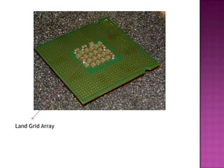


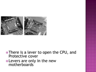

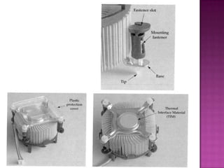
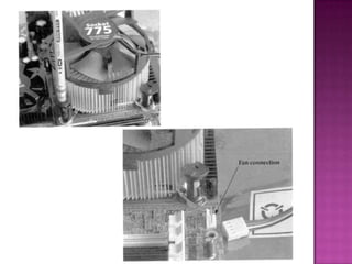

The document discusses the CPU (central processing unit), which is the brain of the computer that carries out instructions. It describes the parts of the CPU including the socket and cooling assembly. The summary provides step-by-step instructions for removing an old CPU, installing a new CPU, applying thermal compound, and securing the cooling assembly.