Downloaded 32 times


![5
Introduction:
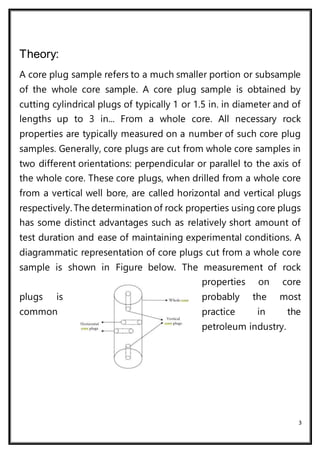
A plug, or sample, taken from a conventional core for analysis. Core
plugs are typically 1 in. to 1 1/2 in. [2.5 to 3.8 cm] in diameter and
1 in. to 2 in. [5 cm] long. Core plugs are ordinarily cut perpendicular
to the axis of the core or parallel to the axis, called horizontal and
vertical plugs, respectively, when cut from a vertical wellbore. The
terms horizontal and vertical are often applied for cores cut from a
deviated or horizontal wellbore, even though they are not strictly
correct unless core orientation is measured and plugs are cut to
the true in-situ orientation.](https://image.slidesharecdn.com/1coreplugtest-muhammadfaisal-170116005552/85/Core-plug-test-5-320.jpg)
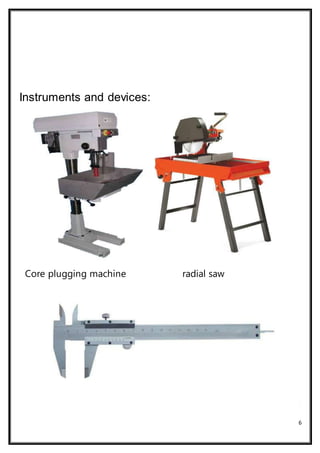


The aim of the experiment was to prepare a typical core plug from a rock sample. Core plugs are cylindrical samples cut from rock cores that are used to measure properties like porosity and permeability. The experiment involved cutting a core sample into plugs using a core plugging machine with a radial saw and coolant system. Measurements of the plug diameters were then taken with a ruler. Questions were discussed around issues with core plug data, the data obtained from plugs, and why the cutting machines have cooling systems.


