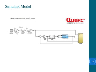
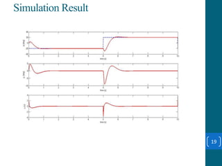
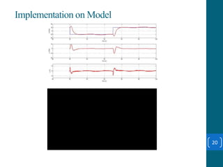
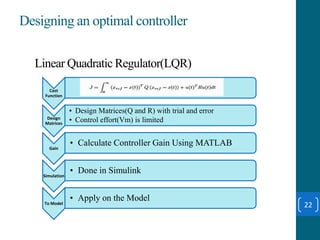
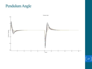
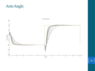
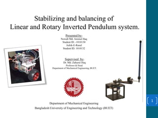
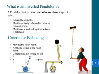
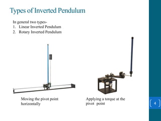
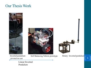
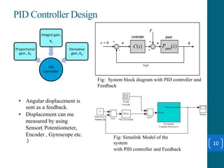
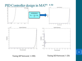
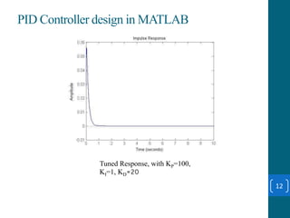
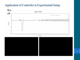
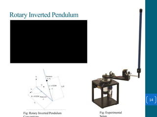
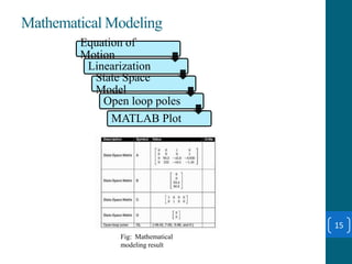
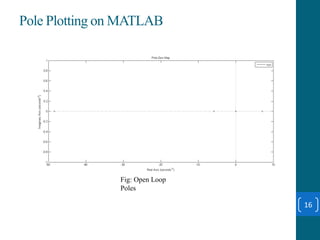
This document summarizes a student project on stabilizing and balancing linear and rotary inverted pendulum systems. It discusses the design and implementation of PID controllers to balance an inverted pendulum mounted on a cart (linear system) and a rotary inverted pendulum prototype. Key steps included mathematical modeling, simulation in MATLAB, PID controller tuning, and applying the controller to experimental setups. Results showed the systems could be stabilized using optimized PID and LQR controllers designed via pole placement and minimizing cost functions.


![Controller Design(Pole Placement Method)
17
Controll
ability
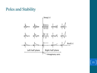
Desired
Poles
• ζ = 0.7.
• ωn = 4 rad/s
• |α| < 15 deg.
•
Gain
Calculat
ion
• To move the poles to desired location
Simulati
on
• Simulate The result
To
Model
• Apply on the system
2
. . . ]
( )
[ n
Ran
T B
k
AB A B A B
T n
3 430, 40p p ](https://image.slidesharecdn.com/thesispresentationoninvertedpendulum-160208210316/85/Thesis-presentation-on-inverted-pendulum-17-320.jpg)