Downloaded 147 times


![11
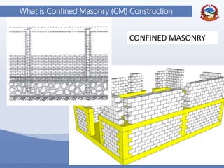
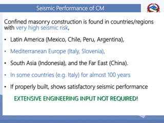
Confined Masonry in Nepal - Context
• Construction of reinforced concrete frame and masonry wall is trending in cities
and towns
• Heavy damage observed in those construction in the last earthquake even in low
PGA and spectral acceleration
• Non-ductile RC frame construction
• Unreinforced masonry walls vulnerable to lateral loading
• The presence of wall is in RC construction is not utilized as well as the
consequence of irregularity is overlooked
Confined masonry construction provides opportunity for improved performance in
earthquake utilizing constriction from both RC and masonry components
[technologies which require similar (preferably lower) level of construction skills and
are economically viable]
Its simple in design and analogues to conventional construction of RC frame with
walls (EXTENSIVE ENGINEERING INPUT NOT REQUIRED)](https://image.slidesharecdn.com/confinedmasonryoverview-170602140506/85/Confined-masonry-overview-11-320.jpg)
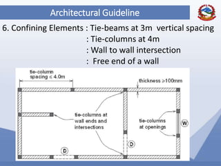
![79
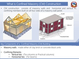
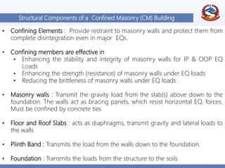
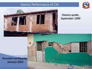
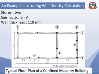
An Example Illustrating Wall Density Calculation
1. Floor area per floor = 4*9.2 = 36.8 m^2
Total floor area for 2 floors
TOTAL FLOOR AREA = 2*36.8 = 73.6 m^2
2. Wall density in the longitudinal direction
Wall area ( walls 1 & 2 only) :
Wall Area = [9.2+(9.2-1.2)]*(0.11) = 1.9 m^2
𝑾𝒂𝒍𝒍 𝑫𝒆𝒏𝒔𝒊𝒕𝒚 =
𝑾𝒂𝒍𝒍 𝑨𝒓𝒆𝒂
𝑻𝒐𝒕𝒂𝒍 𝑭𝒍𝒐𝒐𝒓 𝑨𝒓𝒆𝒂
=
𝟏. 𝟗
𝟕𝟑. 𝟔
= 𝟎. 𝟎𝟐𝟔 = 2.6 %](https://image.slidesharecdn.com/confinedmasonryoverview-170602140506/85/Confined-masonry-overview-74-320.jpg)
![80
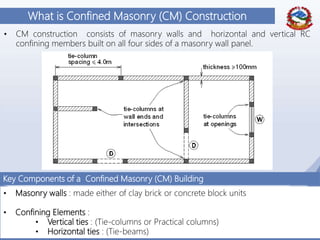
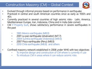
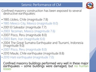
An Example Illustrating Wall Density Calculation
3. Wall density in the Transverse direction
Wall area ( walls A, B & C) :
Wall Area=[4.0+(4.0-1.2)+4.0-1.2]*(0.11) = 1.1 m^2
𝑾𝒂𝒍𝒍 𝑫𝒆𝒏𝒔𝒊𝒕𝒚 =
𝑾𝒂𝒍𝒍 𝑨𝒓𝒆𝒂
𝑻𝒐𝒕𝒂𝒍 𝑭𝒍𝒐𝒐𝒓 𝑨𝒓𝒆𝒂
=
𝟏. 𝟏
𝟕𝟑. 𝟔
= 𝟎. 𝟎𝟏𝟓 = 1.50 %](https://image.slidesharecdn.com/confinedmasonryoverview-170602140506/85/Confined-masonry-overview-75-320.jpg)


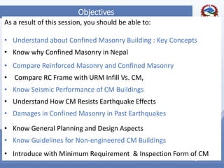
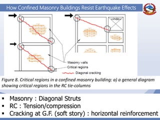
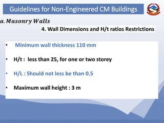
This document provides an overview of confined masonry construction. It defines confined masonry as consisting of masonry walls with horizontal and vertical reinforced concrete confining elements. The objectives are to understand key concepts of confined masonry, compare it to other construction types, understand its seismic performance based on past earthquakes, and learn general planning and design guidelines. Confined masonry has shown satisfactory seismic performance globally and is presented as an appropriate construction type for Nepal due to utilizing local materials and skills while improving earthquake resistance over other common methods.


