2. Click File>New. Although SAP2000 offers several templates, it’s often necessary to use grids in order to create a custom
structure. From the main menu, select units to be Kip, ft, F and click ‘Grid only’. Based on the G26_15 drawing, we see that the
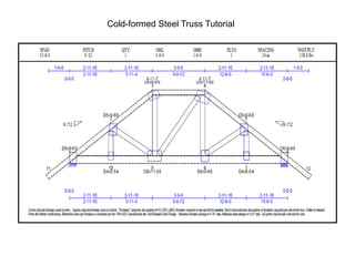
bottom chord is 15’8” long, and because the height of the truss was not provided, we must calculate the height of the truss
using other available dimensions. Take the bottom cord dimension of 5’11” 4/16 (5.9375’) and multiply by .75, which
corresponds to 9/12 pitch in order to determine truss height of 4.453’ (5.8375’ X .75). Since the truss will be modeled in XZ
plane (2D only), we’ll start by defining perimeter grids which we will refine later. Grid lines and spacing should be input as
shown below right, with 1 in the Y direction so as not to display it. Note in the Grid spacing X direction below, that SAP2000
enables you to input using architectural units, 15’8” in this example, and after you tab from that field it will automatically convert
to feet decimal. SAP2000 does not allow for additional fractional inch units such as 2’11” 10/16. Press OK to accept gridlines.
Type grid lines
and spacing
as shown
3. Click once in the left window to make it the ‘active’ window, then click the xz button which switches the planar view as
shown below right. Note the up/down arrows . If there were additional grids in the Y direction which there are not, for
future reference you can use these arrows to scroll through the model in any planar view. Units are located in the bottom
right portion of the main SAP2000 screen and can be changed anytime.
Click xz button XZ planar view
Units
4. Click ‘Draw special joint’ button , type 2.9687 in offset X, then click the bottom left corner (which happens to be the origin) to
draw the joint. If the ‘Draw special joint’ button does not appear on your palette, add it using the ‘more buttons’ icon or access
it under the Draw menu. We will generate our truss geometry by adding joints to supplement our grids, then we will connect
the dots to create our truss.
Click corner to
add joint using
specified offset
More
buttons
5. Keeping the offset the same, click the joint we just added to add another joint with the same offset. Next, change the
Offset X to 3.792 per the truss drawing and click the joint we just added to add a 3rd joint
Special joints can be offset from any
existing joint or grid intersection
Click here To add a new
joint here
6. Now type 2.9687 in Offset X and click the point we just added. Press Esc key on your keyboard or press Select button
to switch to select mode. While holding down your left mouse key, window around the two middle joints, then using the
main menu go to Edit>Replicate. Type 4.453 in the dz field (height of truss) and press OK.
Newly added joint
Two selected joints
7. Below left is what your model should look like now. Double click any gridline with your mouse or use Define
menu>Coordinate system/grids to display the Define grid system data dialogue shown below right. Add X gridlines for
-1 and 16.6667 and -.75 in the Z grid as shown to help us draw the sloped chord, then press OK to accept
8. With SAP2000, you can build your model and later come back to define and assign section properties, or draw and assign
section properties at the same time. The order doesn’t matter, so we’ll do it both ways in this tutorial. First, click Draw
frame/cable button as shown, use default FSEC1 section and continuous connection, and click once in the bottom left
corner of the grid and double click on the top joint as shown to draw one sloped chord. Snapping to grid intersections and
joints is typically how most models are created in SAP2000.
Click draw
frame button
9. Next, use the main menu to Define>Section properties>Frame sections. To define cold form steel sections, concrete sections, or
nonstandard steel sections, always click the ‘Add New property’ button. For standard steel shapes, you would click the ‘Import
New property’ button to select a steel library in order to import sections. In this example, we’re using cold form sections, so click
the ‘Add new property’ button. Change Frame Section property type to Cold Formed as shown below right and click the C
section to define.
10. Here we change the section name to whatever we want and type in the dimensions as shown. It may have been a little
more convenient to switch units (bottom right corner of SAP2000) to Kip-inches before defining sections, but as you can
see below, SAP will accept inch dimensions if you use the “ mark after the value as shown below in the Outside Width field.
We will accept the default cold form material. For future reference, please note that by clicking the “+” sign next to the
material, that would open a dialogue to define additional materials which could be used on any section. But for this
example we will accept the default material. Input dimensions as shown and press OK to accept in order to add it to the
working list.
11. Click ‘Add new property’ button to add another cold formed frame type. This time click to add a hat section, name it as
shown and type dimensions as shown, then press OK to add. Press OK on Frame properties dialogue to begin
modeling.
12. Click Draw frame/cable button again, but this time on the floating property dialogue click the Section with your mouse to
select C-1 as shown with continuous connection and click once in the bottom right corner as shown, then double click
the mouse at top to draw the other sloped chord.
13. Next, draw another C-1 frame section between the two joints as shown, but before drawing, click to change Moment
releases to Pinned as shown
14. Click to switch moment releases back to continuous and draw the bottom chord as shown below, drawing it as one long
member. Use the grid intersections to help you snap, since the snap to points and grid intersections button is activated
by default
Draw the bottom chord as one long member. Click once on the far left
and double click once on the far right as shown
15. Click the ‘snap to lines and edges’ snap tool as shown below, change the section to HAT-1 and moment releases to Pinned,
then draw frame starting at bottom joint. As soon as you begin to draw, type the letter V on your keyboard to lock the draw
frame onto vertical only as shown. As soon as you see the line tool tip as shown which indicates the intersection with the
sloped chord, click again to complete the vertical brace
Snap to
lines and
edges
16. Continue drawing as shown to connect the dots using the same HAT-1 section with pinned releases. After drawing the
vertical brace, right mouse click to draw at another location at the bottom as shown.
17. Draw as shown from the bottom chord upward typing V on the keyboard as before to lock on to the
sloping line where you click to draw the vertical brace. Then draw from that point down to the base of
the next vertical bracing as shown bottom right. Press Esc key on your keyboard or click Select button
to exit draw mode.
Draw final brace as shown
18. Click anywhere in the 3D view window to make it active, then click ‘set display options’ button and checkbox ‘Extrude
view’ as shown to render the model in 3D view. As we can see, the initial sloped chord that we drew needs to be re-
assigned a new section, and we may have to rotate local axes of frames. Extruded view is a useful tool for checking errors
in section assignments and local axes.
Set Display options are also useful to graphically view moment
releases of frames as well as view local axes and labels.
19. Click FSEC1 frame section to select it, then from main menu Assign>Frame>Section, highlight C-1 as shown and press
OK to assign a new section to it.
20. Click window zoom button and window around the horizontal top chord to zoom in to view local axis. Click the two
sloped chords and the horizontal chord as shown to select, then Assign>Frame>Local axes, type -90 degrees and
press OK to rotate as shown
All 3 top chord members selected
21. Click to select bottom chord and Assign>Frame>Local axes, but this time, rotate positive 90 degrees. Use this assignment to
rotate local axes of any frame members. For information purposes and future reference only, note that the Assign>Frame
menu can also be used to assign end releases and partial fixity as shown below right. For this tutorial, we handle releases by
choosing Pinned or Continuous from the floating properties dialogue whenever we draw members.
End releases in each direction can be modified at any time by
selecting members and Assign>Frame>Releases/partial fixity.
The partial fixity option applies only if you have data on the
stiffness of the end connection.
22. Next step is to add restraint supports. Select the lower left joint shown below and Assign>Joint>Restraints to add a fixed
restraint as per the drawing. Then select lower right side joint and assign a roller type support in the vertical direction as per the
drawing.
23. In some cases, designers may not want to consider a roller or pinned joint restraint to be 100% free in the non-supported
directions. In situations like that, the designer can select the joint(s) and add springs by using Assign>Joint>Springs if partial fixity
or joint flexibility is to be considered. Next, let’s assign loads to the truss. Select the top horizontal chord and Assign>Frame
loads>Distributed, which brings up a Distributed load dialogue with default load case. In this example, we will add an additional
load case. Click the “+” to the left of DEAD which displays the Define Load Patterns. Overwrite the Load pattern name to be
Distributed, type LIVE as shown, then press ‘Add new load pattern’ button.
Next step click this
button to add new load
pattern to the list
Users can assign joint springs to
supplement or replace restraint
assignments
Click + sign to add load pattern
24. After pressing ‘Add new load pattern’, click OK to close the dialogue. Next, change Load pattern name from DEAD to Distributed,
change units to lb, ft, F and type a uniform distributed load of 30 plf as shown below and the load will display graphically in current
units (.03 klf). The DEAD load pattern/case by default automatically includes the selfweight of the structural members based on
section and material. In this example, we are adding additional weight to the selfweight DEAD pattern
25. Next, we will assign joint loads by selecting the two joints at the top of the truss as shown below, then Assign>Joint loads,
where we change units to lb, ft, F and assign 100lbs. in the –Z (gravity) direction under DEAD load pattern as shown below.
Press OK. Now we’re ready to begin analysis and AISI design. Go to Analyze menu>Set analysis options and click XZ
options since we will be analyzing this truss in 2D. Press OK.
Set analysis options to run 2D as shown
26. Before we analyze, we need to define load combinations using Define>Load combinations. In this example, click the ‘Add
Default design combos’ button, then select ‘Cold Formed Frame design’, which automatically generates load combinations for
design. If you click a load combination, you can ‘Modify/show’ it to see details of the load combination. Alternatively, users can
define their own load combinations
27. Click Run analysis button , then click ‘Run now’ button shown below. This will run the analysis to determine
deflections and forces & moments based on the applied loads. You will be prompted to give the model a name, then the
program will analyze.
28. De-select extruded view and go to Options menu>Windows and switch to three windows. You can display different output and
design results simultaneously in each window. The way you do this is to click inside a window to make it active, then use the
buttons to select ‘show deformed shape’ or ‘show forces/stresses’ and select a load case or combo. Below you see joint
deflections on the left, major moment diagram on upper right, and restraint/support reactions (in lbs) in the bottom right. If you
right click the bottom chord in the Moment 3-3 diagram, you will see that SAP2000 treats that chord as a single physical
member reporting it as 1 moment diagram rather than breaking it into 5 pieces at each brace intersection. This physical
member functionality is also applied to design.
Deformed shapes Moment diagrams and joint reactions
29. The next step is to run the AISI cold formed steel design check. Either add a button to do this on the top right, or use Design
menu>Cold formed steel frame design>Start design/check of the structure. The design will automatically produce a color coded
output. In this example, it appears that the top chord failed by a small margin whereas most of the other truss members have very
low ratios, which indicate that a lighter sections for the other members may be more economical. The next step is to right click this
chord to view more details.
Cold formed design button added
30. SAP2000 will automatically check every frame for every load combination at stations along the length of each frame and
report the worst case load combination and location along the length of the frame. In this example, the worst case ratio
exceeded the design allowable by less than 1%. Click Summary button to review design results for this chord member.
31. Close the summary page and click the ‘Overwrites’ button for this frame member. SAP2000 makes a lot of intelligent
design assumptions if the user accepts the defaults. However, in some cases these defaults are not adequate. In this case,
the default was that the chord was not through fastened to the deck. If it was through fastened to the deck, you would want
to take credit for that. Change from No to Yes and press OK.
32. That design parameter change lowered the design ratio to an acceptable 81% of allowable. To assign other design
parameters, select frame members that you want to assign, and after you’ve selected them go Design>Cold formed steel
frame design>View/revise overwrites to override program defaults.
33. Display menu>Show tables will generate output reports which can be sorted and formatted, with options to automatically
export to Excel and MS Access with bi-directional links withTekla.
34. The main portion of this tutorial is completed, but there is 1 minor issue to be aware of. If you look closely at the G26_15
dimensions, it appears the dimensions to the two tallest vertical braces were not to the centerline of the braces, but dimensioned
to their outer edges. In our model, we connected members using centerlines. In many cases, this centerline modeling approach
is adequate, and consideration of cardinal work points may be considered ‘splitting hairs’. However it can affect reactions, and if
a user wants to consider these cardinal work point locations in SAP2000, it’s easy enough to do. Click anywhere in your XZ
planar view window then use ‘set display options’ to activate extruded view in your XZ planar view as shown. Click the padlock
button to unlock your model, change units to lb, in, F, then click to select the tall vertical brace on the left side as shown, then
Assign>Frame>Insertion point. Change Coord system to ‘Global’ and type 1.2 inches in X direction End-I and End-J using ½ the
dimension of the HAT-1 section and press OK. In orthogonal modeling of beams and columns, use of the Cardinal point would
be all that would be needed, but since the chord is sloped, we need to specify the offset in this manner. Use of the Cardinal point
feature ‘moves’ the frame, but retains connectivity while automatically adding internal rigid links from the centerline of the
previous location to it’s new location in order to accurately account for changes in reactions.
35. Now select the tall vertical brace on the right side and assign a frame insertion point, but this time -1.2” in the X
direction in both I and J ends of the frame. While the frame insertion point dialogue is open, you can press F1 for Help
to read more about this feature.
36. Next, right click the sloped chord on the left to display info, and from the location tab we see that this chord is 104.06”
long. We’re going quickly cover an alternative modeling method for drawing sloped frames which may be useful in
certain situations. Press Ok to close the line information form, then left click to select the left side sloped chord and
press Del key on your keyboard to delete it.
37. We know that the chord is 104.0606” long with a pitch of 9/12. A pitch of 9/12 = angle 36.87 degrees. Click draw frame/cable
button, change Section to C-1 and Moment release Continuous and click the top of the left side vertical brace, then type S on
your keyboard and enter Fixed length of -104.0606 (inches) and Fixed Angle of 36.87 as shown and double click to complete
the drawing of that chord frame. This is an alternative method of modeling sloped beams, columns and bracing.