Download to read offline


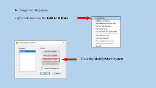
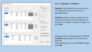
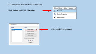
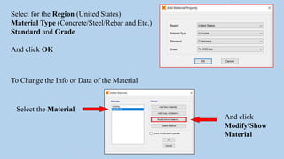

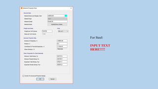


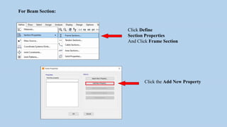


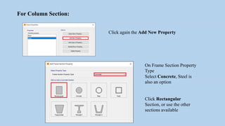


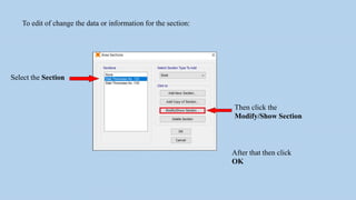


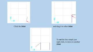


The document outlines a step-by-step process for modeling a building, including defining grids, materials, and sectional properties for structures like beams and slabs. It provides instructions on drawing and replicating elements within a 2D and 3D environment, emphasizing the importance of inputting correct dimensions and properties. Additionally, it details how to model staircase features and manage unwanted elements in the architectural plan.