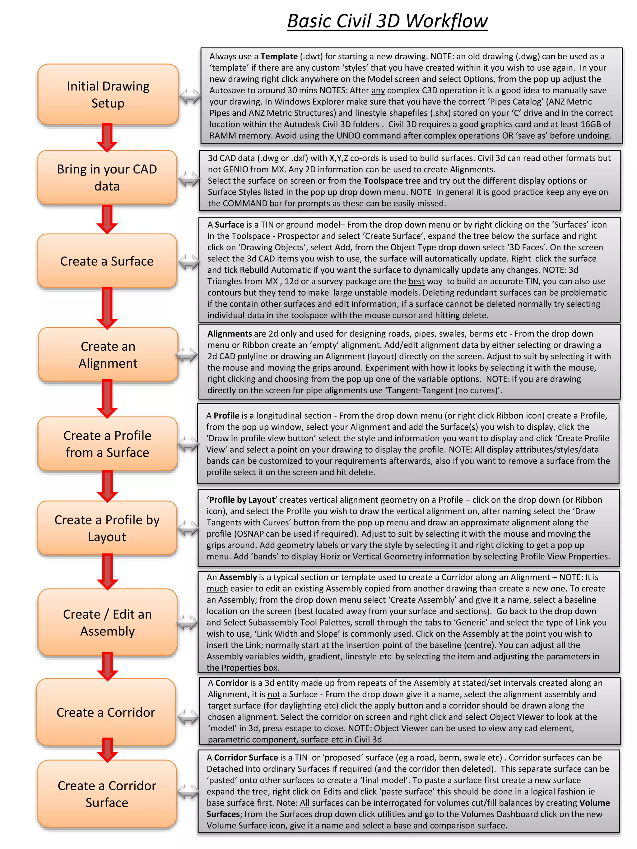
The document provides an overview of the basic Civil 3D workflow including:
- Always starting new drawings from a template and setting autosave to 30 minutes
- Importing 3D CAD data to build surfaces and using alignments for 2D data
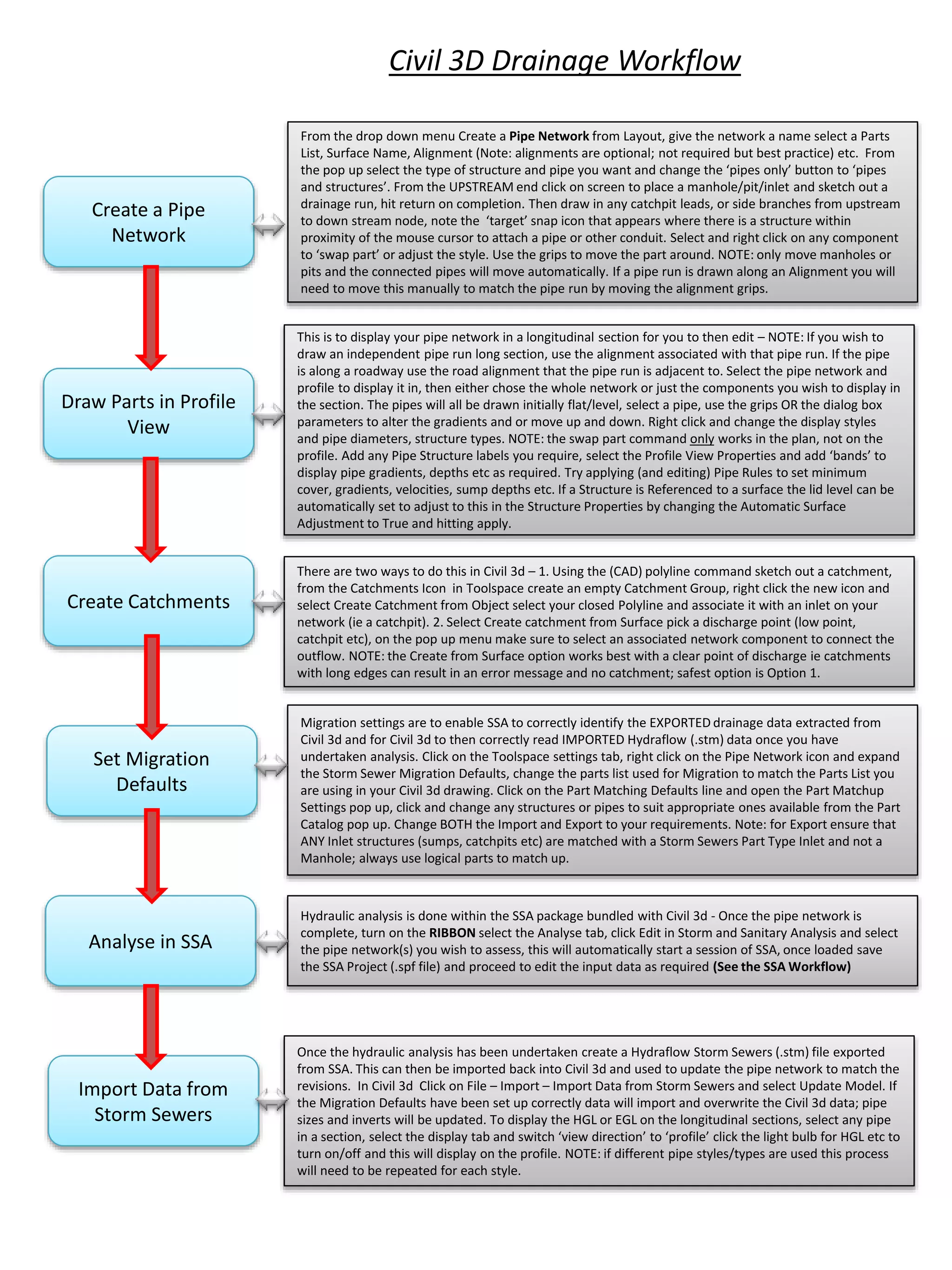
- Creating surfaces, alignments, profiles, assemblies, corridors, and pipe networks
- Setting up storm and sanitary analysis in SSA including inputting IDF curves and editing nodes, links, and catchments
- Analyzing the drainage network in SSA and exporting results back to Civil 3D to update the model