Computer Vision Based Driver Monitoring, Assisting and Grading System for Driving Schools
•
0 likes•9 views

https://www.irjet.net/archives/V10/i6/IRJET-V10I6118.pdf

Recommended
Recommended
More Related Content
Similar to Computer Vision Based Driver Monitoring, Assisting and Grading System for Driving Schools
Similar to Computer Vision Based Driver Monitoring, Assisting and Grading System for Driving Schools (20)
More from IRJET Journal
More from IRJET Journal (20)
Recently uploaded
Recently uploaded (20)
Computer Vision Based Driver Monitoring, Assisting and Grading System for Driving Schools
- 1. © 2023, IRJET | Impact Factor value: 8.226 | ISO 9001:2008 Certified Journal | Page 776 Computer Vision Based Driver Monitoring, Assisting and Grading System for Driving Schools L.D.T.A Srimantha1, R.D.T.M Ranasinghe2, H.A.K.W Jayasekara3, P.A.H.H Pathiraja4 1Department of Computer Systems & Network Engineering Sri Lanka Institute of Information Technology Malabe, Sri Lanka 2Department of Computer Systems & Network Engineering Sri Lanka Institute of Information Technology Malabe, Sri Lanka 3Department of Computer Systems & Network Engineering Sri Lanka Institute of Information Technology Malabe, Sri Lanka 4Department of Computer Systems & Network Engineering Sri Lanka Institute of Information Technology Malabe, Sri Lanka ---------------------------------------------------------------------***--------------------------------------------------------------------- Abstract - Nowadays, the use of vehicles for transportation has increased rapidly. Along with the development of transportation, road systems have been developed. With the increase in the number of vehicles on the roads, vehicle accidents have increased rapidly. Due to this, there is currently a legal system related to the main road systems in countries. Obtaining a driver's license is mandatory in many countries, requiring individuals to pass both a written and practical test, which includes joining a government-registered drivingtrainingschool andreceiving proper training. During the practical exams, examiners generally assess various tasks. A task has several subtasks that must be performed in a specific order. Therefore, more attention is given to these sub-tasks when training drivers. This research proposes an automated driver monitoring, assist, and grading system to enhance the current training process. With the ability of the system to monitor and detect various behaviors, such as observing in the mirrors, using turn signals and horns, and identifying different types of road lines, the system can provide immediate alerts to trainee drivers and generate grading reports at the end of each training session. The proposed system would be effective for driving schools in producing safe and responsible drivers. Key Words: Driver MonitoringSystem,ComputerVision, Image Processing, API, Country-specific regulations, Traffic Rules 1. INTRODUCTION Currently, there are driver monitoring and assistance systems in the world. Thosesystemsaredesignedtomonitor inappropriate driver behaviors and emit immediate warnings. Such as eye movements, head movements, facial expressions, drowsiness detection, vehicle speed, position, etc. But currently, there is no monitoring system for driving in the world. Also, driving schools have the following shortcomings currently. The driving instructor has a heavy workload and a lot of responsibility during a training session. Because they have to give big support to trainee drivers to drive. Instructor should also observe the trainee driver's activities, vehicle safety, and road surroundings. Usually, instructors mark what the trainee is trained to do on a table on a piece of paper, but there is currently no methodology to grade the trainee's activities. Thus, our solution focused on introducing an automated driver monitoring, support, and grading system for driving schools. 1.1 Proposed Driver Monitoring System The major component of the proposed system includes driver identification, face position (left or right) detection, identify different types of road boundary lines (on the center of roads), and detection of blinking taillights of vehicles. Additionally, it includes the detection of honking and turn signal usage. All the above observations are saved in the backend in real time and sent to a web interface via an API (Application Programming Interface). The web interface generates a report at the end of a driving training session. When an individual sits in the driving seat, he or she is to be recognized by a camera (camera 1), which is placed in front and above the seat, only if the trainee has registered with the driving school. This feature is utilized to generate a grading report relevant to an identified person. After that, when starting the training session, the instructor can give commands to do the functions. A microphone is supplied to the instructor. He should provide commands through the microphone. During the driving period, the system continuously monitors the driver. In International Research Journal of Engineering and Technology (IRJET) e-ISSN: 2395-0056 Volume: 10 Issue: 06 | Jun 2023 www.irjet.net p-ISSN: 2395-0072
- 2. International Research Journal of Engineering and Technology (IRJET) e-ISSN: 2395-0056 Volume: 10 Issue: 06 | Jun 2023 www.irjet.net p-ISSN: 2395-0072 © 2023, IRJET | Impact Factor value: 8.226 | ISO 9001:2008 Certified Journal | Page 777 every function, there are sub-functions to be completed and those have a certain order. The instructor’s commands relevant to the functions and sub-functions are presented in Fig-1. Fig-1: Instructor’s commands and sub-functions While driving, the dashboard camera (camera 2)detects two lane lines on the driving track. There are three main types of road boundary lines between two edge lines of the road: broken white lines, single solid lines, and double solid lines. The system can recognize each type of line separately and detect if the vehicle is crossing the line in violationof the rules. One issue we identified was that sometimesdrivers do not see that the turn signal lamp of the nearest front vehicle is blinking. This is because people normally drive while looking away. Therefore, they may not be able to reacttothe turn signals. The issues caused by not seeing turnsignalsare as follows: Drivers wait in vain behind the vehicle in front. Sometimes drivers try to overtake the front vehicle from the right side when the right turn signal is blinking. In such situations, collisions may occur. The actions that we could perform when the vehicle in front flashes a turn signal are, If it is a left turn signal, the driver has a possibility to overtake that vehicle from the right if it is safe to do so. If it is a right turn signal, the driver can overtake that vehicle from the left if it is safe to do so. By recognizing turn signals and performing them correctly, we can avoid collisions and avoid traffic jams. Therefore, this component is introduced to detect blinking turn signal lamps of the vehicle closest to the front and alert immediately the trainee driver. For this part, another separate camera (camera 3) is used. In every function, the driver must look in the mirrors and turn on turn signals. Also, the horn should be sounded when required. The same camera 1 of this system is used to monitor whether the driver is looking in the side mirrors. The camera detects the movement of the driver's face to either side (left or right). Some accessories are utilized for getting inputs from the horn and turn signals. For a trainee driver, all the activities performed are recorded in a text file. Once the training session is terminated, the records are sent to the user interface via the API. Finally, it generates a grading report with marks. 1.1.1 FRAMEWORKS All the components of this system are developed by OpenCV based on the Python language. OpenCV-based driving monitoring systems can enhance road safety by recognizing driver fatigue or distraction. OpenCV (Open- Source Computer Vision Library) is a free and open-source computer vision and machine learning software library that includes several image and video processing algorithmsand tools. Face recognition and vehicle turn signal detection components are developed in PyCharm. PyCharm is a JetBrains cross-platform integrated development environment (IDE) that provides a variety of tools and features to assist programmers in writing efficientandhigh- quality Python code. PyCharm supports a variety of Python frameworks, including Flask. It is beneficial for the above- mentioned components. Flask, a lightweight and flexible Python web framework used for developing online applications and APIs, is utilized in those two components. Head movement detection and road lane line detection components are developed on the VScodedevelopmenttool. VScode from Microsoft is a free and open-sourcecode editor. VScode aims to provide developers with a lightweight and fast environment for writing and debugging code in various programming languages. This includes code completion, debugging tools, and support for various programming languages and frameworks. To extend its functionality, VScode offers numerous extensions and plugins. PyQt5 is deployed for Headmovementdetectionandroad lane line detection components.PyQt5isaPythonbindingfor Qt, a well-known cross-platform GUI toolkit. It provides Python bindings for the Qt library, allowing developers to build powerful graphical user interfaces (GUIs) using the Python programming language. 2. FACE RECOGNITION IN LOW LIGHTCONDITIONS, DARK MODE, AND ANGLE MODE Face recognition is a biometric techniquethatusesfacial traits to identify and verify individuals. It is the technique of automatically detecting and comparing a person's face in a picture or video to a collection of known faces for identifying or verifying that person. Face detection, face
- 3. International Research Journal of Engineering and Technology (IRJET) e-ISSN: 2395-0056 Volume: 10 Issue: 06 | Jun 2023 www.irjet.net p-ISSN: 2395-0072 © 2023, IRJET | Impact Factor value: 8.226 | ISO 9001:2008 Certified Journal | Page 778 alignment, feature extraction,andmatchingareall processes in the face recognition process. The system detects the presence of a face in an image or video using face detection. The technique normalizes the direction and size of the face during face alignment to ensure uniform comparison across different faces. The system examines the featuresoftheface, such as the distance between the eyes or the shape of the nose, and extracts relevant information from them through feature extraction. Finally, for the purpose to identify or validate the individual, the algorithmcomparestheacquiredinformation to a collection of known faces. Access control, law enforcement, Security and surveillance, and consumer electronics are just a few of the possibilities for face recognition technology. It has the potential to revolutionize various industries andfields, butalsoraisesconcernsaround privacy, in this research face recognition was used for trainee drivers’ identification in low light conditions and angle mode [2]. 2.1 Methodology The angle mode Face recognition in driver monitoring systems refers to a face recognition algorithm's ability to reliably identify and recognize a driver's face at various angles and orientations. Because the angle and the distance between the camera and the driver's face andthevisiblesize of the face vary with the driver's height and body size (Fig- 2). This is significant, and the algorithm must be able to reliably identify and recognize the driver's face even under varying settings. The system may then utilize this information to recognize the driver's face even if it is tilted or rotated. Pose estimation techniques canalsobeutilizedto estimate the driver's head position and orientationandalter the recognition algorithm accordingly. Angle-mode facial recognition is vital for driver monitoring systems because it allows the system to accurately identify and recognize the driver and verify that the appropriate safetymeasuresare in place. This system is also convenient for dark mode (Fig-3). Fig -2: Camera installation in a driving school’s vehicle Fig -3: Face recognition in dark mode Fig-4: Face recognition in different angles 3. FACE DIRECTION DETECTION Face movement detection is a component that needs to include in driving monitoring systems. It helps inidentifying the driving candidate’s facial movement when driving. This procedure is going on with image processing but there are some challenges to overcome in this procedure such as low light conditions. Eye tracking, the obstacle of lighting when driving, and nighttime detection of the face in which direction the face heading. This component will help the driving monitoring system by detecting the driving candidate’s face in which direction the face headingtowards to identify that candidate is watching the correct direction when driving. This paper with convey the development of a more efficient and effective face movement detectionforthe safety of the road. This means that the candidate’sfacewhen wants to turn right and left will be detected accordingly. Then this component will help to obtain a clear understanding of the candidate’s reflexes and reactions according to the road signs and conditions. 3.1 Methodology To start the face movement detection procedure, we used image processing using libraries in OpenCV. The box created around the face is assigned red, blue, or greencolors to identify the direction the face is facing. This helps the component detect facial movement. We use the "haarcascade_frontalface_default" model (frontal face detector) and the "haarcascade_profileface" model (right- directed face detector) for this system. "haarcascade_profileface" is a model trained only to recognize faces on the right side. But this system aims to detect the direction of the face (left, right, or forward). The trick used here is to flip the default frames. If an image is detected by a frontal face detector, it shouldbea frontal face. If the default image is detected by the right-directed face
- 4. International Research Journal of Engineering and Technology (IRJET) e-ISSN: 2395-0056 Volume: 10 Issue: 06 | Jun 2023 www.irjet.net p-ISSN: 2395-0072 © 2023, IRJET | Impact Factor value: 8.226 | ISO 9001:2008 Certified Journal | Page 779 detector model, there should be a right-directed face, or if it detects a flipped image, it should be a right-directed face. This is very convenient and supports quick processing for real-time applications. (a) (b) (c) Fig-5: (a) Face turn to the left (b) Frontal face (c) Face turn to the right 4. DIFFERENT TYPES OF ROAD BOUNDARY LINES IDENTIFICATION AND ROAD VIOLATION DETECTION Lane line detection is a crucial component of advanced driverassistancesystemsandself-drivingvehicles. It involves detecting and tracking lane lines on roadstokeep the vehicle in the lane and alert the driver when the vehicle deviates from its lane. Lane line detection is an active research area in computer vision and image processing, but there are still challenges to overcome, such as obstructions, complex lighting and weather conditions, and varying road markings such as solid lines, double lines, and broken lines. This component proposes a driver violation detection system that aims to identify the violation of drivers when they cross the middle line on generic roads. This system employs computer vision to identify separately the three types of middle road lines: broken white lines, single solid white lines, and double solid white lines. The system also detects when a vehicle crosses the middle line, violating the relevant road line rules. This paper intends to contribute to the development of a more efficient and effective lane line detection system for better road safety. Broken Solid White Line (Fig-6 (a)): A broken solid white Line indicates that you can change lanes if it is safe to do so. Single Solid White Line (Fig-7 (b)): A single solid white Line indicates that you cannot pass another vehicle crossing it. The only way you can cross the line is to turn right. Double Solid White Line (Fig-8(c)):Adoublesolidwhite Line indicates that you are not permitted to cross it to pass another vehicle or perform a left turn. The driving rules vary across different countries, making it essential to consider country-specific regulations when designing an effective driver assistance system. This lane line detection component was developed to comply with the left-hand driving rule. However, the proposed system can be readily adapted to suit right-hand driving countries by implementing the appropriate modifications. This flexibility is crucial in ensuring that the system can be applied globally, catering to the diverse driving rules of different countries. (a) (b) (c) Fig-6: The different types of road lines, (a) Broken Solid White Line (b) Single Solid White Line (c) Double Solid White Line 4.1 Methodology To initiate the procedure, the initial step involves defining a function to extract the region of interest (ROI). In this part, we choose the region of interest as a driving lane including two boundary lines. First, the height and width of the provided image are extracted. It then creates a polygon within the picture to represent the ROI. The polygon is generated with numpy's array function, which acceptssome points as input. The points are supplied as tuples of (x,y) coordinates. The function buildsa newnumpyarraywith the same dimensions as the input picture after finding the needed region in the input image after determining the required region in the input image, it generates a new numpy array with the same dimensionsastheinputimage.A mask is then created that includes only the area of interest and fills the polygon region with white. Finally, a mask is applied to mask the included image, producing an image containing only pixels within the specified regionofinterest. This resulting image is returned as the output of the function. The next defined function's goal is to identifyandreturn the lines in the provided input image. An Image is scaled down by 30%. Determine the resized image'snew widthand height. Because a smaller imagerequireslesscalculationand memory. Therefore, it supports quick processing, it is appropriate for real-time applications. It then converts the enlarged image to grayscale and applies a Gaussian blur to reduce the image'sunderstanding.TheCannyEdgedetection method is utilized in this function to detect image edges. Appropriate lower and upper bound values for the hysteresis process utilized in canny edge detection are
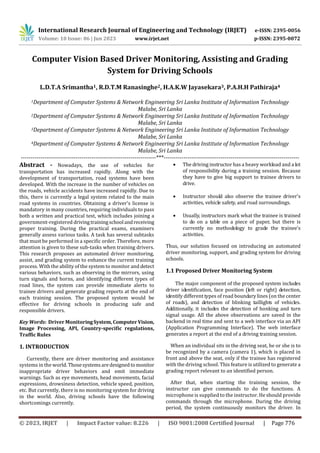
- 5. International Research Journal of Engineering and Technology (IRJET) e-ISSN: 2395-0056 Volume: 10 Issue: 06 | Jun 2023 www.irjet.net p-ISSN: 2395-0072 © 2023, IRJET | Impact Factor value: 8.226 | ISO 9001:2008 Certified Journal | Page 780 defined. It then uses the previously mentioned custom function to extract the region of interest. The contour detection algorithm is then used to discover the contours of the region of interest. Following that, it filters out contours with fewer than 20 pixels in the area and puts the resultant contours in a new tuple. The centroid of each contour in the new tuple is then calculated. Sort the centroids into 20 groups based on their x-coordinates. It then finds the group corresponding to the line by determining whether the x- coordinate of the centroid is within a specified range. Then the line count variable is set to the number of centroids in the line group and the line position variable is set to the x- coordinate of the first centroid in the line group. Finally, a copy of the resized image is created, and the drawing is finished. The copy of the image, the number of lines, and the position of the lines are then output. The previous research that we improved is “Computer VisionBasedRoadLaneLine Detection” [14]. For 640x480 frames, the algorithm speed is around 0.18 s/frame. For 1080x2340 frames, the algorithm speed is around 0.04 s/frame. A test resultofthatresearchis shown in Fig-7 and a test result of our research is shown in Fig-8. Fig-7: Road Lane Line detection in previous research Fig-8: Road Lane Line detection in our research (a) (b) (c) Fig-9: Detecting of main three types of road lines (a) Broken White Line (b) Single Solid White Line (c) Double Solid White Line 5. VEHICLES’ TURN SIGNAL LIGHTS DETECTION Detection of turn light signals is more important for ensuring the safety of the drivers and passengers. when comes to driver training this component can be significantly important, trainee drivers haven't enough experience to identify and respond to theturnsignals appropriately.Entire responsibilities while the training process is transferred to the driving instructor, but he has a heavy workload during this process. Because of that, his small mistake could be able to lead a huge accident. This will assist decrease his responsibilities to some extent. There are so many challenges to detecting turn light signals inreal time.Such as low contrast various lighting conditions, vehicleorientation, and different types of turn taillight systems [16]. The primary objective of the system is to detect the front vehicle's turn signals, identify the direction ofthesignal,and aware the driver via the speaker module. This implementation is intended to contribute to the development of the turn light detection system to ensure safety on the roads. 5.1 Methodology System designed forutilizing a camera moduleplacedon the dashboard of the vehicle to collect real-time video. The system will initially determine color thresholds for turn signal detection from the collected video frame. Then, for improved color segmentation, the BGR color space is converted to the HSV format. To extract the turn signal from the video stream, use the previously determined color thresholds for the HSV frame. Then use the size, shape, and aspect ratio to determine the contours of the turn signal lights. It helps to eliminate the false positives. Finally, given the location of the detected turn signal in the frame, we determine the turn signal’s direction.
- 6. International Research Journal of Engineering and Technology (IRJET) e-ISSN: 2395-0056 Volume: 10 Issue: 06 | Jun 2023 www.irjet.net p-ISSN: 2395-0072 © 2023, IRJET | Impact Factor value: 8.226 | ISO 9001:2008 Certified Journal | Page 781 In this study, using a data set of 150 events, we evaluated a machine-learning model to identify turnsignals. The data set included 23 instances without turn signals,plus 66 left turn signals and 61 right turn signals. Metrics of precision, recall, and F1 score were used to assess model performance. Based on the precision,whichwasdetermined to be 0.756, 75.6% of all events that were predicted to be turn signals were, in fact, turn signals. The model recalled was 0.91176, which means that themodel correctlydetected 91.176% of the actual turn signals in the data set. The F1 score is 0.8266. Fig-10: Detected vehicle turn signal Chart -1: Interested Color Range 6. HONKING AND TURN SIGNAL USING DETECTION Using turn signals and honking is very important while driving. These two tasks are observed and evaluated in the driving license practical test. A pushbuttonisattachedtothe vehicle horn to receive inputs. To receive turn signal inputs, an On-Off-On Double-pole Toggle Switch is installed. These inputs are got from an Arduino mini board. 7. WEB INTERFACE The collected data from the methods mentioned above must be presented in a clear and understandable style. This is accomplished through the use of a user-friendly web interface divided into two sections: the instructor's panel and the data panel. The driving instructor isallowedtoinput voice commands using a microphone, while thelatteracts as a storage space for all pre-definedcandidateactionskeptina text file in the backend. During a training session, the instructor's commands are saved onto thedata panel'stable, and upon termination of the session, the data from the text file is also transferred into the data panel's table. Furthermore, the most recent session state is presented individually on the data panel forconvenientreference.If the driver has performed the relevant sub-activity within one minute after the instructor has given the command for a particular task, the relevant 5 points are awarded. Similarly, 5 marks are given if sub-tasks are done for eachtask.Finally, a grading report is generated for the trainee driver who attended the training session. Fig-11: Driving instructor’s panel. Fig-12: Data panel 8. CONCLUSIONS The latest approach to driver observation, assistance, and grading system for driving schools is presented in this study. Face recognition (person identification); face direction detection (left/right) for whether the driver is looking in the side mirrors; detection of switchON/OFFturn signals; honking detection; separate identification of different types of road boundary lines (the center line of a generic road); and detection of vehicle turn signal flashing with the side (left/right) are all part of the proposed system. To begin, advanced driver monitoring devices have been utilized to monitor the driver's poor or unconscious behaviors, such as falling asleep.Theprimaryfunctionof this system, however, is to monitor driving etiquette and traffic rules. This approach is useful for driving instructors. In
- 7. International Research Journal of Engineering and Technology (IRJET) e-ISSN: 2395-0056 Volume: 10 Issue: 06 | Jun 2023 www.irjet.net p-ISSN: 2395-0072 © 2023, IRJET | Impact Factor value: 8.226 | ISO 9001:2008 Certified Journal | Page 782 addition, trainee drivers benefit because there is no process set up to give them a grading report at the end of each session. Furthermore, even afteranapplicant'strainingterm has ended, this technique may be utilized forself-evaluation. Face identification, roadlane linedetection,andvehiclerear- side turn signal light detection are the three study outcomes of this project. Potential future work will include determining another form of the broken line with solid single lines; detecting several turn signals in one frame; and detecting the direction of the face with eye gaze detection. ACKNOWLEDGEMENT Finally, we want to express our appreciation to our research team for their dedication and hard work. Each member brought unique skills and expertise to the project, and their contributions were vital to its completion. We are fortunate to have such a talented and committed team. REFERENCES [1] IEEE World AI IoT Congress (AIIoT) “Facial Detection in Low Light Environments Using OpenCV” April 15, Available: https://ieeexplore.ieee.org/document/9817372 [Accessed Jan20,2023] [2] University of Science and Technology of China Hefei, China,“ Single-stage Face Detection under Extremely Low- light Conditions” Available: https://openaccess.thecvf.com/content/ICCV2021W/RLQ/p apers/Yu_Single- Stage_Face_Detection_Under_Extremely_Low- Light_Conditions_ICCVW_2021_paper.pdf [Accessed Dec27,2022] [3] Alesia Traichuk, Content Marketing Specialist at Exadel, “Top 9 Facial Recognition Technology Trends of 2022”, Thursday, February 17, 2022,Available:https://www.insightsforprofessionals.com/it /security/facial-recognition-technology-trends-2022 [Accessed Jan2,2023] [4] S. W. Zamir, A. Arora, S. Khan, M. Hayat, F. S. Khan, M.-H. Yang, and L. Shao, “Learning enriched featuresforreal image restoration and enhancement,” 2020. Available: https://www.ecva.net/papers/eccv_2020/papers_ECCV/pap ers/123700494.pdf [Accessed Feb10,2023] [5] F. Lv, Y. Li, and F. Lu, “Attention guided low-light image enhancement with a large scale low-light simulation dataset,”2019,Available: https://arxiv.org/abs/1908.00682 [Accessed Mar12,2023] [6] Haoting Liu, Na Zheng, Yuan Wang, Jiacheng Li, Zhiqiang Zhang, Member, IEEE, Yajie Li, and Jinhui Lan “Development of a face recognition system and its intelligent lighting compensation method for dark-field application”, Available: https://ieeexplore.ieee.org/document/9531007 [Accessed Apr7,2022] [7] Sameer Aqib Hashmi and Mahdy Rahman Chowdhury, “Face Detection in Extreme Conditions: A Machine-learning Approach,” arXiv.org, 2022. Available: https://www.researchgate.net/publication/357926334_Fac e_Detection_in_Extreme_Conditions_A_Machine- learning_Approach [Accessed 20, Apr] [8] H. A. Rowley, S. Baluja, and T. Kanade, “Neural network- based face detection,” IEEE Trans. PatternAnal.Mach.Intell., vol. 20, no. 1, pp. 23–38, Jan. 1998, doi: 10.1109/34.655647. Available: https://ieeexplore.ieee.org/document/655647 [Accessed 18, Apr] [9] Y. Zhu, Youding Zhu, Y. Zhu, K. Fujimura, and K.Fujimura, “Head pose estimation for driver monitoring,” IEEE Intell. Veh. Symp., pp. 501–506, Jun. 2004, doi: 10.1109/ivs.2004.1336434. Available: https://ieeexplore.ieee.org/document/1336434 [Accessed 18, Apr] [10] E. Murphy-Chutorian, A. Doshi, and M.M.Trivedi,“Head Pose Estimation for Driver Assistance Systems: A Robust Algorithm and Experimental Evaluation,” 2007 IEEE Intell. Transp. Syst. Conf., pp. 709–714, Oct. 2007, doi: 10.1109/itsc.2007.4357803. Available: https://ieeexplore.ieee.org/document/4357803 [Accessed 12, Apr] [11] Di Lu and Limin Yan, “Face Detection and Recognition Algorithm in Digital Image Based on Computer Vision Sensor,” J. Sens., vol. 2021, pp. 1–16, Sep. 2021, doi: 10.1155/2021/4796768. Available: https://www.hindawi.com/journals/js/2021/4796768/ [Accessed 2, May] [12] S. K. Satti, K. S. Devi, P. Dhar, and P. Srinivasan, “A machine learning approach for detecting and tracking road boundary lanes,” ICT Express, vol. 7, no. 1, pp. 99–103, Mar. 2021, doi: 10.1016/j.icte.2020.07.007.Available: https://www.sciencedirect.com/science/article/pii/S24059 5952030240X [Accessed 13, Mar] [13] K.-H. Lee et al., “An Attention-based Recurrent Convolutional Network for Vehicle Taillight Recognition,” ArXiv Comput. Vis. Pattern Recognit., Jun. 2019, doi: 10.1109/ivs.2019.8814278. Available: https://ieeexplore.ieee.org/document/8814278 [Accessed 20, Mar] [14] Ashifur Rahman, “Computer Vision Based Road Lane Line Detection,” Soc. Sci. Res. Netw., Jan. 2022, doi: 10.2139/ssrn.4191407. Available: https://papers.ssrn.com/sol3/papers.cfm?abstract_id=4191 407 [Accessed 10, Apr]
- 8. International Research Journal of Engineering and Technology (IRJET) e-ISSN: 2395-0056 Volume: 10 Issue: 06 | Jun 2023 www.irjet.net p-ISSN: 2395-0072 © 2023, IRJET | Impact Factor value: 8.226 | ISO 9001:2008 Certified Journal | Page 783 [15] E. Murphy-Chutorian, A. Doshi, and M.M.Trivedi,“Head Pose Estimation for Driver Assistance Systems: A Robust Algorithm and Experimental Evaluation,” 2007 IEEE Intell. Transp. Syst. Conf., pp. 709–714, Oct. 2007, doi: 10.1109/itsc.2007.4357803. Available: https://ieeexplore.ieee.org/document/4357803 [Accessed 20, Apr] [16] J.-G. Wang et al., “Real-Time Vehicle Signal Lights Recognition with HDR Camera,”2016IEEEInt.Conf.Internet Things IThings IEEE Green Comput. Commun. GreenCom IEEE Cyber Phys. Soc. Comput. CPSCom IEEE Smart Data SmartData, pp. 355–358, Jun. 2016, doi: 10.1109/ithings- greencom-cpscom-smartdata.2016.84. Available : https://ieeexplore.ieee.org/document/7917112 [Accessed 25, Apr] [17] R. O’Malley, E. Jones, and M. Glavin, “Rear-Lamp Vehicle Detection and Tracking in Low-Exposure Color Video for Night Conditions,” IEEE Trans. Intell. Transp. Syst., vol. 11, no. 2, pp. 453–462, Jun. 2010, doi: 10.1109/tits.2010.2045375. Available: https://ieeexplore.ieee.org/abstract/document/5446402 [Accessed 20, Mar] [18] Z. xun Wang and W. Wang, “The research on edge detection algorithm of lane,” Eurasip J.ImageVideoProcess., vol. 2018, no. 1, pp. 1–9, Dec. 2018, doi: 10.1186/s13640- 018-0326-2. Available: https://jivp- eurasipjournals.springeropen.com/articles/10.1186/s13640 -018-0326-2 [Accessed 10, Apr] [19] P. Thammakaroon and P. Tangamchit,“Predictive brake warning at night using taillight characteristic,” 2009 IEEE Int. Symp. Ind. Electron., pp. 217–221, Jul. 2009, doi: 10.1109/isie.2009.5218254. Available: https://ieeexplore.ieee.org/document/5218254 [Accessed 1, May] [20] Yeqiang Qian, Y. Qian, J. M. Dolan, Ming Yang, and M. Yang, “DLT-Net: Joint Detection of Drivable Areas, Lane Lines, and Traffic Objects,” IEEE Trans. Intell. Transp. Syst., vol. 21, no. 11, pp. 4670–4679, Nov. 2020, doi: 10.1109/tits.2019.2943777. Available: https://ieeexplore.ieee.org/document/8937825 [Accessed 10, Mar] [21] W. Farag, Zakaria Saleh, and Z. Saleh, “Road Lane-Lines Detection in Real-Time for Advanced Driving Assistance Systems,” 2018 Int. Conf. Innov. Intell. Inform. Comput. Technol. 3ICT, Nov. 2018, doi: 10.1109/3ict.2018.8855797. Available: https://www.researchgate.net/publication/336255086_Roa d_Lane-Lines_Detection_in_Real- Time_for_Advanced_Driving_Assistance_Systems [Accessed 20, Apr] [22] S. Kamçı, D. Aksu, and M. A. Aydin, “Implementation of Lane Tracking by using Image Processing Techniques in Developed Prototype Autonomous Vehicle,” Int. J.Multimed. Its Appl., vol. 11, no. 6, p. 01, Dec. 2019, doi: 10.5121/ijma.2019.11601. Available: https://aircconline.com/abstract/ijma/v11n6/11619ijma01 .html [Accessed 30, Apr]