What are CompositeStructures?
• General – Any members composed of more
than one material.
• Combination of Steel – Concrete.
Why?
Steel is efficient in tension while concrete is
efficient in compression.
Uses?
Buildings, Bridges
Codes Associated withDesign
• IS 11384 – 1985 – Code of Practice for Composite
Construction in Structural Steel and Concrete.
• This standard deals with the design and construction of
Composite beams ( simply supported ) made up of
structural steel units and cast in-situ concrete.
• Eurocode 4: Design of composite steel and concrete
structures (2004)
• EN 1994-1-1 : General rules and rules for buildings
• EN 1994-1-2 : Structural fire design
• EN 1994-2 : General rules and rules for bridges
5.
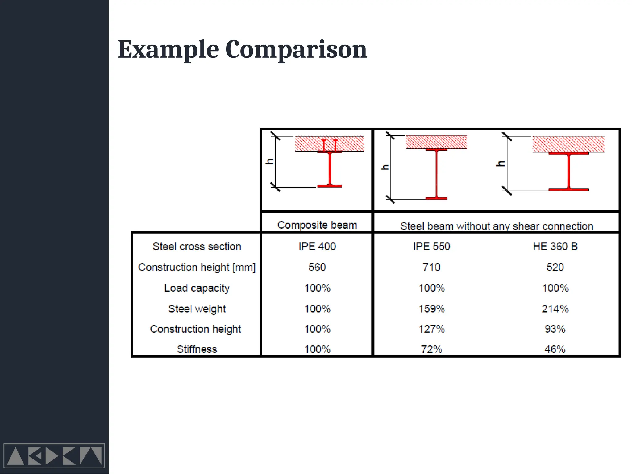
Advantages
• Architectural
• Inaddition to reductions in the dimensions of the beams
• longer spans
• thinner slabs
• Economical
• Reduction of height reduces the total height of the building
• Functionality
• Big Bonus is Fire Safety, Modern steel and composite structures can
provide fire resistance by using principles of reinforced concrete
structures in which the concrete protects the steel because of its high
mass and relatively low thermal conductivity. (IS Codes do not cover
this at all)
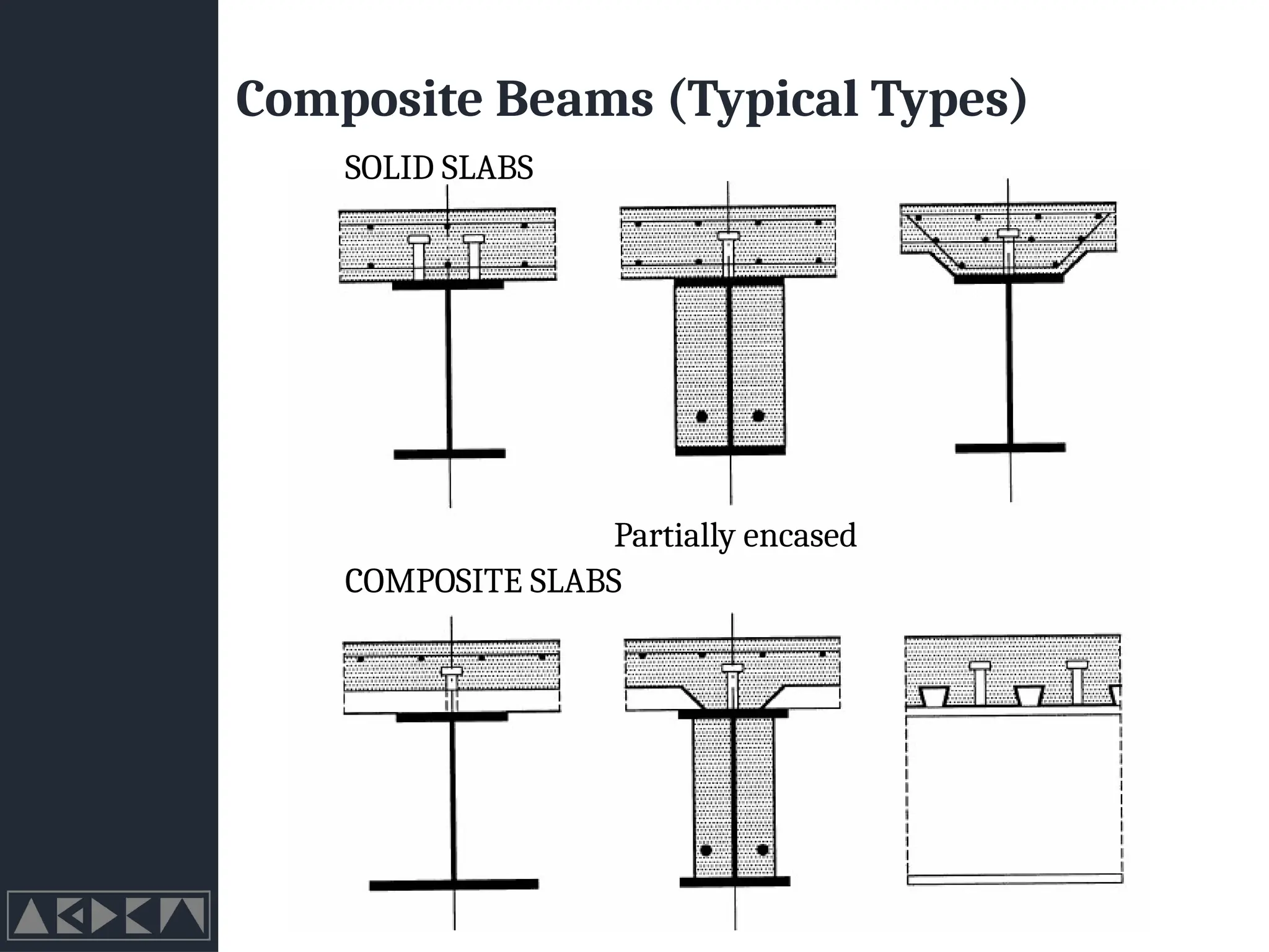
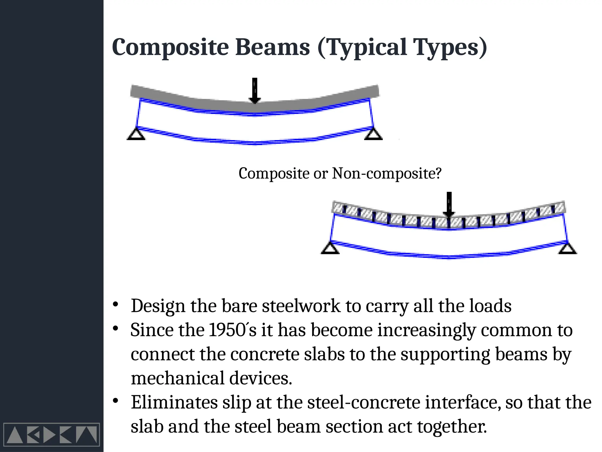
Composite Beams (TypicalTypes)
Composite or Non-composite?
• Design the bare steelwork to carry all the loads
• Since the 1950´s it has become increasingly common to
connect the concrete slabs to the supporting beams by
mechanical devices.
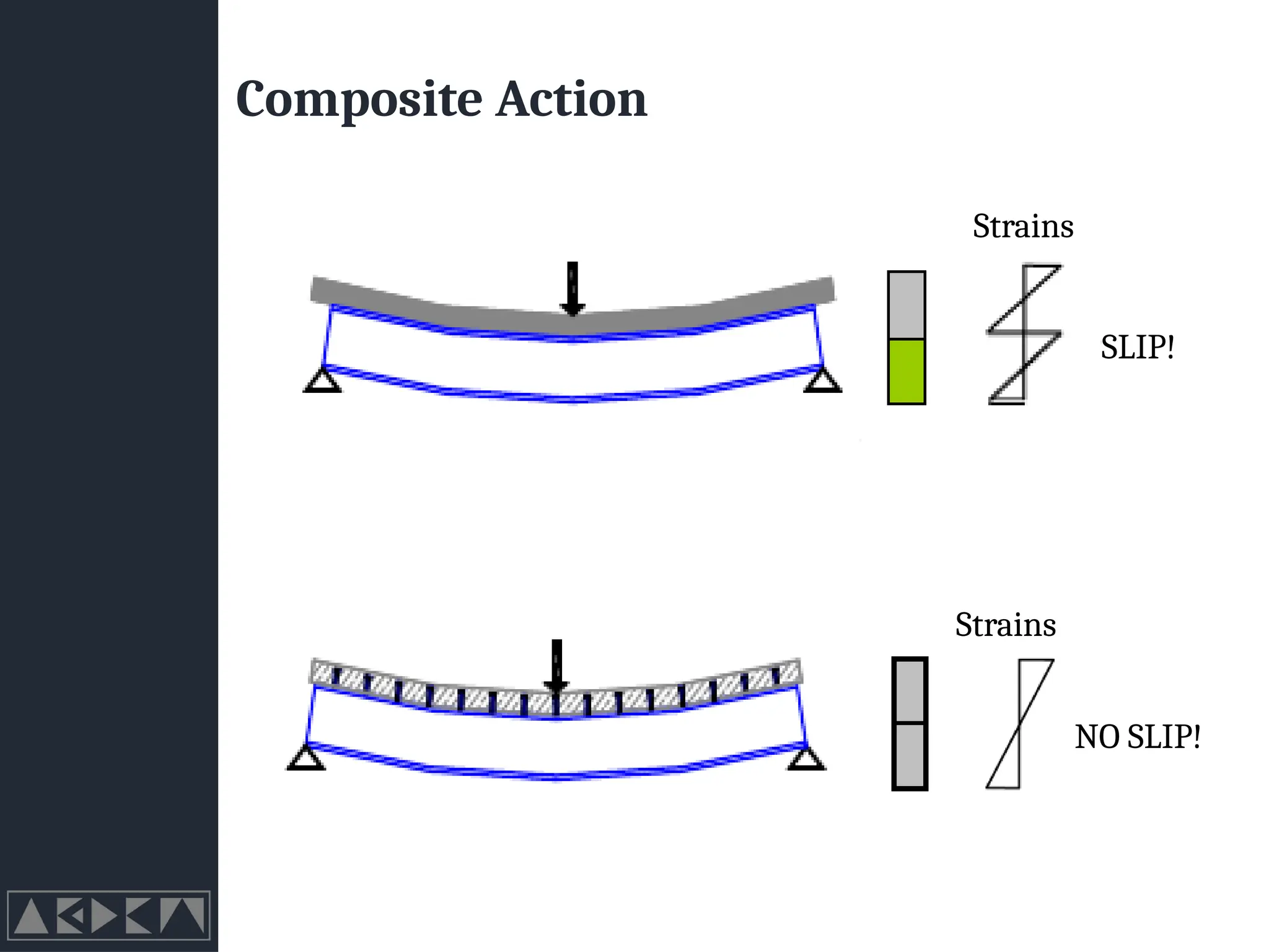
• Eliminates slip at the steel-concrete interface, so that the
slab and the steel beam section act together.
12.
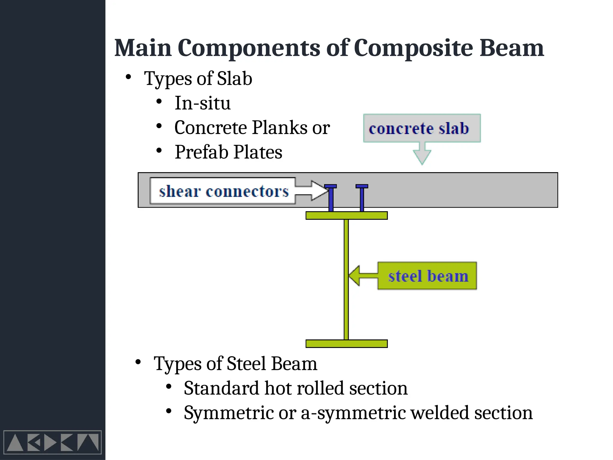
Main Components ofComposite Beam
• Types of Steel Beam
• Standard hot rolled section
• Symmetric or a-symmetric welded section
• Types of Slab
• In-situ
• Concrete Planks or
• Prefab Plates
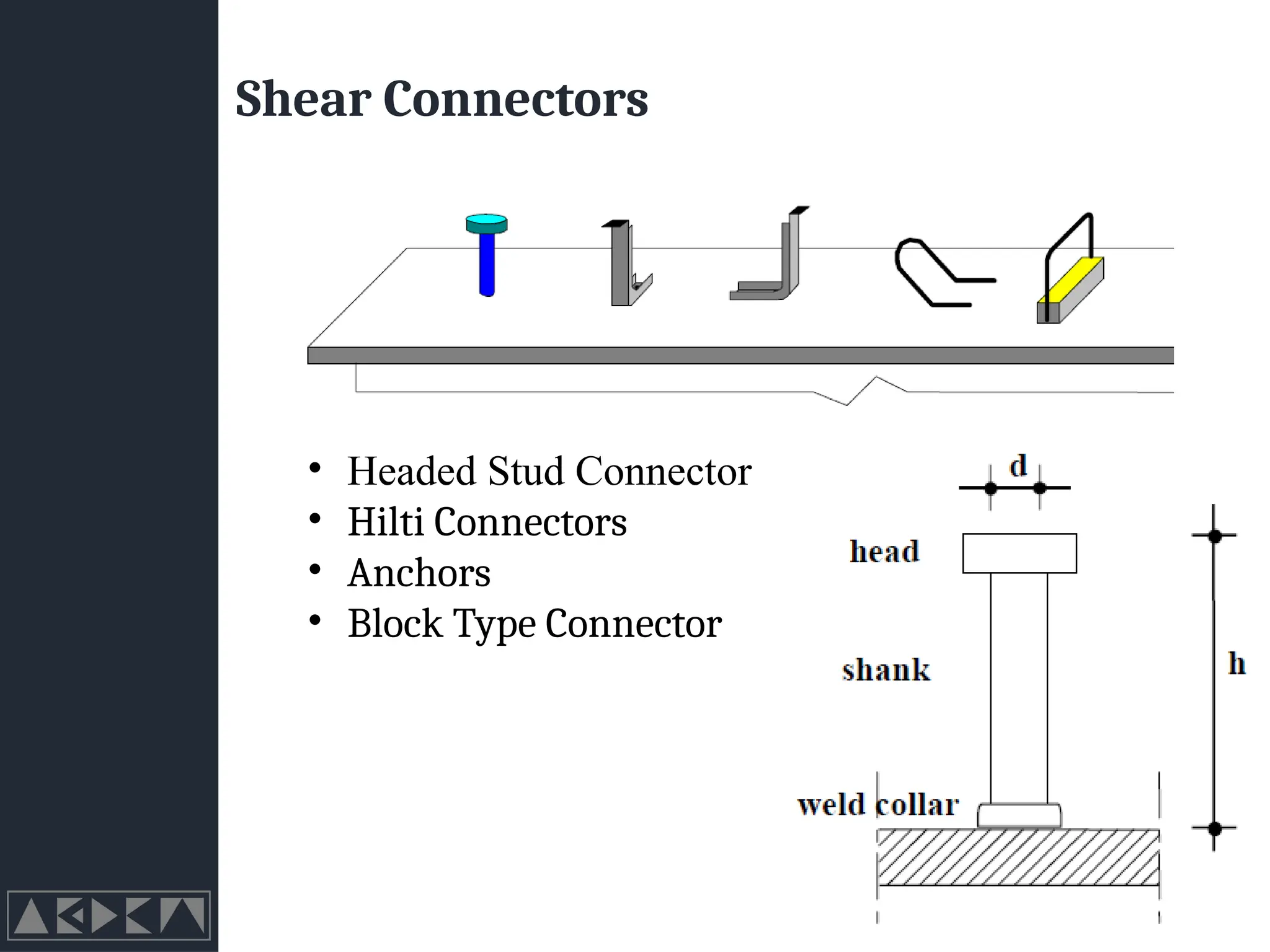
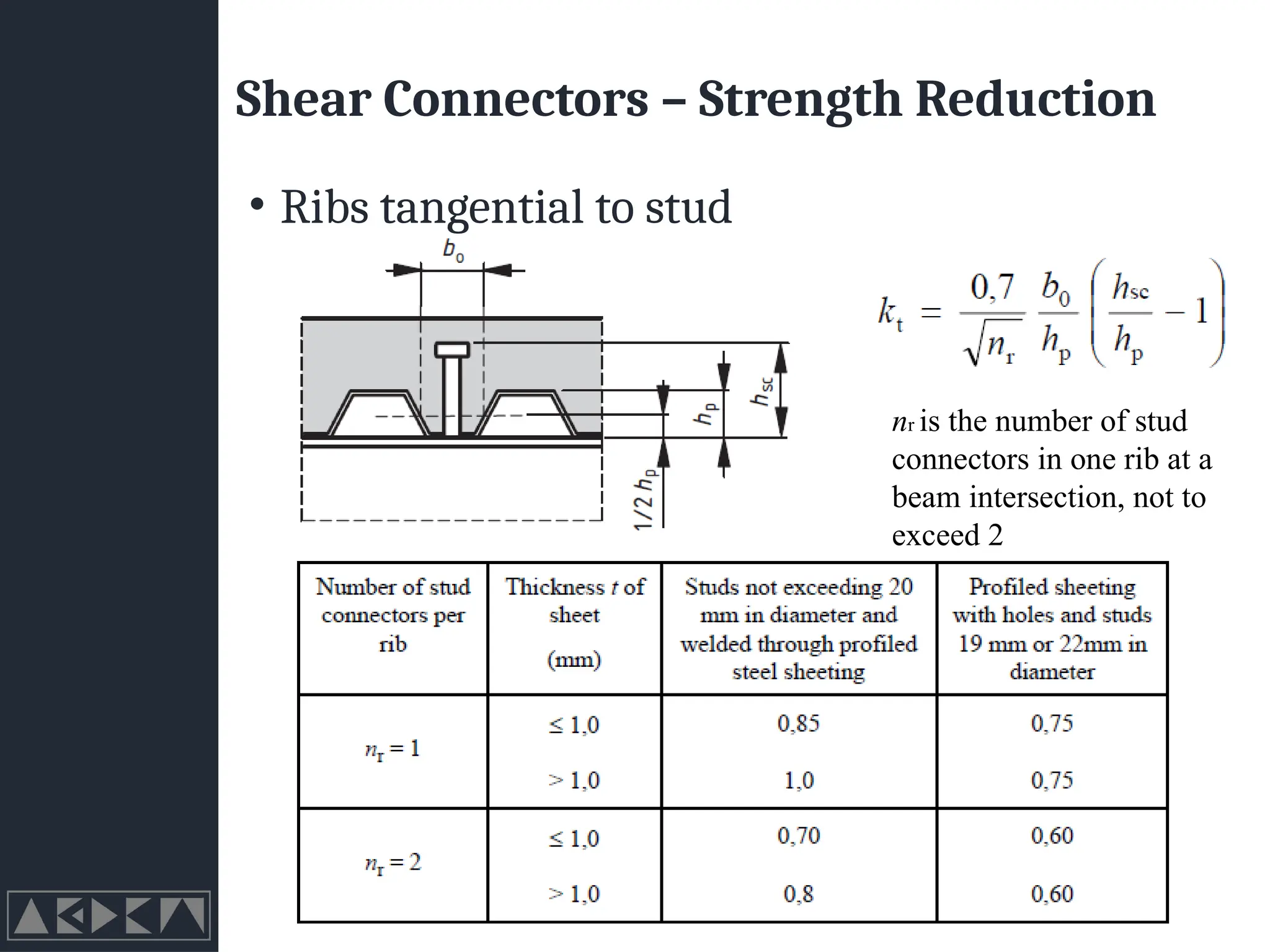
Shear Connectors –Strength Reduction
• Ribs tangential to stud
nr is the number of stud
connectors in one rib at a
beam intersection, not to
exceed 2
23.
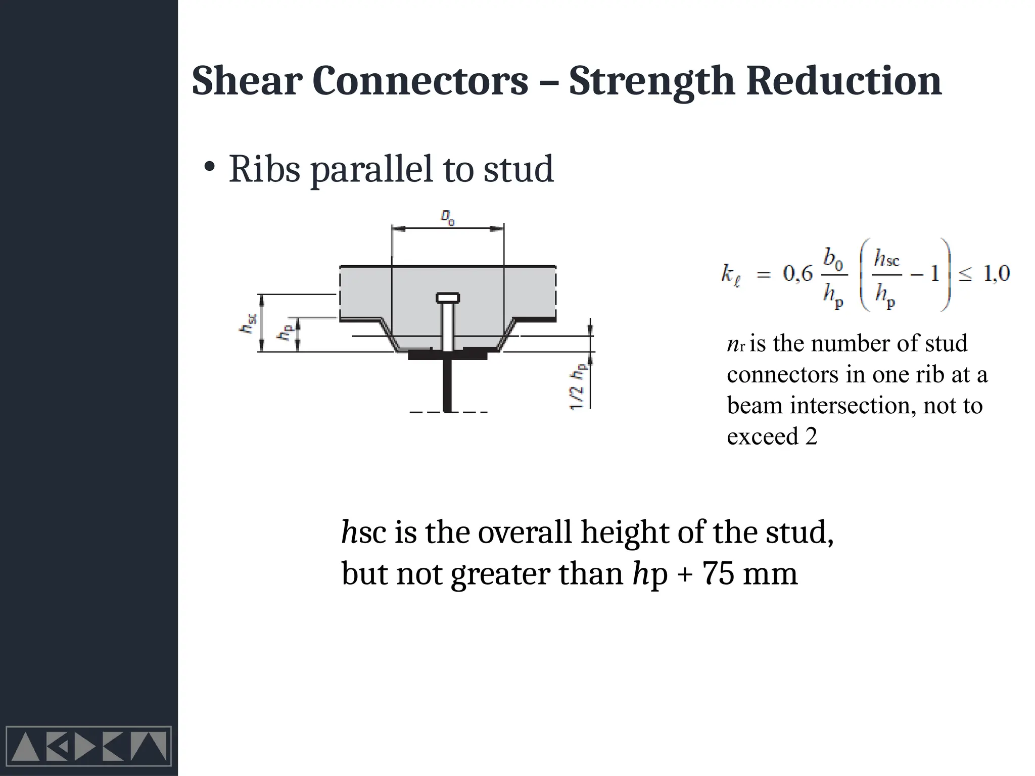
Shear Connectors –Strength Reduction
• Ribs parallel to stud
nr is the number of stud
connectors in one rib at a
beam intersection, not to
exceed 2
hsc is the overall height of the stud,
but not greater than hp + 75 mm


![[BROCHURE] Italy Tour Project | @SlideON](https://cdn.slidesharecdn.com/ss_thumbnails/brochure8-251215152319-2805af68-thumbnail.jpg?width=640&height=640&fit=bounds)


