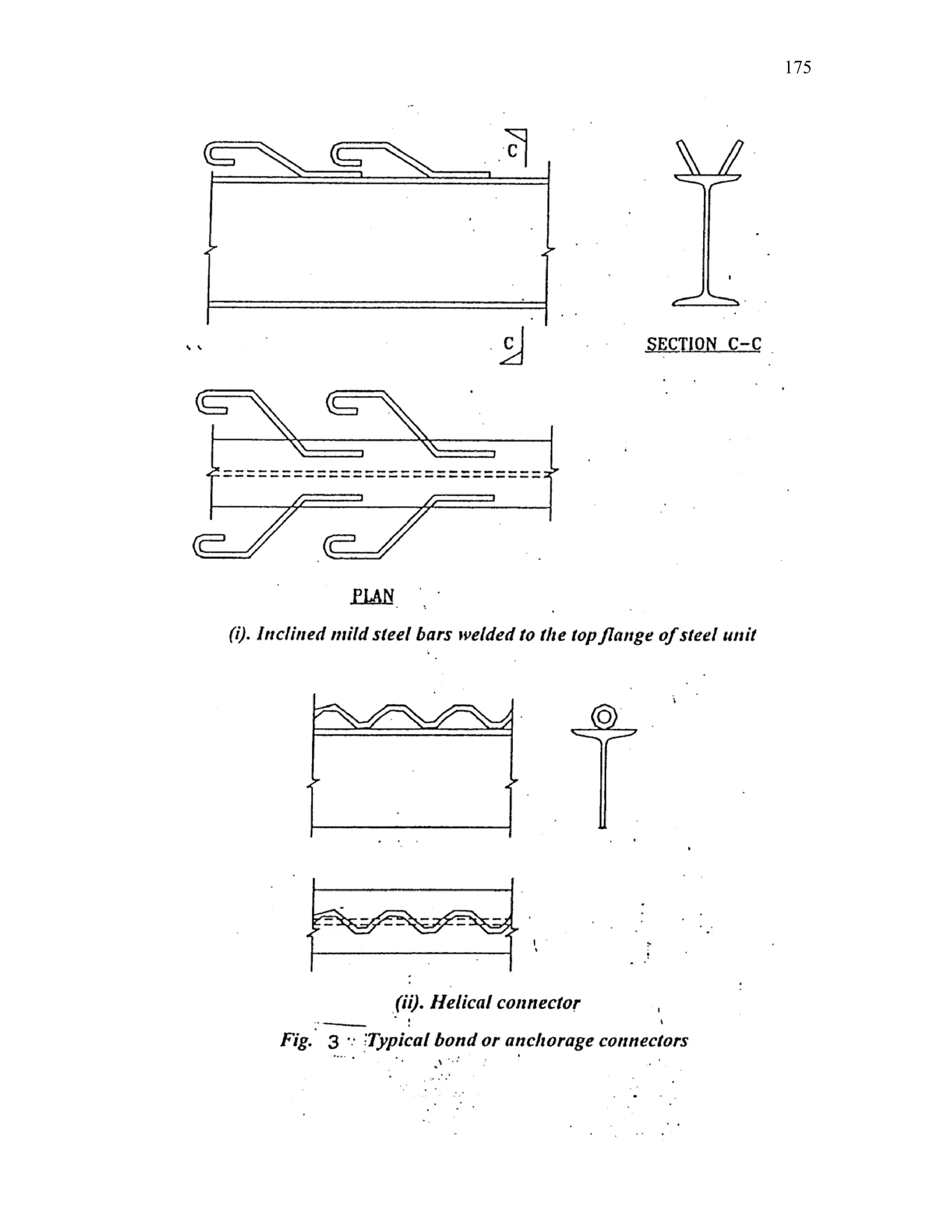
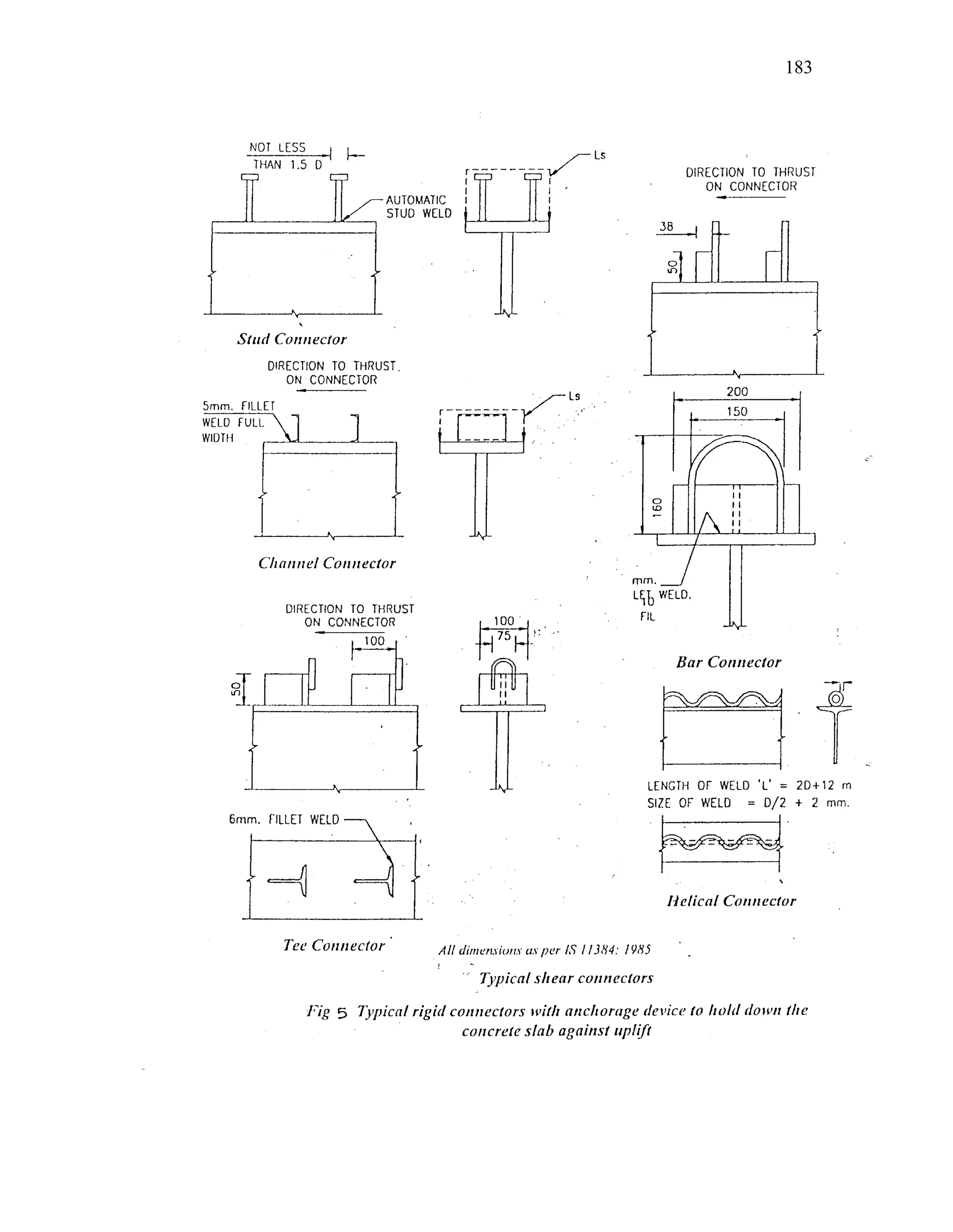
This document discusses steel-concrete composite construction. It describes shear connectors, which provide composite action between steel beams and concrete slabs. There are three main types of shear connectors: rigid connectors made of steel bars or angles that resist shear through bearing pressure; flexible stud connectors that bend and fail through yielding; and bond-type connectors that rely on bond and anchoring. The document discusses the design of shear connectors according to Indian codes IRC 22-1986 and IS 11384-1985, providing methods to calculate the design strength of shear connectors.
![197
A B C
D E F
G H I
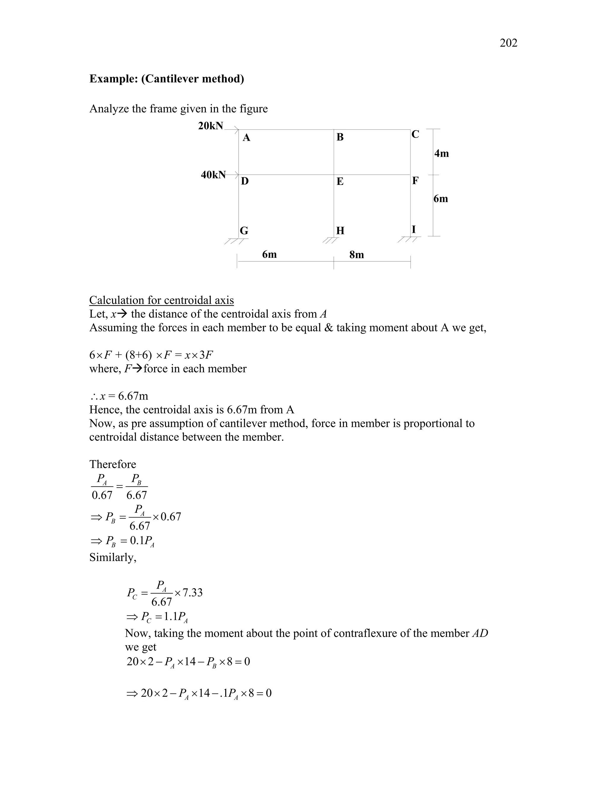
4m
6m
6m 8m
20kN
40kN
• Above assumptions convert indeterminate multi-storey frame to a determinate
structure
Steps involved in analysis of frame:
• Horizontal shears on each level are distributed between columns of that floor
• Moment in each column is equal to column shear multiplied by half the column height
• Girder moments are determined by applying moment equilibrium equation to joints
• Shear in each girder is equal to its moment divided by half the girder length
• Finally, column axial forces are determined by summing up beam shears and other
axial forces at each joint
Example 2: (Portal method)
Analyze the frame given in the figure.
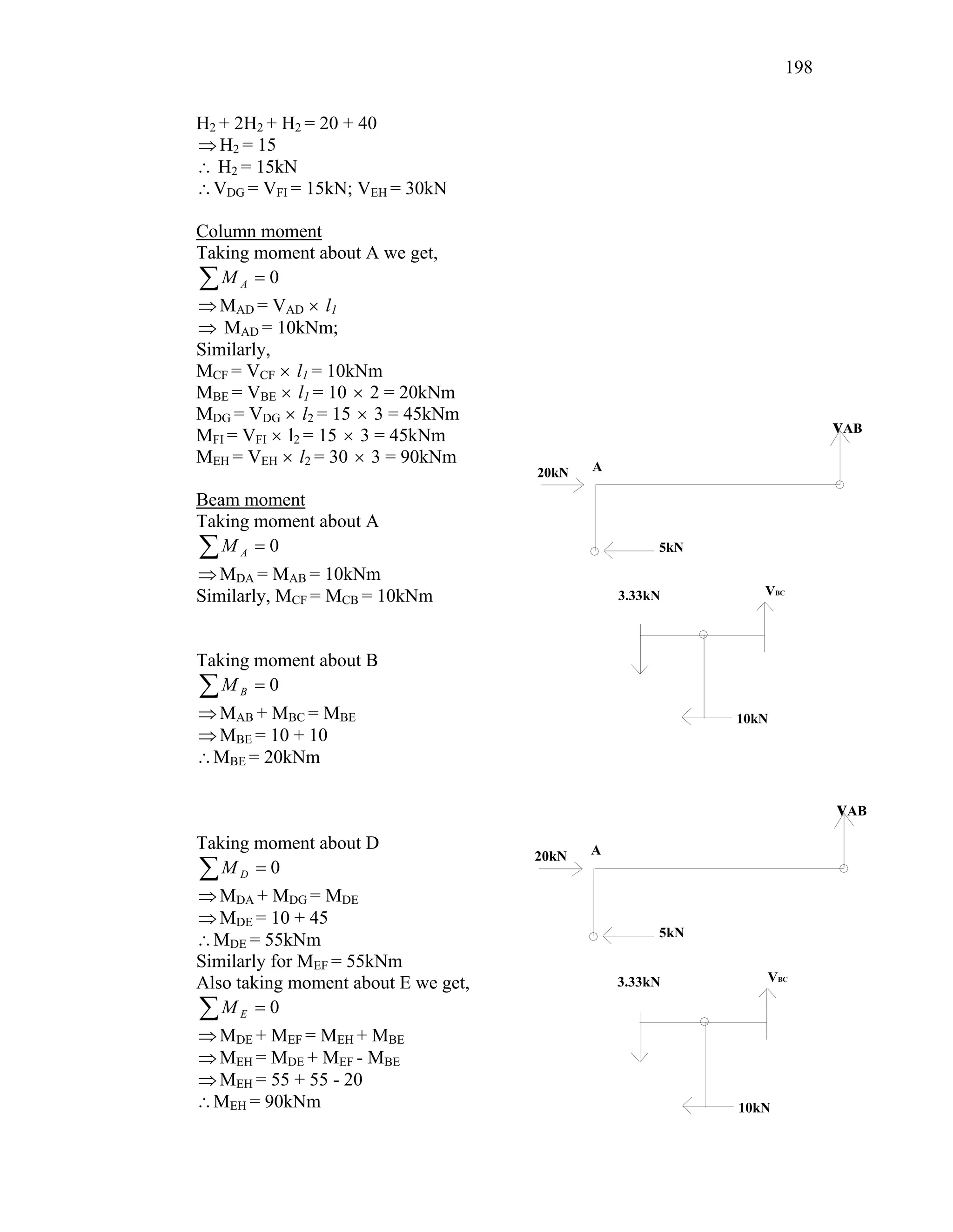
Column shear
Let, H1Æhorizontal shear at the member AD
So,
VAD = VCF = H1; VBE = 2H1 [As per assumption]
So, equating the horizontal forces we get,
H1 + 2H1 + H1 = 20
5
1 =
∴ H kN
∴VAD = VCF = 5kN; VBE =10kN
Let, H2Æhorizontal shear at the member DG
So,
VDG = VFI = H2; VEH = 2H2
Again, equating the horizontal forces we get,](https://image.slidesharecdn.com/compositestructure31-38-220911015532-e4f2815d/75/compositestructure31-38-pdf-38-2048.jpg)