Downloaded 35 times

![Extra Discussion – Interface vs. Class
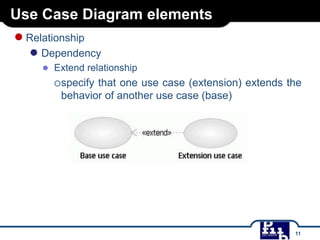
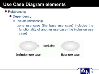
● Implementing Interfaces
●
●
A class uses the implements keyword to implement an interface. The
implements keyword appears in the class declaration following the
extends portion of the declaration.
Example:
/* File name : MammalInt.java */
public class MammalInt implements Animal{
public void eat(){
System.out.println("Mammal eats");
}
public void travel(){
System.out.println("Mammal travels");
}
public int noOfLegs(){
return 0;
}
public static void main(String args[]){
MammalInt m = new MammalInt();
m.eat();
m.travel();
}
}
5](https://image.slidesharecdn.com/bai-giang-uml-11feb14-140212044255-phpapp01/85/Bai-giang-uml-11feb14-5-320.jpg)
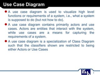
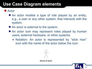
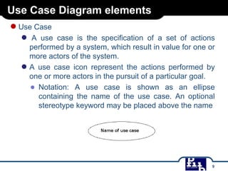
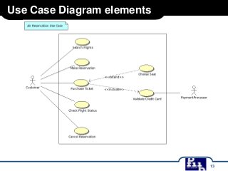

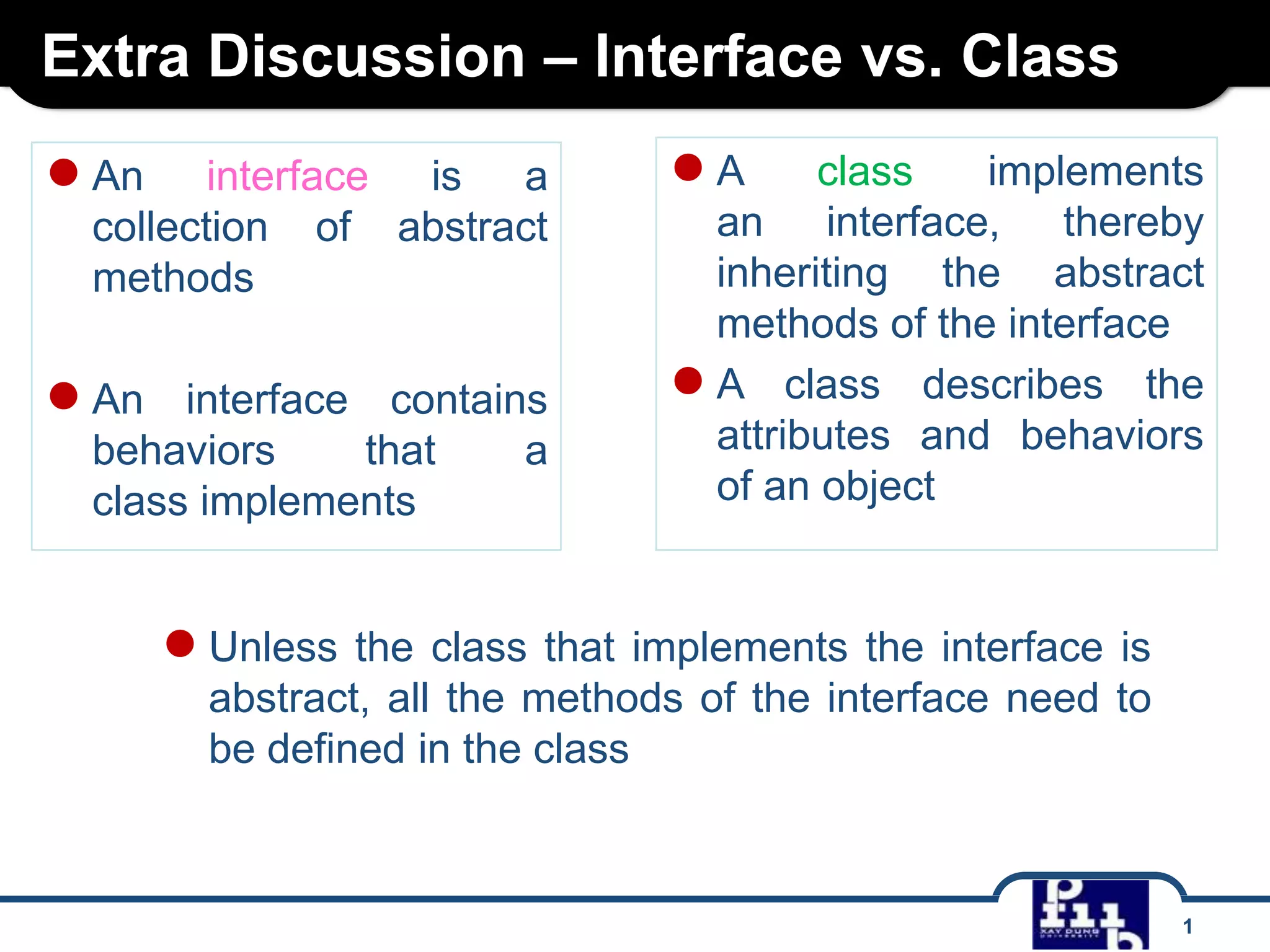
An interface defines a collection of abstract methods that can be implemented by classes. A class implements the interface to inherit its abstract methods and define their behavior. An interface cannot be instantiated on its own but defines common behaviors for other classes to use. A use case diagram models system functions through actors and use cases, where actors represent roles that interact with the system and use cases specify system actions. Relationships like association, dependency, extend and include define interactions between actors and use cases.