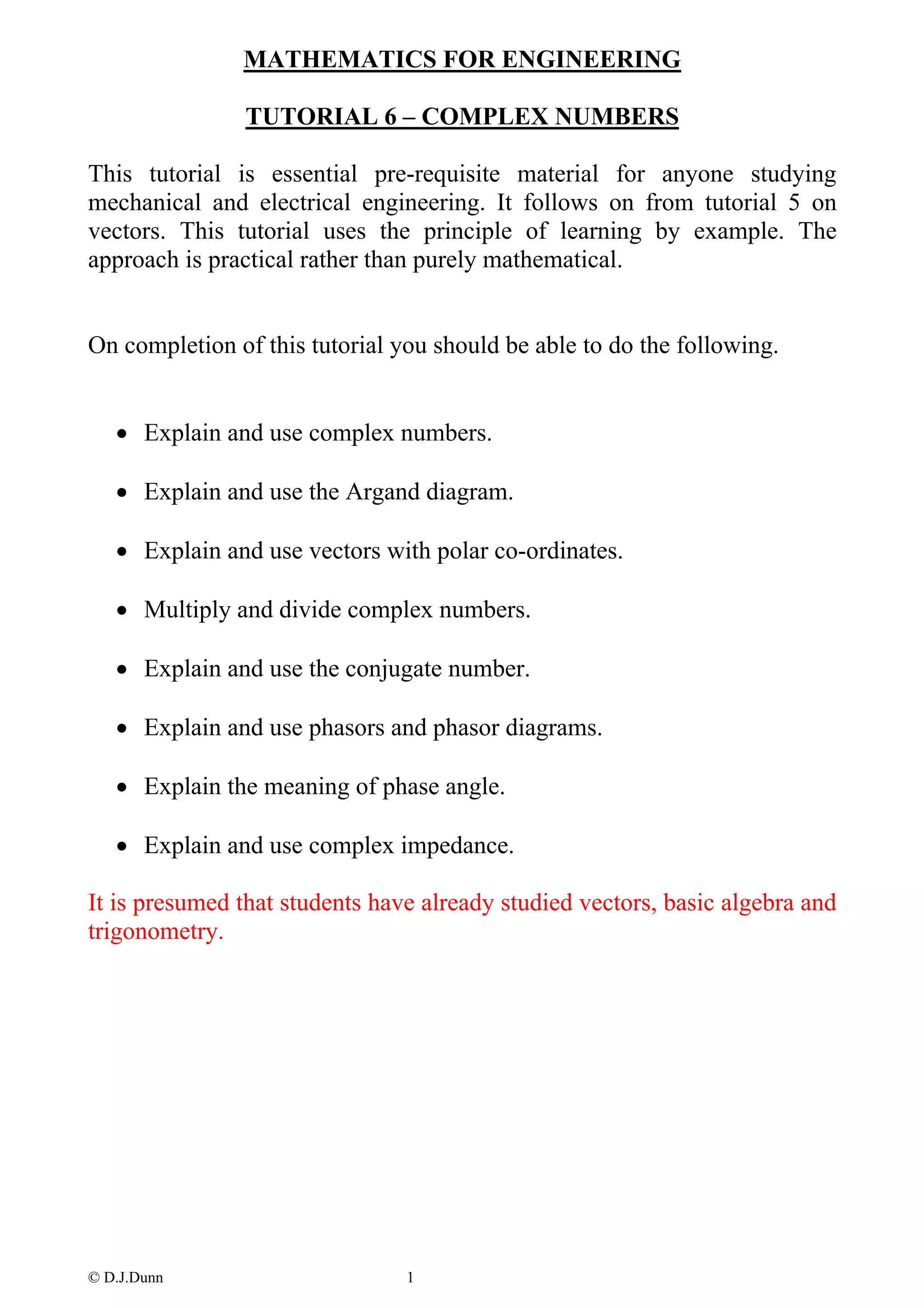
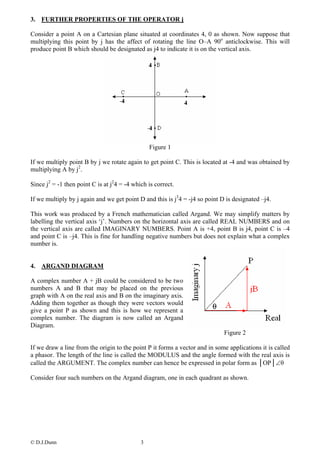
This document provides an overview of complex numbers for engineering students. It begins by explaining how complex numbers are used to represent the square root of negative numbers. It then defines complex numbers as having real and imaginary parts represented by the form a + bj. The rest of the document covers:
- Representing complex numbers on an Argand diagram
- Multiplying and dividing complex numbers using polar coordinates
- Conjugate numbers and their use in multiplication and division
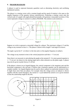
- Phasor diagrams for representing alternating voltages and currents
- Representing impedance as a complex number
The overall aim is to explain key concepts involving complex numbers that are important for mechanical and electrical engineering applications.
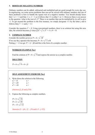
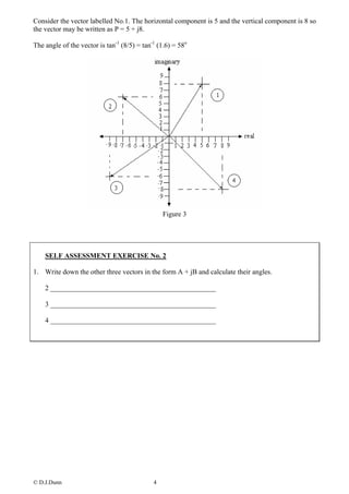
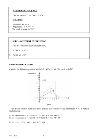
![5. MULTIPLYING COMPLEX NUMBERS
USING POLAR CO-ORDINATES
A complex number may be expressed in polar co-ordinates as follows. Let the Modulus be R and
the argument θ. Consider the two shown. We have R1 ∠θ1 and R2 ∠θ2
Figure 4
We should not confuse the multiplication of vectors (see dot and cross products in the vector
tutorials) with the multiplication of complex numbers.
The real and imaginary co-ordinates are
A1 = R1 cosθ1 B1 = R1 sinθ1
A2 = R2 cosθ2 B2 = R2 sinθ2
The complex number for each vector is:
P1 = R 1cosθ1 + jR 1sinθ1 = R 1{cosθ1 + jsinθ1}
P2 = R 2 cosθ 2 + jR 2 sinθ 2 = R 2 {cosθ 2 + jsinθ 2 }
Multiplying them together and treating j as √-1 we get the following.
P1 x P2 = R 1{cos θ1 + jsin θ1} x R 2 {cos θ 2 + jsin θ 2 }
P1 x P2 = R 1R 2 [cos θ1cos θ 2 + cos θ1 jsin θ 2 + jsin θ1cos θ 2 + jsin θ1 jsin θ 2 ]
[
P1 x P2 = R 1R 2 cos θ1cos θ 2 + j(cos θ1sin θ 2 + sin θ1cos θ 2 ) + j2 sin θ1sin θ 2 ]
P1 x P2 = R 1R 2 [cos θ1cos θ 2 − sin θ1sin θ 2 + j(cos θ1sin θ 2 + sin θ1cos θ 2 )]
P1 x P2 = R 1R 2 [cos(θ1 + θ 2 ) + jsin(θ 2 + θ 2 )]
This is a vector with a length R1R2 and angle θ1+θ2. The rule for multiplying is :
The Modulus is the product of the other Modulii and the argument is the sum of the angles. This
rule applies for any number of vectors multiplied together.
© D.J.Dunn 5](https://image.slidesharecdn.com/complex20numbers-110725012945-phpapp02/85/Complex-20numbers-5-320.jpg)