Download to read offline


![PROJECT 2 |INTERGRATION PROJECT
7BLD 61303 | BUILDING SCIENCE II
2.0 SPACE A : ICT SPACE
Figure 2.0.1 Floor Plan of ICT Space
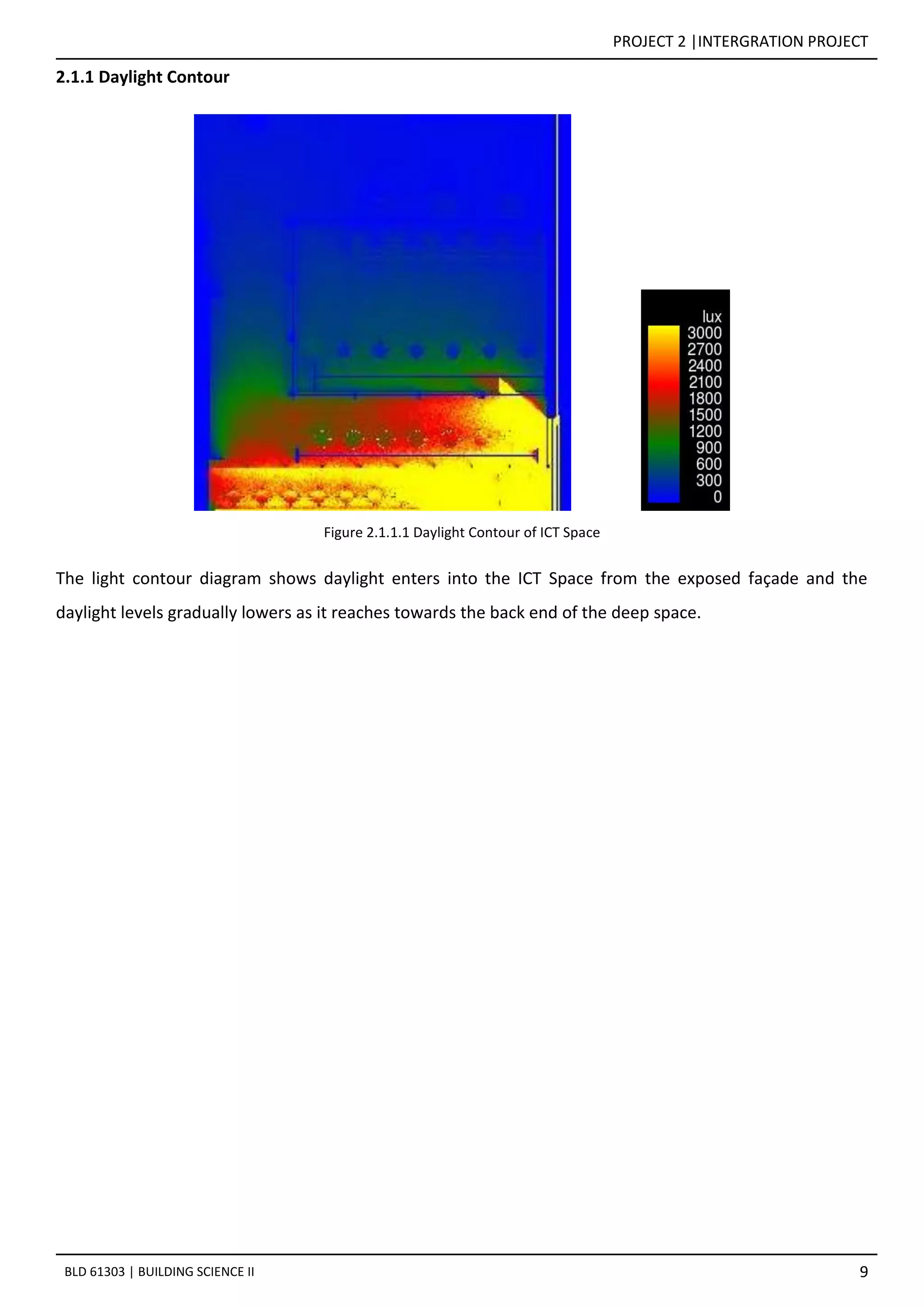
The ICT Space is located at the second floor overlooking the café below, facing the front louvered façade
(east facing). Thus the space is receiving patially coverage of daylight in the morning as shown in Figure
2.0.2.
Figure 2.0.2 [Sectional Perspective A-A] The space is receiving partial daylight from morning sun at 10.00AM
Figure 2.0.3` [Sectional Perspective A-A] The space has no daylight from evening sun at 5.00PM](https://image.slidesharecdn.com/finalreportbsci-170722065231/75/community-lib-bsci-7-2048.jpg)


![PROJECT 2 |INTERGRATION PROJECT
16BLD 61303 | BUILDING SCIENCE II
3.0 SPACE B : QUIET READING SPACE
Figure 3.0.1 Floor Plan of Quiet Reading Space
The enclosed Quiet Reading Space is located on the second floor. This room does not have openings as this
is to maintain the privacy. Thus, this space does not receive daylight as shown in Figure 3.0.2 and Figure
3.0.3.
Figure 3.0.2 [Sectional Perspective B-B] The space has zero daylight throughout the day](https://image.slidesharecdn.com/finalreportbsci-170722065231/75/community-lib-bsci-16-2048.jpg)
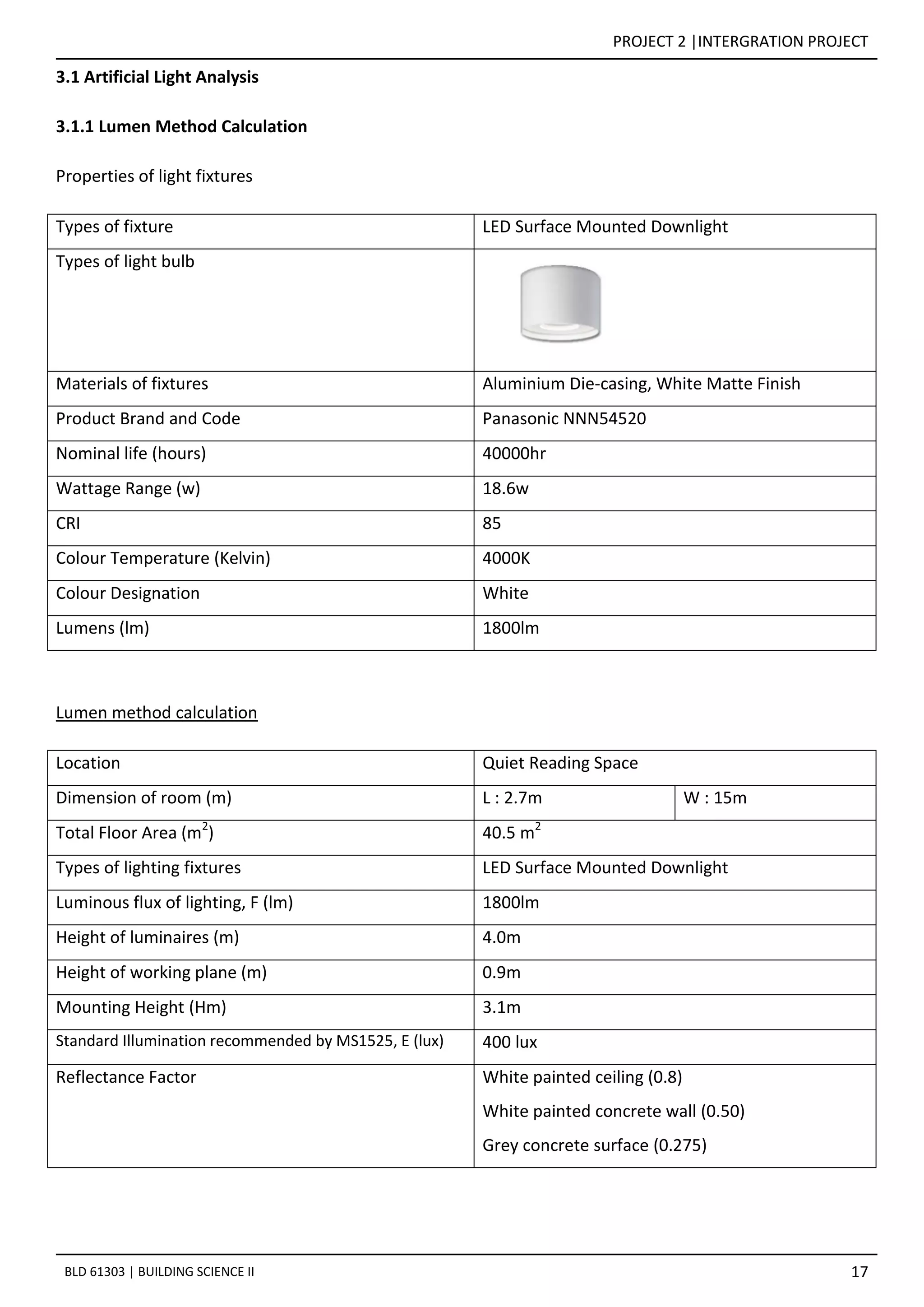
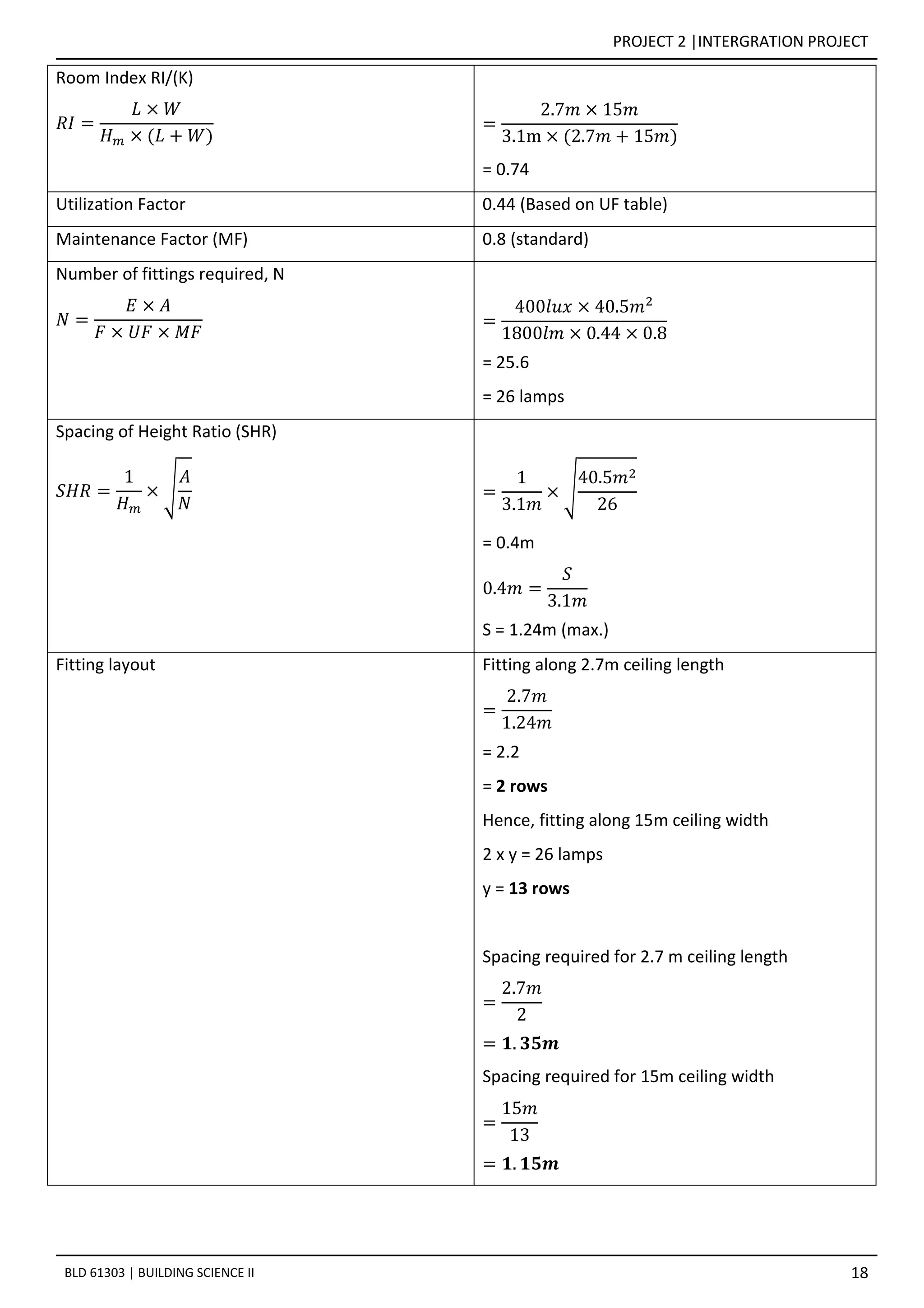


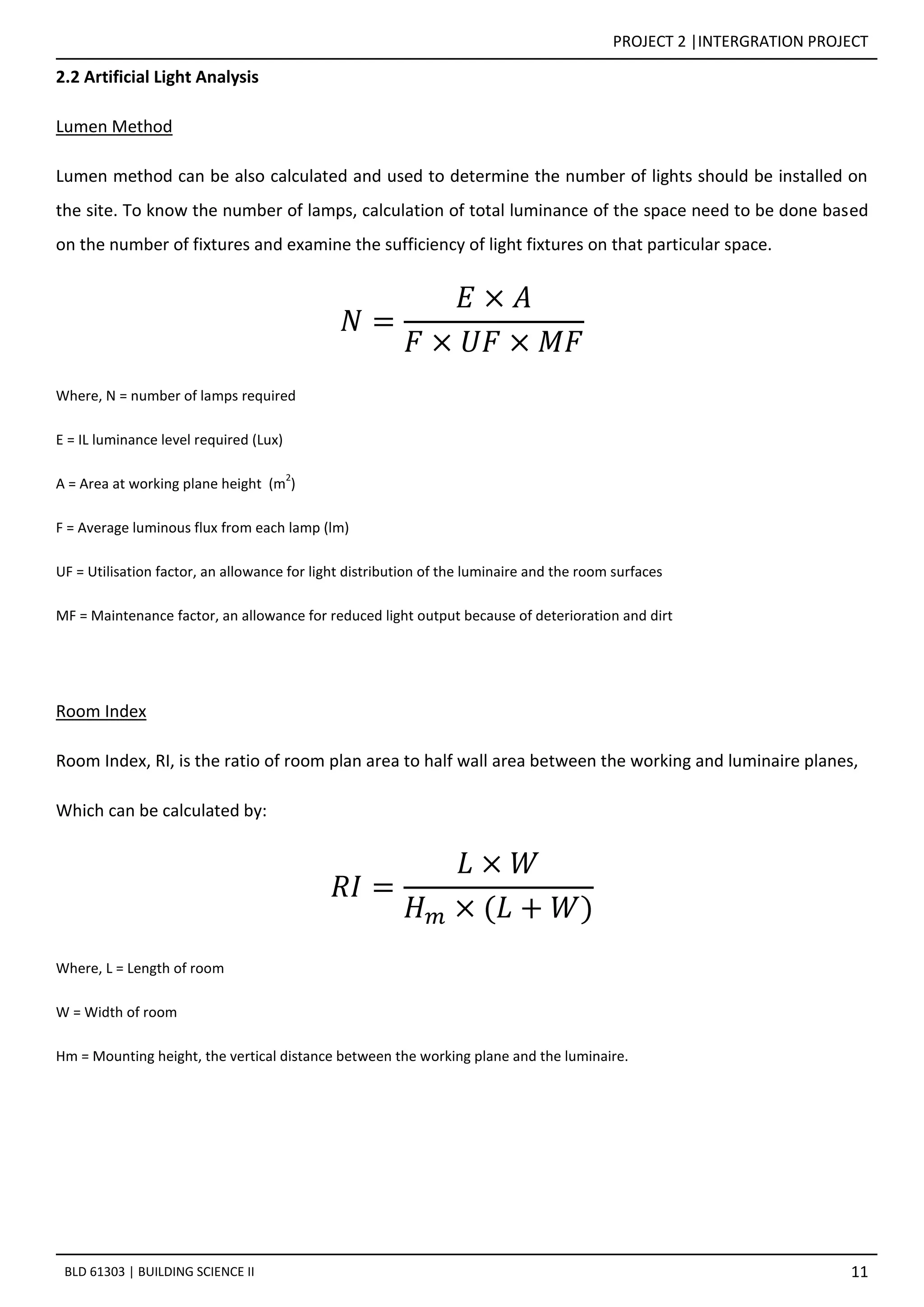
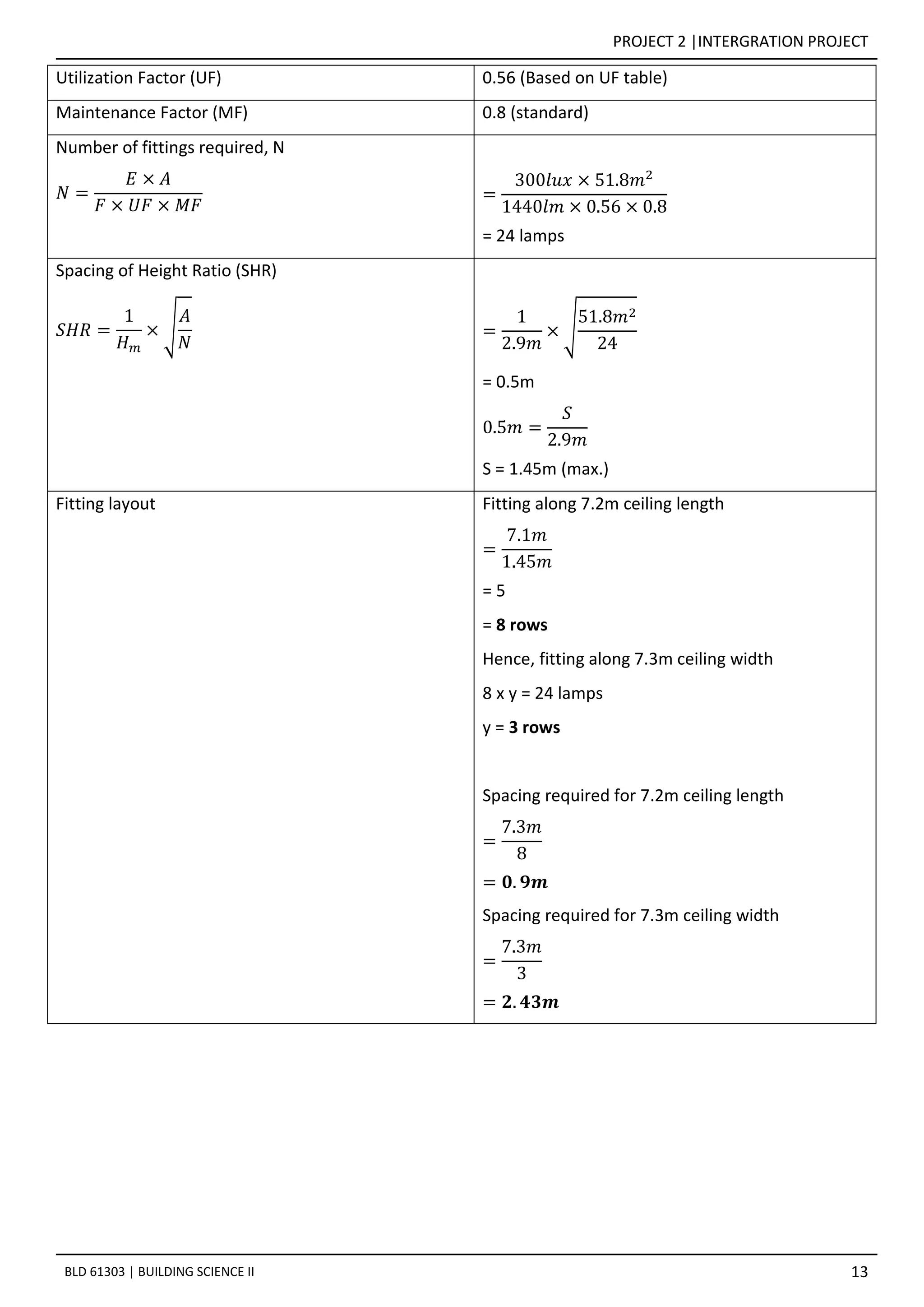
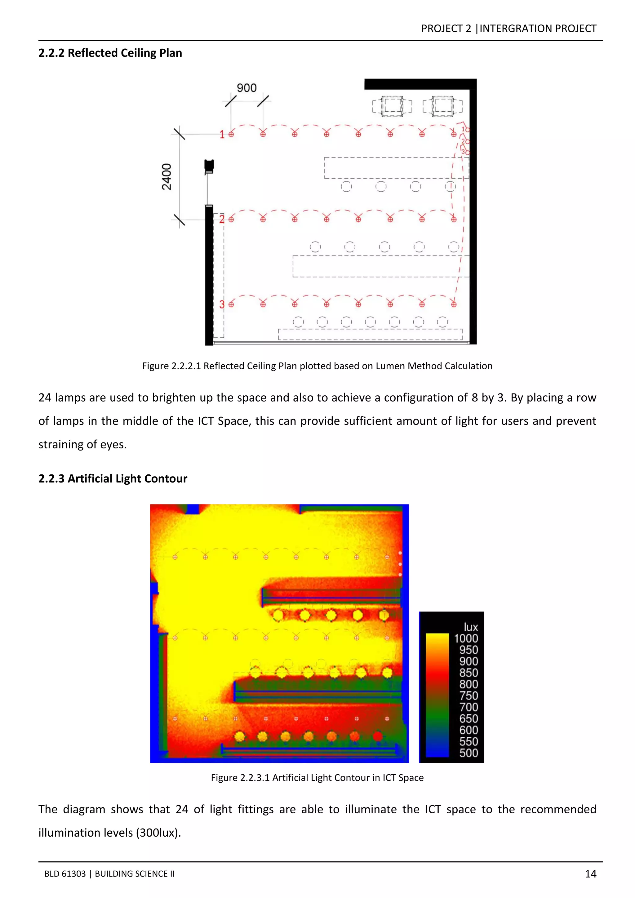
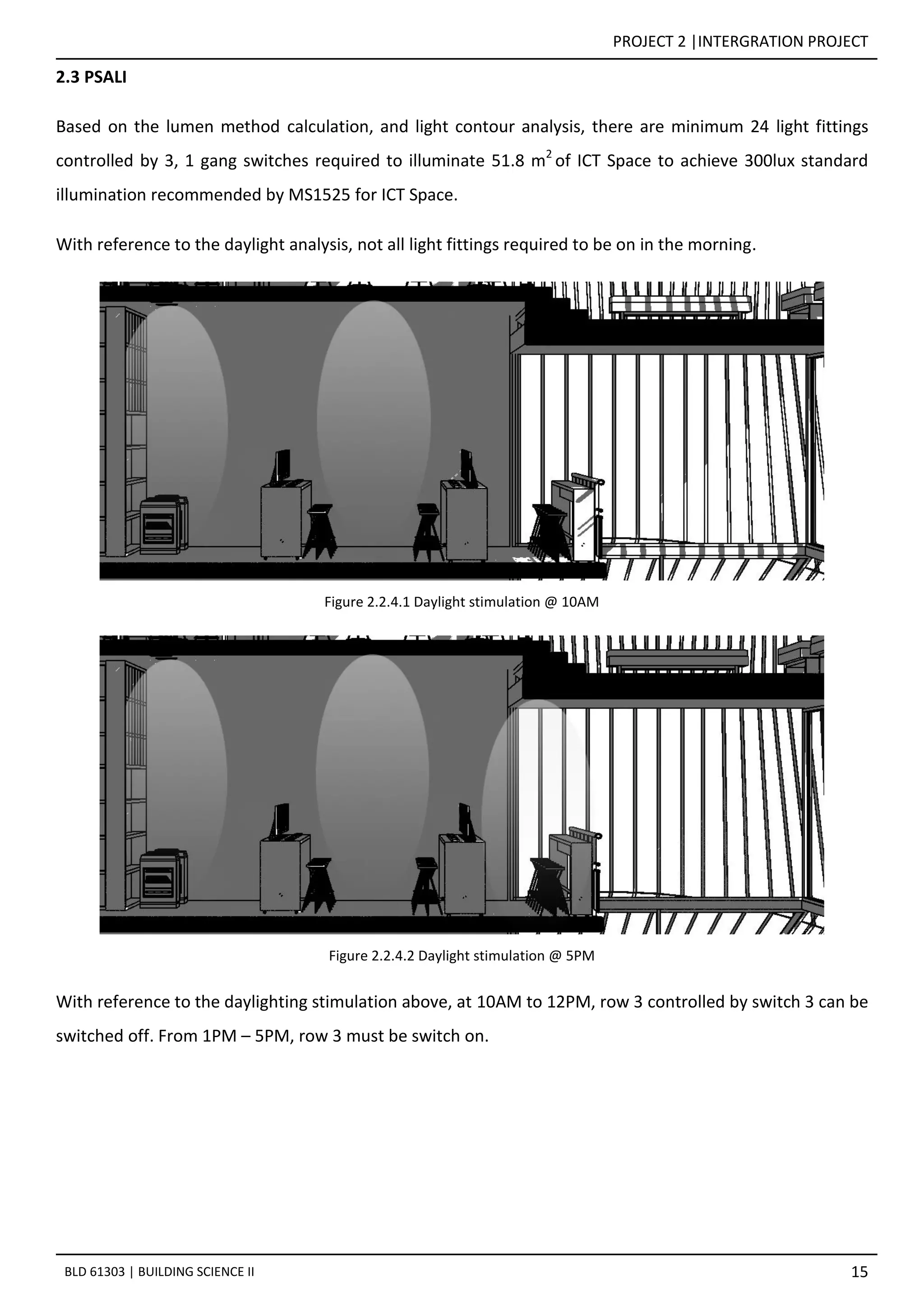
This document provides details on the daylighting and artificial lighting analysis for two spaces within a building: 1. The ICT Space receives some morning daylight but requires 24 LED downlights to meet the 300 lux illumination level standard. Daylight levels are highest near the windows. 2. The enclosed Quiet Reading Space receives no daylight and requires 26 LED downlights arranged in a 13 by 2 configuration to achieve the 400 lux standard. 3. Both spaces' lighting designs were determined using the lumen method and aim to provide sufficient, comfortable illumination.


