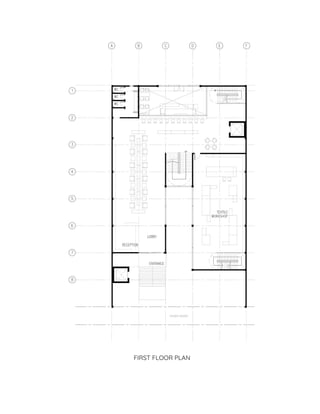
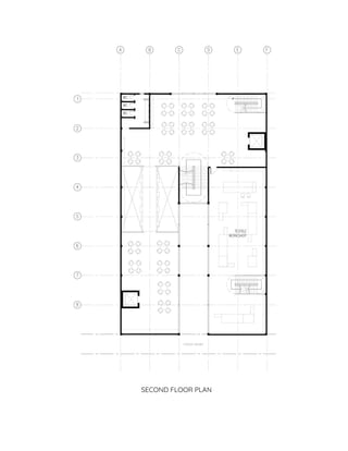
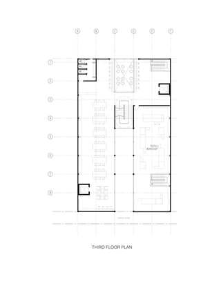
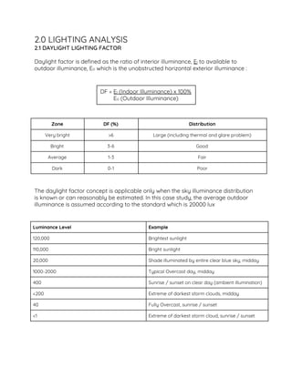
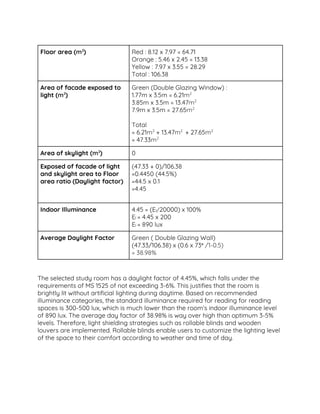
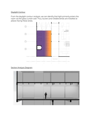
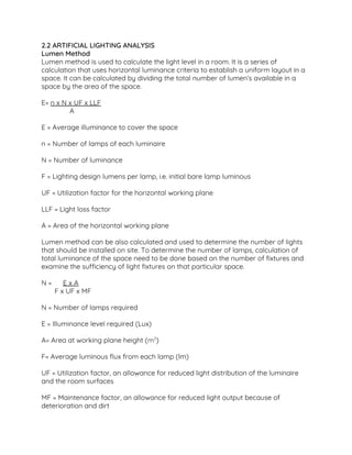
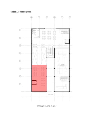
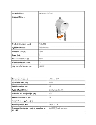
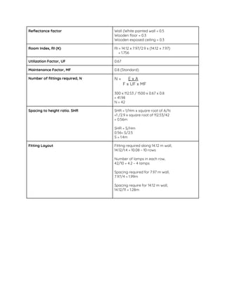
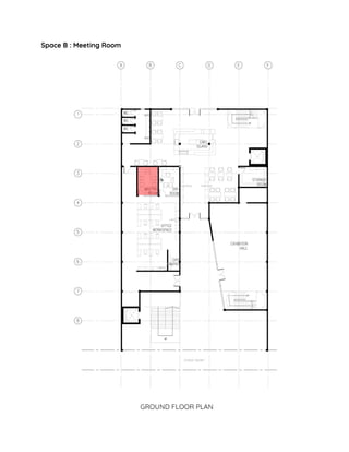
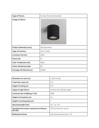
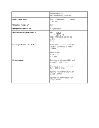
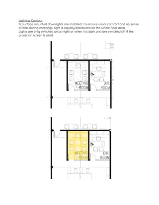
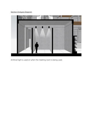
BUILDING SCIENCE II  
PROJECT 2 : INTEGRATION PROJECT 
 
 
AARON CHONG YU HO  
0320270 
 
TUTOR : MR. AZIM SULAIMAN 


1.0 Introduction  
1.1 Objective 
1.2 Project Introduction 
1.3 Floor Plans 
 
2.0 Lighting Analysis  
2.1 Daylight Factor analysis (Space A) 
2.2 Artificial Lighting Analysis (Space A and Space B) 
 
3.0 References  


1.0 INTRODUCTION  
 
1.1 OBJECTIVE  
This project aims to integrate our understanding of lighting design principles in the 
context of our final design project submitted on 27 of June 2017. It encompasses 
artificial lighting systems, daylighting systems and PSALI design strategies.  
 
The site selected is an urban infill in Jalan Besar, Klang. Here we face the challenge 
of tackling the daylighting issues for optimum lighting conditions and visual comfort 
of users. Natural lighting is critical in reducing the carbon footprint by decreasing the 
building’s dependence on artificial lighting. Ensuring sufficient luminance in reading 
spaces. 
 
1.2 PROJECT INTRODUCTION 
 
 
The community library takes up three shop lot spaces, while sandwiched between 
two buildings. My project addresses the issues of lack of softscape and intense heat 
in Jalan Besar. Artificial lighting is utilized on gloomy days or night time.  


1.3 FLOOR PLANS (Scale 1 : 200) 


GROUND FLOOR PLAN 
 
 
FIRST FLOOR PLAN 


SECOND FLOOR PLAN 
 
 
THIRD FLOOR PLAN 
 
2.0 LIGHTING ANALYSIS  
2.1 DAYLIGHT LIGHTING FACTOR 
 
Daylight factor is defined as the ratio of interior illuminance, ​E​i​ to available to 
outdoor illuminance, E​o​ which is the unobstructed horizontal exterior illuminance :  
 
 
DF = ​E​i​ (Indoor Illuminance) x 100% 
E​o​ (Outdoor Illuminance) 
 
 
Zone  DF (%)  Distribution 
Very bright  >6  Large (including thermal and glare problem) 
Bright  3-6  Good 
Average  1-3  Fair 
Dark  0-1  Poor 
 
 
The daylight factor concept is applicable only when the sky illuminance distribution 
is known or can reasonably be estimated. In this case study, the average outdoor 
illuminance is assumed according to the standard which is 20000 lux  
 
 
Luminance Level  Example 
120,000  Brightest sunlight 
110,000  Bright sunlight 
20,000  Shade illuminated by entire clear blue sky, midday 
1000-2000  Typical Overcast day, midday 
400  Sunrise / sunset on clear day (ambient illumination) 
<200  Extreme of darkest storm clouds, midday  
40  Fully Overcast, sunrise / sunset 
<1  Extreme of darkest storm cloud, sunrise / sunset  
 
In side-lit rooms, the maximum daylight factor is near the windows, and it is mainly 
due to the sky component. In the early stages of building design, the average 
daylight factor may be used to assess the adequacy of daylight :  
 
​W ​ ​Tθ 
Average DF = A x (1-R) 
 
W = The area of the windows (​m​2​
) 
 
A = The total area of the internal surfaces (​m​2​
) 
 
T = Glass transmittance corrected for dirt  
 
Θ = Visible sky angle in degrees from the centre of the window  
 
R = Average reflectance of area A 


Space A : Reading Area  


SECOND FLOOR PLAN 
 
Floor area (​m​2​
)  Red : 8.12 x 7.97 = 64.71 
Orange : 5.46 x 2.45 = 13.38  
Yellow : 7.97 x 3.55 = 28.29 
Total : 106.38 
Area of facade exposed to 
light (​m​2​
) 
Green (Double Glazing Window) : 
1.77m x 3.5m = 6.21​m​2
  
3.85m x 3.5m = 13.47​m​2
 
7.9m x 3.5m = 27.65​m​2 
 
Total  
= 6.21​m​2​
+ 13.47​m​2 ​
+ 27.65​m​2 
= 47.33​m​2
  
Area of skylight (​m​2​
)  0  
Exposed of facade of light 
and skylight area to Floor 
area ratio (Daylight factor)  
(47.33 + 0)/106.38 
=0.4450 (44.5%) 
=44.5 x 0.1 
=4.45 
 
Indoor Illuminance  4.45 = (E​i​/​20000) x 100% 
E​i ​= 4.45 x 200 
E​i ​= 890 lux 
Average Daylight Factor  Green ( Double Glazing Wall)  
(47.33/106.38) x (0.6 x 73​° ​/1-0.5) 
= 38.98%  
 
 
The selected study room has a daylight factor of 4.45%, which falls under the 
requirements of MS 1525 of not exceeding 3-6%. This justifies that the room is 
brightly lit without artificial lighting during daytime. Based on recommended 
illuminance categories, the standard illuminance required for reading for reading 
spaces is 300-500 lux, which is much lower than the room’s indoor illuminance level 
of 890 lux. The average day factor of 38.98% is way over high than optimum 3-5% 
levels. Therefore, light shielding strategies such as rollable blinds and wooden 
louvers are implemented. Rollable blinds enable users to customize the lighting level 
of the space to their comfort according to weather and time of day.  


Daylight Contour 
 
From the daylight contour analysis, we can identify that light primarily enters the 
room via the glass curtain wall. Thus, louvers and rollable blinds are installed at 
places facing these areas.  
 
 
Section Analysis Diagram 


2.2 ARTIFICIAL LIGHTING ANALYSIS 
Lumen Method  
Lumen method is used to calculate the light level in a room. It is a series of 
calculation that uses horizontal luminance criteria to establish a uniform layout in a 
space. It can be calculated by dividing the total number of lumen’s available in a 
space by the area of the space.  
 
E= ​n x N x UF x LLF 
A 
 
E = Average illuminance to cover the space  
 
n = Number of lamps of each luminaire 
 
N = Number of luminance  
 
F = Lighting design lumens per lamp, i.e. initial bare lamp luminous  
 
UF = Utilization factor for the horizontal working plane  
 
LLF = Light loss factor  
 
A = Area of the horizontal working plane  
 
Lumen method can be also calculated and used to determine the number of lights 
that should be installed on site. To determine the number of lamps, calculation of 
total luminance of the space need to be done based on the number of fixtures and 
examine the sufficiency of light fixtures on that particular space.  
 
N = ​E x A 
F x UF x MF 
 
N = Number of lamps required  
 
E = Illuminance level required (Lux) 
 
A= Area at working plane height (​m​2​
)  
 
F= Average luminous flux from each lamp (lm) 
 
UF = Utilization factor, an allowance for reduced light distribution of the luminaire 
and the room surfaces  
 
MF = Maintenance factor, an allowance for reduced light output because of 
deterioration and dirt 
Room Index 
 
Room Index. RI, is the ratio of room plan area to half wall area between the working 
and luminaire planes, which can be calculated by :  
 
RI = ​L x W 
Hm x (L + W)  
 
L = Length of room  
 
W = Width of room  
 
M= Mounting height, the vertical distance between the working plane and luminate  
 
Light Loss Factor  
 
Light loss factor allows forecasting of the performance of the system over given 
lifetime to meet the minimum light standards. It is calculated by the following 
formula :  
 
LLF = LLD x LDD x ATF x HE x VE x BF x CD 
 
LLD = Lamp lumen depreciation  
 
LDD = Luminaire dirt depreciation  
 
ATF = Ambient temperature effects  
 
HE = Heat extraction  
 
VE = Voltage effects  
 
BF = Driver and lamps factors  
 
CD = Components depreciation  


Space A : Reading Area  


SECOND FLOOR PLAN 
Type of Fixture  Gravity Light GL 02 
Image of Fixture 
 
Product Dimension (mm)  150 x 350  
Type of luminous   Warm White  
Luminous Flux (lm)  1500 
Power (W)  2 
Color Temperature (K)  5000 
Colour Rendering Index   70 
Average Life Rate (hours)  20000 


Dimension of room (m)  L=14.12 W=7.97 
Total floor area (​m​2​
)  112.53 
Height of ceiling (m)  3.9 
Types of Light fixture   Gravity Light GL 02 
Luminous flux of lighting, F (lm)  1500 
Height of luminaires (m)  3.9 
Height if working plane (m)  1 
Mounting height (Hm)  3.9 - 1.0 = 2.9 
Standard Illumination required according to 
MS 1525 
300-500 (Reading rooms) 
Reflectance factor   Wall (White painted wall = 0.5 
Wooden floor = 0.3  
Wooden exposed ceiling = 0.3  
Room Index, RI (K)  RI = 14.12 x 7.97/2.9 x (14.12 + 7.97)  
= 1.756 
Utilization Factor, UF   0.67 
Maintenance Factor, MF   0.8 (Standard) 
Number of fittings required, N   N = ​E x A 
F x UF x MF 
 
300 x 112.53 / 1500 x 0.67 x 0.8 
= 41.98 
N = 42 
Spacing to height ratio. SHR  SHR = 1/Hm x square root of A/N 
=1 /2.9 x square root of 112.53/42 
= 0.56m 
 
SHR = S/Hm 
0.56= S/2.5  
S = 1.4m 
Fitting Layout   Fitting required along 14.12 m wall,  
14.12/1.4 = 10.08 ~ 10 rows 
 
Number of lamps in each row,  
42/10 = 4.2 ~ 4 lamps  
 
Spacing required for 7.97 m wall,  
7.97/4 = 1.99m  
 
Spacing require for 14.12 m wall,  
14.12/11 = 1.28m 


Lighting Fittings Spacial Diagram  
 
Gravity lamps are gravity-powered for most of its energy source. It uses a bag filled 
with rocks attached to a cord, which slowly descends similar to the weigh driver of a 
cuckoo clock. This action powers the light for 30 minutes.  
Therefore, its implementation saves up a sum of energy, lowering the library’s 
carbon footprint and energy consumption.  


Lighting Contour 


During daytime, mere daylight is sufficient in illuminating the room, albeit blinds are 
required to reduce glare that jeopardizes user comfort.  
 
 
Gravity lamps are a new technology advancement and thus, its luminous flux is still 
relatively low with today’s technology. Thus, 38 lamps are installed instead of 40 
recommended by calculations to ensure that light switches are within user reach 
from various places without requiring much mobility.  
Section Analysis Diagram 


Users pull the switches whenever they feel that light is needed. In the diagram 
above, the user switches on one row of lamps from left to right.  


Space B : Meeting Room 


GROUND FLOOR PLAN 
 
Type of Fixture  Surface Mounted Downlight 
Image of Fixture 
 
Product Dimension (mm)  200 (diameter) 
Type of luminous   Warm White  
Luminous Flux (lm)  2000 
Power (W)  10 
Color Temperature (K)  4000 
Colour Rendering Index   80 
Average Life Rate (hours)  20000 
 
 
Dimension of room (m)  L=3.95 W=2.82 
Total floor area (​m​2​
)  11.14 
Height of ceiling (m)  4.75 
Types of Light fixture   Surface Mounted Downlight 
Luminous flux of lighting, F (lm)  2000 
Height of luminaires (m)  4.0 
Height if working plane (m)  1 
Mounting height (Hm)  4.0 - 1.0 = 3.0 
Standard Illumination required according to 
MS 1525 
750 (Conference rooms) 
Reflectance factor   Wall (White painted wall = 0.5 
Wooden floor = 0.3  
Wooden exposed ceiling = 0.3  
Room Index, RI (K)  RI = 3.95 x 2.82/3.0 x (3.95 + 2.82)  
= 0.548 
Utilization Factor, UF   0.51 
Maintenance Factor, MF   0.8 (Standard) 
Number of fittings required, N   N = ​E x A 
F x UF x MF 
750 X 11.14 / 2000 X 0.51 X 0.8  
= 10.24 
N = 11 
Spacing to height ratio. SHR  SHR = 1/Hm x square root of A/N 
=1 /3.0 x square root of 11.14/11 
= 0.33M 
 
SHR = S/Hm 
0.33= S/3.0  
S = 0.99M 
Fitting Layout   Fitting required along 3.95m wall, 
3.95/0.99 = 3.98 ~ 4 rows 
 
Number of lamps in each row,  
11/4 = 2.75 ~ 3 lamps 
 
Spacing required for 2.82m wall, 
2.82/3 = 0.943m 
 
Spacing require for 3.95m wall,  
3.95/ 4 = 0.987 


Lighting Contour  
12 surface mounted downlights are installed. To ensure visual comfort and no sense 
of bias during meetings, light is equally distributed on the whole floor area.  
Lights are only switched on at night or when it is dark and are switched off if the 
projector screen is used.  


Section Analysis Diagram 


Artificial light is used on when the meeting room is being used. 


3.0 REFERENCES  
 
http://www.standardpro.com/3-basic-types-of-lighting/ 
 
https://gravitylight.org/how-it-works/ 
 
http://www.lighting.philips.com/main/prof/indoor-luminaires/downlights 
 
https://www.engineeringtoolbox.com/light-level-rooms-d_708.html 
 
https://www.archtoolbox.com/materials-systems/electrical/recommended-lighting-
levels-in-buildings.html 

Building science ii project 2 (1)

  • 1.
    BUILDING SCIENCE II   PROJECT2 : INTEGRATION PROJECT      AARON CHONG YU HO   0320270    TUTOR : MR. AZIM SULAIMAN                           
  • 2.
    1.0 Introduction   1.1 Objective  1.2Project Introduction  1.3 Floor Plans    2.0 Lighting Analysis   2.1 Daylight Factor analysis (Space A)  2.2 Artificial Lighting Analysis (Space A and Space B)    3.0 References                                                                        
  • 3.
    1.0 INTRODUCTION     1.1 OBJECTIVE   Thisproject aims to integrate our understanding of lighting design principles in the  context of our final design project submitted on 27 of June 2017. It encompasses  artificial lighting systems, daylighting systems and PSALI design strategies.     The site selected is an urban infill in Jalan Besar, Klang. Here we face the challenge  of tackling the daylighting issues for optimum lighting conditions and visual comfort  of users. Natural lighting is critical in reducing the carbon footprint by decreasing the  building’s dependence on artificial lighting. Ensuring sufficient luminance in reading  spaces.    1.2 PROJECT INTRODUCTION      The community library takes up three shop lot spaces, while sandwiched between  two buildings. My project addresses the issues of lack of softscape and intense heat  in Jalan Besar. Artificial lighting is utilized on gloomy days or night time.                      
  • 4.
    1.3 FLOOR PLANS(Scale 1 : 200)        GROUND FLOOR PLAN 
  • 5.
  • 6.
  • 7.
  • 8.
    2.0 LIGHTING ANALYSIS   2.1DAYLIGHT LIGHTING FACTOR    Daylight factor is defined as the ratio of interior illuminance, ​E​i​ to available to  outdoor illuminance, E​o​ which is the unobstructed horizontal exterior illuminance :       DF = ​E​i​ (Indoor Illuminance) x 100%  E​o​ (Outdoor Illuminance)      Zone  DF (%)  Distribution  Very bright  >6  Large (including thermal and glare problem)  Bright  3-6  Good  Average  1-3  Fair  Dark  0-1  Poor      The daylight factor concept is applicable only when the sky illuminance distribution  is known or can reasonably be estimated. In this case study, the average outdoor  illuminance is assumed according to the standard which is 20000 lux       Luminance Level  Example  120,000  Brightest sunlight  110,000  Bright sunlight  20,000  Shade illuminated by entire clear blue sky, midday  1000-2000  Typical Overcast day, midday  400  Sunrise / sunset on clear day (ambient illumination)  <200  Extreme of darkest storm clouds, midday   40  Fully Overcast, sunrise / sunset  <1  Extreme of darkest storm cloud, sunrise / sunset    
  • 9.
    In side-lit rooms,the maximum daylight factor is near the windows, and it is mainly  due to the sky component. In the early stages of building design, the average  daylight factor may be used to assess the adequacy of daylight :     ​W ​ ​Tθ  Average DF = A x (1-R)    W = The area of the windows (​m​2​ )    A = The total area of the internal surfaces (​m​2​ )    T = Glass transmittance corrected for dirt     Θ = Visible sky angle in degrees from the centre of the window     R = Average reflectance of area A                                                           
  • 10.
    Space A :Reading Area         SECOND FLOOR PLAN 
  • 11.
      Floor area (​m​2​ ) Red : 8.12 x 7.97 = 64.71  Orange : 5.46 x 2.45 = 13.38   Yellow : 7.97 x 3.55 = 28.29  Total : 106.38  Area of facade exposed to  light (​m​2​ )  Green (Double Glazing Window) :  1.77m x 3.5m = 6.21​m​2    3.85m x 3.5m = 13.47​m​2   7.9m x 3.5m = 27.65​m​2    Total   = 6.21​m​2​ + 13.47​m​2 ​ + 27.65​m​2  = 47.33​m​2    Area of skylight (​m​2​ )  0   Exposed of facade of light  and skylight area to Floor  area ratio (Daylight factor)   (47.33 + 0)/106.38  =0.4450 (44.5%)  =44.5 x 0.1  =4.45    Indoor Illuminance  4.45 = (E​i​/​20000) x 100%  E​i ​= 4.45 x 200  E​i ​= 890 lux  Average Daylight Factor  Green ( Double Glazing Wall)   (47.33/106.38) x (0.6 x 73​° ​/1-0.5)  = 38.98%       The selected study room has a daylight factor of 4.45%, which falls under the  requirements of MS 1525 of not exceeding 3-6%. This justifies that the room is  brightly lit without artificial lighting during daytime. Based on recommended  illuminance categories, the standard illuminance required for reading for reading  spaces is 300-500 lux, which is much lower than the room’s indoor illuminance level  of 890 lux. The average day factor of 38.98% is way over high than optimum 3-5%  levels. Therefore, light shielding strategies such as rollable blinds and wooden  louvers are implemented. Rollable blinds enable users to customize the lighting level  of the space to their comfort according to weather and time of day.          
  • 12.
    Daylight Contour    From thedaylight contour analysis, we can identify that light primarily enters the  room via the glass curtain wall. Thus, louvers and rollable blinds are installed at  places facing these areas.       Section Analysis Diagram         
  • 13.
    2.2 ARTIFICIAL LIGHTINGANALYSIS  Lumen Method   Lumen method is used to calculate the light level in a room. It is a series of  calculation that uses horizontal luminance criteria to establish a uniform layout in a  space. It can be calculated by dividing the total number of lumen’s available in a  space by the area of the space.     E= ​n x N x UF x LLF  A    E = Average illuminance to cover the space     n = Number of lamps of each luminaire    N = Number of luminance     F = Lighting design lumens per lamp, i.e. initial bare lamp luminous     UF = Utilization factor for the horizontal working plane     LLF = Light loss factor     A = Area of the horizontal working plane     Lumen method can be also calculated and used to determine the number of lights  that should be installed on site. To determine the number of lamps, calculation of  total luminance of the space need to be done based on the number of fixtures and  examine the sufficiency of light fixtures on that particular space.     N = ​E x A  F x UF x MF    N = Number of lamps required     E = Illuminance level required (Lux)    A= Area at working plane height (​m​2​ )     F= Average luminous flux from each lamp (lm)    UF = Utilization factor, an allowance for reduced light distribution of the luminaire  and the room surfaces     MF = Maintenance factor, an allowance for reduced light output because of  deterioration and dirt 
  • 14.
    Room Index    Room Index.RI, is the ratio of room plan area to half wall area between the working  and luminaire planes, which can be calculated by :     RI = ​L x W  Hm x (L + W)     L = Length of room     W = Width of room     M= Mounting height, the vertical distance between the working plane and luminate     Light Loss Factor     Light loss factor allows forecasting of the performance of the system over given  lifetime to meet the minimum light standards. It is calculated by the following  formula :     LLF = LLD x LDD x ATF x HE x VE x BF x CD    LLD = Lamp lumen depreciation     LDD = Luminaire dirt depreciation     ATF = Ambient temperature effects     HE = Heat extraction     VE = Voltage effects     BF = Driver and lamps factors     CD = Components depreciation                      
  • 15.
    Space A :Reading Area         SECOND FLOOR PLAN 
  • 16.
    Type of Fixture Gravity Light GL 02  Image of Fixture    Product Dimension (mm)  150 x 350   Type of luminous   Warm White   Luminous Flux (lm)  1500  Power (W)  2  Color Temperature (K)  5000  Colour Rendering Index   70  Average Life Rate (hours)  20000          Dimension of room (m)  L=14.12 W=7.97  Total floor area (​m​2​ )  112.53  Height of ceiling (m)  3.9  Types of Light fixture   Gravity Light GL 02  Luminous flux of lighting, F (lm)  1500  Height of luminaires (m)  3.9  Height if working plane (m)  1  Mounting height (Hm)  3.9 - 1.0 = 2.9  Standard Illumination required according to  MS 1525  300-500 (Reading rooms) 
  • 17.
    Reflectance factor   Wall(White painted wall = 0.5  Wooden floor = 0.3   Wooden exposed ceiling = 0.3   Room Index, RI (K)  RI = 14.12 x 7.97/2.9 x (14.12 + 7.97)   = 1.756  Utilization Factor, UF   0.67  Maintenance Factor, MF   0.8 (Standard)  Number of fittings required, N   N = ​E x A  F x UF x MF    300 x 112.53 / 1500 x 0.67 x 0.8  = 41.98  N = 42  Spacing to height ratio. SHR  SHR = 1/Hm x square root of A/N  =1 /2.9 x square root of 112.53/42  = 0.56m    SHR = S/Hm  0.56= S/2.5   S = 1.4m  Fitting Layout   Fitting required along 14.12 m wall,   14.12/1.4 = 10.08 ~ 10 rows    Number of lamps in each row,   42/10 = 4.2 ~ 4 lamps     Spacing required for 7.97 m wall,   7.97/4 = 1.99m     Spacing require for 14.12 m wall,   14.12/11 = 1.28m                           
  • 18.
    Lighting Fittings SpacialDiagram     Gravity lamps are gravity-powered for most of its energy source. It uses a bag filled  with rocks attached to a cord, which slowly descends similar to the weigh driver of a  cuckoo clock. This action powers the light for 30 minutes.   Therefore, its implementation saves up a sum of energy, lowering the library’s  carbon footprint and energy consumption.                      
  • 19.
    Lighting Contour        During daytime,mere daylight is sufficient in illuminating the room, albeit blinds are  required to reduce glare that jeopardizes user comfort.       Gravity lamps are a new technology advancement and thus, its luminous flux is still  relatively low with today’s technology. Thus, 38 lamps are installed instead of 40  recommended by calculations to ensure that light switches are within user reach  from various places without requiring much mobility.  
  • 20.
    Section Analysis Diagram        Userspull the switches whenever they feel that light is needed. In the diagram  above, the user switches on one row of lamps from left to right.                                                  
  • 21.
    Space B :Meeting Room        GROUND FLOOR PLAN 
  • 22.
      Type of Fixture Surface Mounted Downlight  Image of Fixture    Product Dimension (mm)  200 (diameter)  Type of luminous   Warm White   Luminous Flux (lm)  2000  Power (W)  10  Color Temperature (K)  4000  Colour Rendering Index   80  Average Life Rate (hours)  20000      Dimension of room (m)  L=3.95 W=2.82  Total floor area (​m​2​ )  11.14  Height of ceiling (m)  4.75  Types of Light fixture   Surface Mounted Downlight  Luminous flux of lighting, F (lm)  2000  Height of luminaires (m)  4.0  Height if working plane (m)  1  Mounting height (Hm)  4.0 - 1.0 = 3.0  Standard Illumination required according to  MS 1525  750 (Conference rooms)  Reflectance factor   Wall (White painted wall = 0.5 
  • 23.
    Wooden floor =0.3   Wooden exposed ceiling = 0.3   Room Index, RI (K)  RI = 3.95 x 2.82/3.0 x (3.95 + 2.82)   = 0.548  Utilization Factor, UF   0.51  Maintenance Factor, MF   0.8 (Standard)  Number of fittings required, N   N = ​E x A  F x UF x MF  750 X 11.14 / 2000 X 0.51 X 0.8   = 10.24  N = 11  Spacing to height ratio. SHR  SHR = 1/Hm x square root of A/N  =1 /3.0 x square root of 11.14/11  = 0.33M    SHR = S/Hm  0.33= S/3.0   S = 0.99M  Fitting Layout   Fitting required along 3.95m wall,  3.95/0.99 = 3.98 ~ 4 rows    Number of lamps in each row,   11/4 = 2.75 ~ 3 lamps    Spacing required for 2.82m wall,  2.82/3 = 0.943m    Spacing require for 3.95m wall,   3.95/ 4 = 0.987                               
  • 24.
    Lighting Contour   12 surfacemounted downlights are installed. To ensure visual comfort and no sense  of bias during meetings, light is equally distributed on the whole floor area.   Lights are only switched on at night or when it is dark and are switched off if the  projector screen is used.              
  • 25.
    Section Analysis Diagram        Artificiallight is used on when the meeting room is being used.                                             
  • 26.