Download to read offline


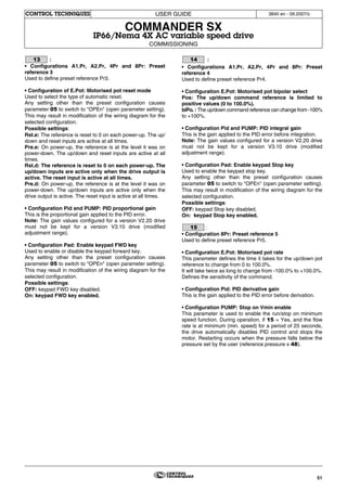


This document provides a user guide for an IP66/Nema 4X rated variable speed drive for controlling AC motors. It discusses safety information and warnings, describes the drive's environmental and electrical characteristics, and lists its optional components. The guide contains information to help ensure the drive is properly installed and commissioned according to regulations.


![Ct2000 pro plus_manual_english[1]](https://cdn.slidesharecdn.com/ss_thumbnails/ct2000proplusmanualenglish1-140613213527-phpapp02-thumbnail.jpg?width=640&height=640&fit=bounds)


![Ct2000 es manual_english_version_1[1].0](https://cdn.slidesharecdn.com/ss_thumbnails/ct2000esmanualenglishversion11-140613213448-phpapp01-thumbnail.jpg?width=640&height=640&fit=bounds)


