SlideShare a Scribd company logo
1 of 16
Download to read offline
Product Manual 03026
(Revision R, 5/2010)
Original Instructions
Permanent Magnet Type Synchronizing
Motor for UG, PSG, and SG Governors
Operation Manual
General
Precautions
Read this entire manual and all other publications pertaining to the work to be
performed before installing, operating, or servicing this equipment.
Practice all plant and safety instructions and precautions.
Failure to follow instructions can cause personal injury and/or property damage.
Revisions
This publication may have been revised or updated since this copy was produced.
To verify that you have the latest revision, check manual 26311 , Revision Status &
Distribution Restrictions of Woodward Technical Publications, on the publications
page of the Woodward website:
www.woodward.com/publications
The latest version of most publications is available on the publications page. If
your publication is not there, please contact your customer service representative
to get the latest copy.
Proper Use
Any unauthorized modifications to or use of this equipment outside its specified
mechanical, electrical, or other operating limits may cause personal injury and/or
property damage, including damage to the equipment. Any such unauthorized
modifications: (i) constitute "misuse" and/or "negligence" within the meaning of
the product warranty thereby excluding warranty coverage for any resulting
damage, and (ii) invalidate product certifications or listings.
Translated
Publications
If the cover of this publication states "Translation of the Original Instructions"
please note:
The original source of this publication may have been updated since this
translation was made. Be sure to check manual 26311 , Revision Status &
Distribution Restrictions of Woodward Technical Publications, to verify whether
this translation is up to date. Out-of-date translations are marked with . Always
compare with the original for technical specifications and for proper and safe
installation and operation procedures.
Revisions—Changes in this publication since the last revision are indicated by a black line
alongside the text.
Woodward reserves the right to update any portion of this publication at any time. Information provided by Woodward is
believed to be correct and reliable. However, no responsibility is assumed by Woodward unless otherwise expressly
undertaken.
Manual 03026
Copyright © Woodward 1991–2010
All Rights Reserved
Manual 03026 Permanent Magnet Synchronizing Motor
Woodward 1
Warnings and Notices
Important Definitions
This is the safety alert symbol. It is used to alert you to potential
personal injury hazards. Obey all safety messages that follow this
symbol to avoid possible injury or death.
 DANGER—Indicates a hazardous situation which, if not avoided, will result
in death or serious injury.
 WARNING—Indicates a hazardous situation which, if not avoided, could
result in death or serious injury.
 CAUTION—Indicates a hazardous situation which, if not avoided, could
result in minor or moderate injury.
 NOTICE—Indicates a hazard that could result in property damage only
(including damage to the control).
 IMPORTANT—Designates an operating tip or maintenance suggestion.
Overspeed /
Overtemperature /
Overpressure
The engine, turbine, or other type of prime mover should be
equipped with an overspeed shutdown device to protect against
runaway or damage to the prime mover with possible personal injury,
loss of life, or property damage.
The overspeed shutdown device must be totally independent of the
prime mover control system. An overtemperature or overpressure
shutdown device may also be needed for safety, as appropriate.
Personal Protective
Equipment
The products described in this publication may present risks that
could lead to personal injury, loss of life, or property damage. Always
wear the appropriate personal protective equipment (PPE) for the job
at hand. Equipment that should be considered includes but is not
limited to:
 Eye Protection
 Hearing Protection
 Hard Hat
 Gloves
 Safety Boots
 Respirator
Always read the proper Material Safety Data Sheet (MSDS) for any
working fluid(s) and comply with recommended safety equipment.
Start-up
Be prepared to make an emergency shutdown when starting the
engine, turbine, or other type of prime mover, to protect against
runaway or overspeed with possible personal injury, loss of life, or
property damage.
Automotive
Applications
On- and off-highway Mobile Applications: Unless Woodward's control
functions as the supervisory control, customer should install a
system totally independent of the prime mover control system that
monitors for supervisory control of engine (and takes appropriate
action if supervisory control is lost) to protect against loss of engine
control with possible personal injury, loss of life, or property damage.
Permanent Magnet Synchronizing Motor Manual 03026
2 Woodward
Battery Charging
Device
To prevent damage to a control system that uses an alternator or
battery-charging device, make sure the charging device is turned off
before disconnecting the battery from the system.
Electrostatic Discharge Awareness
Electrostatic
Precautions
Electronic controls contain static-sensitive parts. Observe the
following precautions to prevent damage to these parts:
 Discharge body static before handling the control (with power to
the control turned off, contact a grounded surface and maintain
contact while handling the control).
 Avoid all plastic, vinyl, and Styrofoam (except antistatic versions)
around printed circuit boards.
 Do not touch the components or conductors on a printed circuit
board with your hands or with conductive devices.
To prevent damage to electronic components caused by improper
handling, read and observe the precautions in Woodward manual
82715, Guide for Handling and Protection of Electronic Controls,
Printed Circuit Boards, and Modules.
Follow these precautions when working with or near the control.
1. Avoid the build-up of static electricity on your body by not wearing clothing
made of synthetic materials. Wear cotton or cotton-blend materials as much
as possible because these do not store static electric charges as much as
synthetics.
2. Do not remove the printed circuit board (PCB) from the control cabinet
unless absolutely necessary. If you must remove the PCB from the control
cabinet, follow these precautions:
 Do not touch any part of the PCB except the edges.
 Do not touch the electrical conductors, the connectors, or the
components with conductive devices or with your hands.
 When replacing a PCB, keep the new PCB in the plastic antistatic
protective bag it comes in until you are ready to install it. Immediately
after removing the old PCB from the control cabinet, place it in the
antistatic protective bag.
Manual 03026 Permanent Magnet Synchronizing Motor
Woodward 3
Permanent Magnet Synchronizing
Motor for UG, PSG, and SG Governors
Description
The permanent-magnet synchronizing motor is used to provide remote speed
adjustment for an SG, PSG, or UG governor. The motor allows a switchboard
operator to match the frequency of an alternator to that of other alternators or to
change load distribution with other units when operating in the droop mode.
The synchronizing motors run only on nominal 24 Vdc power, but models are
available with self-contained rectifiers which allow use of 110 Vac and 220 Vac
supply. A potentiometer is included in most models. This allows the installer to
match the motor with the type of supply available, and to set the motor speed
within an adjustable range.
Four different PM motors have been used to adjust the speed setting of the
governor. The S40, MM40, and MM4A have been used in the past. The current
model is the SMM40. The SMM40 is directly interchangeable with any former
speed-setting motor.
The SMM40 permanent-magnet motor operates on a nominal 24-Vdc supply.
Rectifiers are included in models built to operate with ac supply. In addition a
potentiometer is included with the unit which adjusts dc voltages to an acceptable
level. An adjustable speed is achieved when a PM or APM motor control is
added to the system.
SMM40 Speed
POWER RATED SPEED (RPM) ADJUSTABLE RANGE (RPM)*
24 Vdc
1
2
4
8
0.5 to 1.2
1.2 to 2.5
2.5 to 5
5 to 10
110 Vac/dc
0.5
3
6
0.5 to 1
1 to 4
4 to 9
220 Vac/dc
0.5
3
6
0.5 to 1
1 to 4
4 to 9
* An adjustable range is available when an APM or PM motor control is used. The
adjustment range is only for reference. Exact range depends on the controller used.
Product Specifications
82044 APM Motor Control
82499 Adjustable Voltage Converter for 24 Vdc PM Motor Control
Permanent Magnet Synchronizing Motor Manual 03026
4 Woodward
Adjustment
A friction-type slip clutch between the motor shaft and the governor allows speed
adjustment by the regular manual speed-setting method or by the electrically-
driven PM motor. If this coupling has too little friction the motor drive will slip. With
too great friction the manual speed adjustment will be too hard to turn or set.
The slip clutch also prevents damage to the governor or the speed adjusting
motor when a maximum or minimum stop is attained. (The motor can continue to
run for a short period after a physical stop has been reached.)
The clutch should be adjusted for about 0.5 Nm (4.5 lb-in) of friction. Individual
governor manuals contain instructions on the maintenance and setting of the
friction clutch.
Adjustment Procedure
(There are no adjustments on the MM4A.)
1. Unscrew the four round head screws (828, 515, 605) that hold the cover
plate (825, 519, 602) on the potentiometer portion of the unit.
2. Loosen the lock nut (866, 511, 603) on the potentiometer, turning it
counterclockwise. Turn the potentiometer adjusting shaft (865, 608, 530)
clockwise (toward F on the Bakelite board (834, 510, 601) to increase motor
speed, or counterclockwise (toward S) to decrease motor speed.
When the slot in the shaft points toward the white spot on the Bakelite board
the potentiometer adjustment will be at about the rated speed.
3. After the adjustment has been satisfactorily completed, lock the nut on the
shaft and replace the cover and four round-head screws removed in step 1
of this procedure. (Do not operate the engine for any extended period of
time with the potentiometer and wiring exposed.)
Power Connection
If ac power is used for speed adjustment connect one line from the ac source to
terminal "C" on the receptacle (831, 522, 609). The rectifiers (843, 518, 606) may
burn out if the unit is incorrectly wired. (Review the wiring diagram on the next page
and check against the wiring before applying power to the motor for the first time.)
Terminals "A" and "B" are connected to the respective output poles of the speed-
control switch.
Bearing Lubrication
Ball bearings are permanently packed with a high-quality grease. Repacking or
periodic oiling is not required.
Manual 03026 Permanent Magnet Synchronizing Motor
Woodward 5
Gear Lubrication
The speed reduction gear housing (846, 528, 640, 733) is filled with enough
lubricant to last about two years. Clean out the old grease every two years or as
required and refill with Alvania No. 2 grease or its equivalent.
Wiring Diagrams
Power Connection Diagram
Permanent Magnet Synchronizing Motor Manual 03026
6 Woodward
Troubleshooting
The speed setting motor is extremely long lived and reliable. Most problems
perceived as caused by the motor are in reality caused by either the power
supply to the motor or the friction clutch and speed-setting linkage in the
governor.
Do not disassemble the motor until after all other causes have been thoroughly
investigated. Make sure that the correct power is being delivered to the motor.
Check the connection between the motor and the power source.
Excess load or low supply voltage will slow the speed of the motor. Motor load
can be caused in the governor as well as in the sealed gears on the motor.
Always check for load in the governor by trying to turn the manual speed setting
knob before assuming that excess load is in the motor and attached gears.
Motor heat can be caused by low voltage, excess load, or internal wiring. Always
check causes outside of the motor before determining that the motor is at fault.
Applied voltage can cause motor overspeed. Overspeed conditions are seldom
caused by the motor itself.
Irregular motor speed can be caused by a slipping clutch, problems in the voltage
supply to the motor, of by the motor itself.
Trouble Cause Correction
Motor will not
operate
No applied voltage Power source or motor speed
controller incorrect.
Adjust or exchange power source or
controller.
Fuses are blown. Replace fuse, investigate cause.
Wiring has intermittent open
condition.
Correct wiring.
Applied voltage time is too short. Minimum signal time of 0.2 seconds
for motor response.
Current off Brush spring or wire disconnection. Replace spring or correct wire.
Brush incorrectly installed. Correctly install brush.
Overload,
Overcurrent
Speed-setting gear in governor is
locked up.
Inspect and correct governor.
Excessive wear in speed-setting
bearings.
Replace bearings.
Motor reduction gears. Adjust or replace reduction gears.
Low rpm (motor
speed)
Low Voltage Power source to motor-speed
controller incorrect.
Adjust or exchange power source or
speed controller.
Low Voltage
Control
Voltage incorrect. Correct supply voltage.
Low Motor Torque Brush spring disconnecting or
shorting.
Replace brush and spring.
Insulation incorrect. Clean around brush holder or
replace motor windings.
Overload Motor shaft has overloaded. Inspect governor connection and
speed setting mechanism.
Reduction gear box troubles. Inspect reduction gear box. Replace
grease or parts as necessary.
Bearing wear, lubrication, or
adjustment.
Replace bearings, lubricate, and
adjust as necessary.
Manual 03026 Permanent Magnet Synchronizing Motor
Woodward 7
Trouble Cause Correction
Low rpm Low Voltage Power source or motor speed
controller incorrect.
Adjust or exchange power source.
Voltage incorrect. Check rated voltage, adjust or
exchange power source.
Low motor torque Motor fault. Repair motor or exchange motor.
Insulation incorrect. Clean around brush holder and
brush spring.
Overload Motor shaft has overload. Inspect governor.
Reduction gear box problem. Inspect and repair reduction gear
box. Change lubrication in gear box.
Bearings worn. Replace bearings.
High rpm High voltage Power source or motor speed
controller incorrect.
Adjust or replace power source or
motor speed controller.
Voltage incorrect Check rated voltage. Provide correct voltage to the motor.
Unstable motor
speed
Current is changing Load is changing. Inspect governor, inspect gear box.
Speed controller is not functioning
correctly.
Inspect and repair or replace
controller.
Bearing trouble. Replace or adjust bearings.
Brush spring disconnecting or
shorting.
Replace spring, inspect installation
of brush and spring.
Dirt between brush and commutator. Inspect brush, clean commutator.
Motor is over-
heating
Overcurrent Overload. Repair governor, gear box, or
bearings.
Bearing problem. Replace bearing.
Excessive bearing thrust. Adjust bearing thrust.
Failed brush spring insulation, short. Replace brush spring, check
installation of spring and brush.
Brush holder shorting. Clean around brush holder.
Motor is
overheating
High ambient temperature condition. Improve ventilation, reduce ambient
temperature.
Motor is dirty. Clean motor to improve heat-
exchange capabilities.
Excessive
brush wear
Commutation
incorrect
Overload. Repair governor, gear box, or
bearing.
Abrasive gas in atmosphere. Ventilate with clean air.
Damaged commutator. Polish commutator, replace
armature assembly.
Brush spring tension incorrect or
brush spring is shorting.
Replace the spring, check the brush
installation.
Excessive vibration. Improve mounting or reduce
governor vibration.
Brush material
incorrect
Brush does not match motor
characteristics or installation
conditions.
Change brush composition or
change operating conditions.
Motor operation
is noisy
Excessive vibration Incorrect motor installation. Correct installation.
Motor drive alignment incorrect. Correct alignment.
Dirt or debris in the gap between the
commutator and the brush.
Clean or repair motor.
Motor operation
is noisy cont.
Bearings causing
vibration
Lubrication error. Replace bearing and correct
lubrication.
Damaged bearing surface. Replace bearing and correct
lubrication and adjustment.
Bearing seizure. Replace bearing and correct
lubrication and adjustment.
Commutator
damaged, causing
damage to the
brush
Damaged or worn commutator. Repair commutator or replace
armature and winding assembly.
Abrasive atmosphere. Improve ventilation or change brush
components to match demands of
the atmosphere.
Permanent Magnet Synchronizing Motor Manual 03026
8 Woodward
Replacement Parts
The following pages list replacement parts for the four speed-setting motors
included in this manual. The user must be careful that the illustration and parts
list correctly matches the motor being serviced. A number of parts are identified
in the drawings for information only. These parts are available only through the
purchase of larger assemblies, usually the complete motor assembly.
When ordering replacement parts, include the following information:
1. Serial number and part number shown on the mane plate.
2. Manual number (this is Manual 03026).
3. Part number from parts list and description or part name.
Do not replace the motor until failure of the remote speed-setting
adjustment is clearly identified as failure of the motor. Check wiring
to the motor and power to the motor before assuming that the motor
has failed. If the electrical supply to the motor is determined to be
correct, then carefully check the slip-clutch setting to be sure that it
has not changed. Check the manual speed-setting gear train to be
sure it is not presenting too great a load for the motor to turn.
Manual 03026 Permanent Magnet Synchronizing Motor
Woodward 9
Model S40
Specify Model S40 when ordering parts from this page. Note that the part
numbers are for identification only and are not Woodward part numbers.
Ref. No. Part Name............. Quantity
03026-501 Motor Brush ........................2
03026-502 Brush Spring.......................2
03026-503 Ball Bearing ........................1
03026-504 Ball Bearing ........................1
03026-505 End Housing .......................1
03026-506 Armature.............................1
03026-507 *Ferrite Magnet...................1
03026-508 Potentiometer .....................1
03026-509 *Frame................................1
03026-510 Bakelite Board ....................1
03026-511 Nut......................................1
03026-512 Cross Bar............................1
03026-513 Spring Washer....................4
03026-514 Screw..................................4
03026-515 Screw..................................1
03026-516 Stop Ring............................1
03026-517 Vinyl Washer ......................1
Ref. No. Part Name .............Quantity
03026-518 Rectifier .............................. 2
03026-519 Enclosing Cover ................. 1
03026-520 Plug.................................... 1
03026-521 Cable Clamp....................... 1
03026-522 Receptacle ......................... 1
03026-523 Condenser.......................... 1
03026-524 Worm Gear Shaft ............... 1
03026-525 Bakelite Gear...................... 1
03026-526 Bronze Gear....................... 1
03026-527 Output Shaft ....................... 1
03026-528 *Reduction Gear Box.......... 1
03026-529 Sleeve ................................ 2
03026-530 *Adjusting Shaft.................. 1
03026-531 Screw ................................. 3
03026-532 Nut...................................... 3
03026-533 Washer............................... 3
* Parts available only in connection with larger assembly.
Permanent Magnet Synchronizing Motor Manual 03026
10 Woodward
Model MM40
(Speed Setting serial numbers 21105 and after are model MM40. Note that the
part numbers are for identification only and are not Woodward part numbers.
Ref. No. Part Name .............Quantity
03026-601 Bakelite Board.................... 1
03026-602 Pot Cover ........................... 1
03026-603 Potentiometer..................... 1
03026-604 Rd Hd Screw.................... 12
03026-605 Spring Washer ................. 14
03026-606 Rectifier.............................. 2
03026-607 Flat Washer........................ 6
03026-608 Gasket................................ 1
03026-609 Receptacle ......................... 1
03026-610 Plug.................................... 1
03026-611 Cable Clamp ...................... 1
03026-612 Condenser.......................... 1
03026-613 Ball Bearing........................ 1
03026-614 Rd Hd Screw...................... 2
03026-615 Alum. Washer..................... 1
03026-616 Retaining Ring.................... 1
03026-617 Bearing Retainer ................ 1
03026-618 Brush Holder Board............ 1
03026-619 End Cover .......................... 1
03026-620 Motor Brush........................ 2
03036-620A Brush Holder Assy.............. 1
03026-621 Brush Spring ...................... 2
03026-622 *Bracket.............................. 1
03026-623 Armature Assy.................... 1
03026-624 *Ferrite Magnet .................. 1
03026-625 *Stator Assy ....................... 1
Ref. No. Part Name ............. Quantity
03026-626 *Body ..................................1
03026-627 Ball Bearing ........................1
03026-628 Alum Washer ......................1
03026-629 Bearing Cap........................1
03026-630 Retaining Ring ....................1
03026-631 Bearing Retaining Ring.......1
03026-632 *Pot. Box.............................1
03026-633 Gasket ................................1
03026-634 Plate....................................1
03026-635 Name Plate .........................1
03026-636 Grommet.............................1
03026-637 Worm Shaft.........................1
03026-638 Helical Gear ........................1
03026-639 Rd Hd Screw.........................
03026-640 *Gear Housing ....................1
03026-641 Oil Seal ...............................1
03026-642 Output Shaft........................1
03026-643 Helical Gear ........................1
03026-644 Fiber Washer ......................3
03026-645 Lock Nut..............................3
03026-646 Adjusting Plug.....................3
03026-647 Ball......................................3
03026-648 Ball Seat .............................1
03026-649 Damping Bushing................1
03026-650 Rd Hd Screw.......................4
NOTE—Units with the Damping Rubber Bushing use 8 parts 604 and 10 parts 607.
* Parts available only in connection with larger assembly.
Manual 03026 Permanent Magnet Synchronizing Motor
Woodward 11
Model MM4A
This model does not include built in rectifiers or a voltage adjustment
potentiometer. Note that the part numbers are for identification only and are not
Woodward part numbers.
Ref. No. Part Name............. Quantity
03026-701 *Front Housing....................1
03026-702 *Body..................................1
03026-703 *Stator Assembly ................1
03026-704 *Ferrite Magnet...................1
03026-705 *Retaining Ring...................1
03026-706 *Rd Hd Screw .....................2
03026-707 *Spring Washer...................2
03026-708 *Flat Washer.......................2
03026-709 Bearing Cap........................1
03026-710 Retaining Ring ....................1
03026-711 Alum Washer ......................1
03026-713 Alum Washer ......................2
03026-714 Bearing Retainer.................1
03026-715 Bearing Retainer.................1
03026-716 Ball Bearing ........................1
03026-717 Ball Bearing ........................1
03026-718 Condenser ..........................1
03026-719 *Insulator ............................1
03026-720 *Motor Cover ......................1
03026-721 *Rd Hd Screw .....................2
03026-722 *Armature ...........................1
03026-723 Brush Holder Assy..............1
03026-724 Motor Brush ........................2
03026-725 Brush Spring.......................2
03026-726 *Rd Hd Screw .....................2
Ref. No. Part Name .............Quantity
03026-727 *Grommet........................... 1
03026-728 Name Plate ........................ 1
03026-729 Brush Holder Board............ 1
03026-730 Worm Shaft ........................ 1
03026-731 Helical Gear........................ 1
03026-732 Rd Hd Screw ...................... 1
03026-733 Gear Housing ..................... 1
03026-734 Oil Seal............................... 1
03026-735 Output Shaft ....................... 1
03026-736 Helical Gear........................ 1
03026-737 Fiber Washer...................... 3
03026-738 Lock Nut ............................. 3
03026-739 Adjusting Plug .................... 3
03026-740 Ball ..................................... 3
03026-741 Ball Seat............................. 3
03026-742 *Cover ................................ 1
03026-752 *Name Plate ....................... 1
03026-753 *Plate.................................. 1
03026-754 Rd Hd Screw ...................... 4
03026-755 Gasket................................ 1
03026-756 Rd Hd Screw ...................... 4
03026-757 Plug.................................... 1
03026-758 Cable Clamp....................... 1
03026-759 Screw ................................. 4
03026-760 *Box.................................... 1
* Parts available only in connection with larger assembly.
Permanent Magnet Synchronizing Motor Manual 03026
12 Woodward
Model SMM40
This motor will replace any other speed-setting motor. Most parts, however, are
not interchangeable. Note that the part numbers are for identification only and
are not Woodward part numbers. Housing is IP44.
 
Manual 03026 Permanent Magnet Synchronizing Motor
Woodward 13
Ref. No. Part Name............. Quantity
03026-801 *Front Housing....................1
03026-802 *Body..................................1
03026-803 *Stator Assy........................1
03026-804 PH Hd Screw ......................2
03026-805 Spring Washer....................2
03026-806 Retaining Ring ....................1
03026-807 Retaining Ring ....................1
03026-808 Cap.....................................1
03026-809 Alum Washer ......................2
03026-810 Alum Washer ......................2
03026-811 Bearing Retainer.................1
03026-812 Bearing Retainer.................1
03026-813 Ball Bearing ........................1
03026-814 Ball Bearing ........................1
03026-815 Holder Cap .........................2
03026-816 Brush Assy .........................2
03026-817 *Brush Holder .....................2
03026-818 *Grommet ...........................1
03026-819 Lead Wire ........................AR
03026-820 Armature.............................1
03026-821 PH Hd Screw ............ max 10
03026-822 Flat Washer ........................2
03026-823 Set Screw ...........................1
03026-824 *Potentiometer Box.............1
03026-825 Potentiometer Cover...........1
03026-826 Gasket ................................1
03026-827 Gasket ................................1
03026-828 Removed
03026-829 Removed
03026-830 PH Hd Screw ...............3 or 4
03026-831 Receptacle..........................1
03026-832 Plug & Cable Clamp ...........1
03026-833 Removed
03026-834 Bakelite Board ....................1
03026-835 Potentiometer .....................1
03026-836 Damping Bushing ...............8
03026-837 Slotted Hd Screw................4
03026-838 Insulated Terminal ..............2
03026-839 Spring Washer....................1
03026-840 Pan Hd Screw.....................5
03026-841 Spring Lock Washer ...........5
03026-842 Terminal..............................5
Ref. No. Part Name .............Quantity
03026-843 Diode Rectifier.................... 2
03026-844 Plate................................... 1
03026-845 *Grommet........................... 1
03026-846 *Gear Housing.................... 1
03026-847 Bushing .............................. 4
03026-848 Motor Shaft......................... 1
03026-849 Ball Seat............................. 3
03026-850 Hex Nut .............................. 3
03026-851 Shim................................... 3
03026-852 Fiber Washer...................... 3
03026-853 Worm Gear Shaft ............... 1
03026-854 Helical Gear........................ 1
03026-855 Helical Gear........................ 1
03026-856 Oil Seal............................... 2
03026-857 Screw ................................. 1
03026-858 Screw ................................. 2
03026-859 Screw ................................. 2
03026-860 Washer............................... 3
03026-861 Spacer................................ 1
03026-862 Spacer................................ 1
03026-863 Retainer.............................. 1
03026-864 Ball ..................................... 3
03026-865 Nameplate.......................... 1
03026-866 Terminal Block.................... 1
03026-867 Bakelite Board.................... 1
03026-868 PH Hd Screw...................... 4
03026-869 Hex Nut .............................. 4
03026-870 Sleeve ................................ 1
03026-871 Removed
03026-872 PH Hd Screw...................... 1
03026-873 Gland Lock Nut................... 1
03026-874 Gland Packing.................... 1
03026-875 Gland Lock Union............... 1
03026-876 Gland Nut ........................... 1
03026-877 Gland Lock Joint................. 1
03026-878 Motor Label ........................ 1
03026-879 Cable Clamp Bushing......... 1
03026-880 Board.................................. 1
03026-881 Insulated Terminal.............. 1
03026-882 Bearing Cap ....................... 1
03026-883 O-ring ................................. 1
03026-884 Gasket................................ 1
* Parts available only in connection with larger assembly.
We appreciate your comments about the content of our publications.
Send comments to: icinfo@woodward.com
Please reference publication 03026R.
PO Box 1519, Fort Collins CO 80522-1519, USA
1000 East Drake Road, Fort Collins CO 80525, USA
Phone +1 (970) 482-5811  Fax +1 (970) 498-3058
Email and Website—www.woodward.com
Woodward has company-owned plants, subsidiaries, and branches,
as well as authorized distributors and other authorized service and sales facilities throughout the world.
Complete address / phone / fax / email information for all locations is available on our website.

More Related Content

What's hot

Siemens s7 300 module data manual
Siemens s7 300 module data manualSiemens s7 300 module data manual
Siemens s7 300 module data manualsteven qi
 
322 electrical system caterpillar (1)
322 electrical system caterpillar (1)322 electrical system caterpillar (1)
322 electrical system caterpillar (1)Fabio Junior
 
BS ISO 10816-3-2009+A1-2017.pdf
BS ISO 10816-3-2009+A1-2017.pdfBS ISO 10816-3-2009+A1-2017.pdf
BS ISO 10816-3-2009+A1-2017.pdffranciscafica1
 
PLC: Manual de usuario de PLC Micrologix1500.pdf
PLC: Manual de usuario de PLC Micrologix1500.pdfPLC: Manual de usuario de PLC Micrologix1500.pdf
PLC: Manual de usuario de PLC Micrologix1500.pdfSantiagoPabloAlberto1
 
Siemens micro master 440 quick-start-guide
Siemens micro master 440 quick-start-guideSiemens micro master 440 quick-start-guide
Siemens micro master 440 quick-start-guideDien Ha The
 
Workshop manual 320_420_620_634
Workshop manual 320_420_620_634Workshop manual 320_420_620_634
Workshop manual 320_420_620_634Lincon Fernandes
 
InduSoft Web Studio and MQTT for Internet of Things Applications
InduSoft Web Studio and MQTT for Internet of Things ApplicationsInduSoft Web Studio and MQTT for Internet of Things Applications
InduSoft Web Studio and MQTT for Internet of Things ApplicationsAVEVA
 
SIMATIC S7-1200: Easily adapted to suit your needs easy book en-us
SIMATIC S7-1200: Easily adapted to suit your needs easy book en-usSIMATIC S7-1200: Easily adapted to suit your needs easy book en-us
SIMATIC S7-1200: Easily adapted to suit your needs easy book en-usRushabh Patel
 
AUTOMATAS PROGRAMABLES SIEMENS GRAFCET Y GUIA GEMMA CON TIA PORTAL.pdf
AUTOMATAS PROGRAMABLES SIEMENS GRAFCET Y GUIA GEMMA CON TIA PORTAL.pdfAUTOMATAS PROGRAMABLES SIEMENS GRAFCET Y GUIA GEMMA CON TIA PORTAL.pdf
AUTOMATAS PROGRAMABLES SIEMENS GRAFCET Y GUIA GEMMA CON TIA PORTAL.pdfMarioHaguila
 
7 cuidados especiales para las transmisiones de doble embrague
7 cuidados especiales para las transmisiones de doble embrague7 cuidados especiales para las transmisiones de doble embrague
7 cuidados especiales para las transmisiones de doble embraguesoloautos
 
Fundamentos del sistema rslogix5000 lvl1 control logix
Fundamentos del sistema rslogix5000 lvl1  control logixFundamentos del sistema rslogix5000 lvl1  control logix
Fundamentos del sistema rslogix5000 lvl1 control logixJuanito Dominguez
 
Weg guia-de-selecao-de-partida-direta-918-catalogo-portugues-br
Weg guia-de-selecao-de-partida-direta-918-catalogo-portugues-brWeg guia-de-selecao-de-partida-direta-918-catalogo-portugues-br
Weg guia-de-selecao-de-partida-direta-918-catalogo-portugues-brdeltatecnologia
 

What's hot (20)

Siemens s7 300 module data manual
Siemens s7 300 module data manualSiemens s7 300 module data manual
Siemens s7 300 module data manual
 
322 electrical system caterpillar (1)
322 electrical system caterpillar (1)322 electrical system caterpillar (1)
322 electrical system caterpillar (1)
 
BS ISO 10816-3-2009+A1-2017.pdf
BS ISO 10816-3-2009+A1-2017.pdfBS ISO 10816-3-2009+A1-2017.pdf
BS ISO 10816-3-2009+A1-2017.pdf
 
PLC: Manual de usuario de PLC Micrologix1500.pdf
PLC: Manual de usuario de PLC Micrologix1500.pdfPLC: Manual de usuario de PLC Micrologix1500.pdf
PLC: Manual de usuario de PLC Micrologix1500.pdf
 
Siemens micro master 440 quick-start-guide
Siemens micro master 440 quick-start-guideSiemens micro master 440 quick-start-guide
Siemens micro master 440 quick-start-guide
 
Workshop manual 320_420_620_634
Workshop manual 320_420_620_634Workshop manual 320_420_620_634
Workshop manual 320_420_620_634
 
InduSoft Web Studio and MQTT for Internet of Things Applications
InduSoft Web Studio and MQTT for Internet of Things ApplicationsInduSoft Web Studio and MQTT for Internet of Things Applications
InduSoft Web Studio and MQTT for Internet of Things Applications
 
SIMATIC S7-1200: Easily adapted to suit your needs easy book en-us
SIMATIC S7-1200: Easily adapted to suit your needs easy book en-usSIMATIC S7-1200: Easily adapted to suit your needs easy book en-us
SIMATIC S7-1200: Easily adapted to suit your needs easy book en-us
 
Catalog Sew-Eurodrive
Catalog Sew-EurodriveCatalog Sew-Eurodrive
Catalog Sew-Eurodrive
 
Manual logo ago_13
Manual logo ago_13 Manual logo ago_13
Manual logo ago_13
 
Seguridad eléctrica Uruguay
Seguridad eléctrica UruguaySeguridad eléctrica Uruguay
Seguridad eléctrica Uruguay
 
AUTOMATAS PROGRAMABLES SIEMENS GRAFCET Y GUIA GEMMA CON TIA PORTAL.pdf
AUTOMATAS PROGRAMABLES SIEMENS GRAFCET Y GUIA GEMMA CON TIA PORTAL.pdfAUTOMATAS PROGRAMABLES SIEMENS GRAFCET Y GUIA GEMMA CON TIA PORTAL.pdf
AUTOMATAS PROGRAMABLES SIEMENS GRAFCET Y GUIA GEMMA CON TIA PORTAL.pdf
 
7 cuidados especiales para las transmisiones de doble embrague
7 cuidados especiales para las transmisiones de doble embrague7 cuidados especiales para las transmisiones de doble embrague
7 cuidados especiales para las transmisiones de doble embrague
 
Qac22 fiche produit_fr
Qac22 fiche produit_frQac22 fiche produit_fr
Qac22 fiche produit_fr
 
Guia intouch
Guia intouchGuia intouch
Guia intouch
 
Fundamentos del sistema rslogix5000 lvl1 control logix
Fundamentos del sistema rslogix5000 lvl1  control logixFundamentos del sistema rslogix5000 lvl1  control logix
Fundamentos del sistema rslogix5000 lvl1 control logix
 
HMI Design
HMI DesignHMI Design
HMI Design
 
Weg guia-de-selecao-de-partida-direta-918-catalogo-portugues-br
Weg guia-de-selecao-de-partida-direta-918-catalogo-portugues-brWeg guia-de-selecao-de-partida-direta-918-catalogo-portugues-br
Weg guia-de-selecao-de-partida-direta-918-catalogo-portugues-br
 
Grafcet
GrafcetGrafcet
Grafcet
 
Data Error Grove-2da-parte
Data Error Grove-2da-parteData Error Grove-2da-parte
Data Error Grove-2da-parte
 

Similar to 367465305 woodward-732

Commander sx user guide
Commander sx user guideCommander sx user guide
Commander sx user guideToàn Huỳnh
 
Sv i p5a-manual_(english)
Sv i p5a-manual_(english)Sv i p5a-manual_(english)
Sv i p5a-manual_(english)Toàn Huỳnh
 
J1000 quickstartguide
J1000 quickstartguideJ1000 quickstartguide
J1000 quickstartguideToàn Huỳnh
 
MSLC-2_PRODUCT-MANUAL_EN_2017.pdf
MSLC-2_PRODUCT-MANUAL_EN_2017.pdfMSLC-2_PRODUCT-MANUAL_EN_2017.pdf
MSLC-2_PRODUCT-MANUAL_EN_2017.pdfssuserad794a
 
B 65285 en-04
B 65285 en-04B 65285 en-04
B 65285 en-04mt7038
 
Commander se users guide
Commander se users guideCommander se users guide
Commander se users guideToàn Huỳnh
 
Fanuc 0i maintenance manual CNC milling machine
Fanuc 0i maintenance manual CNC milling machineFanuc 0i maintenance manual CNC milling machine
Fanuc 0i maintenance manual CNC milling machineCNCDATAN
 
430 opi 24479264_en_1006
430 opi 24479264_en_1006430 opi 24479264_en_1006
430 opi 24479264_en_1006Toàn Huỳnh
 
Micromaster 420 operating instructions
Micromaster 420 operating instructionsMicromaster 420 operating instructions
Micromaster 420 operating instructionsDagobert Aldus
 
420 opi 24523400_en_1006
420 opi 24523400_en_1006420 opi 24523400_en_1006
420 opi 24523400_en_1006Toàn Huỳnh
 
John Deere 850jr Crawler Dozer Mct Operation And Test Technical Manual.pdf
John Deere 850jr Crawler Dozer Mct Operation And Test Technical Manual.pdfJohn Deere 850jr Crawler Dozer Mct Operation And Test Technical Manual.pdf
John Deere 850jr Crawler Dozer Mct Operation And Test Technical Manual.pdfExcavator
 
John Deere 850jr Crawler Dozer Mct Operation And Test Technical Manual.pdf
John Deere 850jr Crawler Dozer Mct Operation And Test Technical Manual.pdfJohn Deere 850jr Crawler Dozer Mct Operation And Test Technical Manual.pdf
John Deere 850jr Crawler Dozer Mct Operation And Test Technical Manual.pdfReparacionPcLaptopsDesktop
 
Datasheet r7 m a10030_s1
Datasheet  r7 m a10030_s1Datasheet  r7 m a10030_s1
Datasheet r7 m a10030_s1Đức Hữu
 
John Deere 850jr Crawler Dozer Mct (tm10779) Service Repair Manual.pdf
John Deere 850jr Crawler Dozer Mct (tm10779) Service Repair Manual.pdfJohn Deere 850jr Crawler Dozer Mct (tm10779) Service Repair Manual.pdf
John Deere 850jr Crawler Dozer Mct (tm10779) Service Repair Manual.pdfReparacionPcLaptopsDesktop
 

Similar to 367465305 woodward-732 (20)

Commander sx user guide
Commander sx user guideCommander sx user guide
Commander sx user guide
 
Sv i p5a-manual_(english)
Sv i p5a-manual_(english)Sv i p5a-manual_(english)
Sv i p5a-manual_(english)
 
J1000 quickstartguide
J1000 quickstartguideJ1000 quickstartguide
J1000 quickstartguide
 
Vfd s manual-en
Vfd s manual-enVfd s manual-en
Vfd s manual-en
 
Quick start l1000 a
Quick start l1000 aQuick start l1000 a
Quick start l1000 a
 
MSLC-2_PRODUCT-MANUAL_EN_2017.pdf
MSLC-2_PRODUCT-MANUAL_EN_2017.pdfMSLC-2_PRODUCT-MANUAL_EN_2017.pdf
MSLC-2_PRODUCT-MANUAL_EN_2017.pdf
 
B 65285 en-04
B 65285 en-04B 65285 en-04
B 65285 en-04
 
Atv12
Atv12Atv12
Atv12
 
F7 user manual
F7 user manualF7 user manual
F7 user manual
 
Commander se users guide
Commander se users guideCommander se users guide
Commander se users guide
 
Fanuc 0i maintenance manual CNC milling machine
Fanuc 0i maintenance manual CNC milling machineFanuc 0i maintenance manual CNC milling machine
Fanuc 0i maintenance manual CNC milling machine
 
430 opi 24479264_en_1006
430 opi 24479264_en_1006430 opi 24479264_en_1006
430 opi 24479264_en_1006
 
AC Drive/Inverter Fuji Frenic Mini
AC Drive/Inverter Fuji Frenic MiniAC Drive/Inverter Fuji Frenic Mini
AC Drive/Inverter Fuji Frenic Mini
 
Micromaster 420 operating instructions
Micromaster 420 operating instructionsMicromaster 420 operating instructions
Micromaster 420 operating instructions
 
420 opi 24523400_en_1006
420 opi 24523400_en_1006420 opi 24523400_en_1006
420 opi 24523400_en_1006
 
John Deere 850jr Crawler Dozer Mct Operation And Test Technical Manual.pdf
John Deere 850jr Crawler Dozer Mct Operation And Test Technical Manual.pdfJohn Deere 850jr Crawler Dozer Mct Operation And Test Technical Manual.pdf
John Deere 850jr Crawler Dozer Mct Operation And Test Technical Manual.pdf
 
John Deere 850jr Crawler Dozer Mct Operation And Test Technical Manual.pdf
John Deere 850jr Crawler Dozer Mct Operation And Test Technical Manual.pdfJohn Deere 850jr Crawler Dozer Mct Operation And Test Technical Manual.pdf
John Deere 850jr Crawler Dozer Mct Operation And Test Technical Manual.pdf
 
Datasheet r7 m a10030_s1
Datasheet  r7 m a10030_s1Datasheet  r7 m a10030_s1
Datasheet r7 m a10030_s1
 
Manual BPD - Series Solar Pumping Inverter
Manual BPD - Series Solar Pumping InverterManual BPD - Series Solar Pumping Inverter
Manual BPD - Series Solar Pumping Inverter
 
John Deere 850jr Crawler Dozer Mct (tm10779) Service Repair Manual.pdf
John Deere 850jr Crawler Dozer Mct (tm10779) Service Repair Manual.pdfJohn Deere 850jr Crawler Dozer Mct (tm10779) Service Repair Manual.pdf
John Deere 850jr Crawler Dozer Mct (tm10779) Service Repair Manual.pdf
 

Recently uploaded

Bhubaneswar🌹Vip Call Girls Odisha❤Heer 9777949614 💟 Full Trusted CALL GIRLS I...
Bhubaneswar🌹Vip Call Girls Odisha❤Heer 9777949614 💟 Full Trusted CALL GIRLS I...Bhubaneswar🌹Vip Call Girls Odisha❤Heer 9777949614 💟 Full Trusted CALL GIRLS I...
Bhubaneswar🌹Vip Call Girls Odisha❤Heer 9777949614 💟 Full Trusted CALL GIRLS I...jabtakhaidam7
 
Mankhurd Call Girls, 09167354423 Mankhurd Escorts Services,Mankhurd Female Es...
Mankhurd Call Girls, 09167354423 Mankhurd Escorts Services,Mankhurd Female Es...Mankhurd Call Girls, 09167354423 Mankhurd Escorts Services,Mankhurd Female Es...
Mankhurd Call Girls, 09167354423 Mankhurd Escorts Services,Mankhurd Female Es...Priya Reddy
 
Phool Bagan / VIP Call Girls Kolkata | Whatsapp No 8005736733 VIP Escorts Ser...
Phool Bagan / VIP Call Girls Kolkata | Whatsapp No 8005736733 VIP Escorts Ser...Phool Bagan / VIP Call Girls Kolkata | Whatsapp No 8005736733 VIP Escorts Ser...
Phool Bagan / VIP Call Girls Kolkata | Whatsapp No 8005736733 VIP Escorts Ser...HyderabadDolls
 
Jual Obat Aborsi Samarinda ( No.1 ) 088980685493 Obat Penggugur Kandungan Cy...
Jual Obat Aborsi Samarinda (  No.1 ) 088980685493 Obat Penggugur Kandungan Cy...Jual Obat Aborsi Samarinda (  No.1 ) 088980685493 Obat Penggugur Kandungan Cy...
Jual Obat Aborsi Samarinda ( No.1 ) 088980685493 Obat Penggugur Kandungan Cy...Obat Aborsi 088980685493 Jual Obat Aborsi
 
Shimoga Escorts Service Girl ^ 9332606886, WhatsApp Anytime Shimoga
Shimoga Escorts Service Girl ^ 9332606886, WhatsApp Anytime ShimogaShimoga Escorts Service Girl ^ 9332606886, WhatsApp Anytime Shimoga
Shimoga Escorts Service Girl ^ 9332606886, WhatsApp Anytime Shimogameghakumariji156
 
一比一原版(USYD毕业证书)澳洲悉尼大学毕业证如何办理
一比一原版(USYD毕业证书)澳洲悉尼大学毕业证如何办理一比一原版(USYD毕业证书)澳洲悉尼大学毕业证如何办理
一比一原版(USYD毕业证书)澳洲悉尼大学毕业证如何办理uodye
 
一比一原版(CSUEB毕业证书)东湾分校毕业证原件一模一样
一比一原版(CSUEB毕业证书)东湾分校毕业证原件一模一样一比一原版(CSUEB毕业证书)东湾分校毕业证原件一模一样
一比一原版(CSUEB毕业证书)东湾分校毕业证原件一模一样ayoqf
 
Call Girls Service Lucknow {0000000000 } ❤️VVIP BHAWNA Call Girl in Lucknow U.P
Call Girls Service Lucknow {0000000000 } ❤️VVIP BHAWNA Call Girl in Lucknow U.PCall Girls Service Lucknow {0000000000 } ❤️VVIP BHAWNA Call Girl in Lucknow U.P
Call Girls Service Lucknow {0000000000 } ❤️VVIP BHAWNA Call Girl in Lucknow U.Pjabtakhaidam7
 
£ HAMIL 5 BULAN £ CARA MENGGUGURKAN KANDUNGAN USIA 5 BULAN ((087776558899))
£ HAMIL 5 BULAN £ CARA MENGGUGURKAN KANDUNGAN USIA 5 BULAN ((087776558899))£ HAMIL 5 BULAN £ CARA MENGGUGURKAN KANDUNGAN USIA 5 BULAN ((087776558899))
£ HAMIL 5 BULAN £ CARA MENGGUGURKAN KANDUNGAN USIA 5 BULAN ((087776558899))Obat Cytotec
 
Top profile Call Girls In Palghar [ 7014168258 ] Call Me For Genuine Models W...
Top profile Call Girls In Palghar [ 7014168258 ] Call Me For Genuine Models W...Top profile Call Girls In Palghar [ 7014168258 ] Call Me For Genuine Models W...
Top profile Call Girls In Palghar [ 7014168258 ] Call Me For Genuine Models W...gajnagarg
 
Vashi Affordable Call Girls ,07506202331,Vasai Virar Charming Call Girl
Vashi Affordable Call Girls ,07506202331,Vasai Virar Charming Call GirlVashi Affordable Call Girls ,07506202331,Vasai Virar Charming Call Girl
Vashi Affordable Call Girls ,07506202331,Vasai Virar Charming Call GirlPriya Reddy
 
Call Girls in Bhubaneswar Patia Escort Service(🔝))/WhatsApp 97779⇛49614
Call Girls in Bhubaneswar Patia Escort Service(🔝))/WhatsApp 97779⇛49614Call Girls in Bhubaneswar Patia Escort Service(🔝))/WhatsApp 97779⇛49614
Call Girls in Bhubaneswar Patia Escort Service(🔝))/WhatsApp 97779⇛49614jabtakhaidam7
 
如何办理(USYD毕业证书)悉尼大学毕业证成绩单原件一模一样
如何办理(USYD毕业证书)悉尼大学毕业证成绩单原件一模一样如何办理(USYD毕业证书)悉尼大学毕业证成绩单原件一模一样
如何办理(USYD毕业证书)悉尼大学毕业证成绩单原件一模一样wsppdmt
 
Lucknow Call Girls U.P 👉👉 0000000000 Top Class Call Girl Service Available
Lucknow Call Girls U.P 👉👉 0000000000 Top Class Call Girl Service AvailableLucknow Call Girls U.P 👉👉 0000000000 Top Class Call Girl Service Available
Lucknow Call Girls U.P 👉👉 0000000000 Top Class Call Girl Service Availablejabtakhaidam7
 
一比一定(购)坎特伯雷大学毕业证(UC毕业证)成绩单学位证
一比一定(购)坎特伯雷大学毕业证(UC毕业证)成绩单学位证一比一定(购)坎特伯雷大学毕业证(UC毕业证)成绩单学位证
一比一定(购)坎特伯雷大学毕业证(UC毕业证)成绩单学位证wpkuukw
 
Call Girls Amethi 9332606886 HOT & SEXY Models beautiful and charming call g...
Call Girls Amethi  9332606886 HOT & SEXY Models beautiful and charming call g...Call Girls Amethi  9332606886 HOT & SEXY Models beautiful and charming call g...
Call Girls Amethi 9332606886 HOT & SEXY Models beautiful and charming call g...Sareena Khatun
 
Guwahati Escorts Service Girl ^ 9332606886, WhatsApp Anytime Guwahati
Guwahati Escorts Service Girl ^ 9332606886, WhatsApp Anytime GuwahatiGuwahati Escorts Service Girl ^ 9332606886, WhatsApp Anytime Guwahati
Guwahati Escorts Service Girl ^ 9332606886, WhatsApp Anytime Guwahatimeghakumariji156
 

Recently uploaded (20)

Bhubaneswar🌹Vip Call Girls Odisha❤Heer 9777949614 💟 Full Trusted CALL GIRLS I...
Bhubaneswar🌹Vip Call Girls Odisha❤Heer 9777949614 💟 Full Trusted CALL GIRLS I...Bhubaneswar🌹Vip Call Girls Odisha❤Heer 9777949614 💟 Full Trusted CALL GIRLS I...
Bhubaneswar🌹Vip Call Girls Odisha❤Heer 9777949614 💟 Full Trusted CALL GIRLS I...
 
Mankhurd Call Girls, 09167354423 Mankhurd Escorts Services,Mankhurd Female Es...
Mankhurd Call Girls, 09167354423 Mankhurd Escorts Services,Mankhurd Female Es...Mankhurd Call Girls, 09167354423 Mankhurd Escorts Services,Mankhurd Female Es...
Mankhurd Call Girls, 09167354423 Mankhurd Escorts Services,Mankhurd Female Es...
 
Phool Bagan / VIP Call Girls Kolkata | Whatsapp No 8005736733 VIP Escorts Ser...
Phool Bagan / VIP Call Girls Kolkata | Whatsapp No 8005736733 VIP Escorts Ser...Phool Bagan / VIP Call Girls Kolkata | Whatsapp No 8005736733 VIP Escorts Ser...
Phool Bagan / VIP Call Girls Kolkata | Whatsapp No 8005736733 VIP Escorts Ser...
 
Jual Obat Aborsi Samarinda ( No.1 ) 088980685493 Obat Penggugur Kandungan Cy...
Jual Obat Aborsi Samarinda (  No.1 ) 088980685493 Obat Penggugur Kandungan Cy...Jual Obat Aborsi Samarinda (  No.1 ) 088980685493 Obat Penggugur Kandungan Cy...
Jual Obat Aborsi Samarinda ( No.1 ) 088980685493 Obat Penggugur Kandungan Cy...
 
Buy Abortion pills in Riyadh |+966572737505 | Get Cytotec
Buy Abortion pills in Riyadh |+966572737505 | Get CytotecBuy Abortion pills in Riyadh |+966572737505 | Get Cytotec
Buy Abortion pills in Riyadh |+966572737505 | Get Cytotec
 
Abortion pills in Riyadh Saudi Arabia!+966572737505 ) Where to get cytotec
Abortion pills in Riyadh Saudi Arabia!+966572737505 ) Where to get cytotecAbortion pills in Riyadh Saudi Arabia!+966572737505 ) Where to get cytotec
Abortion pills in Riyadh Saudi Arabia!+966572737505 ) Where to get cytotec
 
Shimoga Escorts Service Girl ^ 9332606886, WhatsApp Anytime Shimoga
Shimoga Escorts Service Girl ^ 9332606886, WhatsApp Anytime ShimogaShimoga Escorts Service Girl ^ 9332606886, WhatsApp Anytime Shimoga
Shimoga Escorts Service Girl ^ 9332606886, WhatsApp Anytime Shimoga
 
一比一原版(USYD毕业证书)澳洲悉尼大学毕业证如何办理
一比一原版(USYD毕业证书)澳洲悉尼大学毕业证如何办理一比一原版(USYD毕业证书)澳洲悉尼大学毕业证如何办理
一比一原版(USYD毕业证书)澳洲悉尼大学毕业证如何办理
 
一比一原版(CSUEB毕业证书)东湾分校毕业证原件一模一样
一比一原版(CSUEB毕业证书)东湾分校毕业证原件一模一样一比一原版(CSUEB毕业证书)东湾分校毕业证原件一模一样
一比一原版(CSUEB毕业证书)东湾分校毕业证原件一模一样
 
Call Girls Service Lucknow {0000000000 } ❤️VVIP BHAWNA Call Girl in Lucknow U.P
Call Girls Service Lucknow {0000000000 } ❤️VVIP BHAWNA Call Girl in Lucknow U.PCall Girls Service Lucknow {0000000000 } ❤️VVIP BHAWNA Call Girl in Lucknow U.P
Call Girls Service Lucknow {0000000000 } ❤️VVIP BHAWNA Call Girl in Lucknow U.P
 
£ HAMIL 5 BULAN £ CARA MENGGUGURKAN KANDUNGAN USIA 5 BULAN ((087776558899))
£ HAMIL 5 BULAN £ CARA MENGGUGURKAN KANDUNGAN USIA 5 BULAN ((087776558899))£ HAMIL 5 BULAN £ CARA MENGGUGURKAN KANDUNGAN USIA 5 BULAN ((087776558899))
£ HAMIL 5 BULAN £ CARA MENGGUGURKAN KANDUNGAN USIA 5 BULAN ((087776558899))
 
Top profile Call Girls In Palghar [ 7014168258 ] Call Me For Genuine Models W...
Top profile Call Girls In Palghar [ 7014168258 ] Call Me For Genuine Models W...Top profile Call Girls In Palghar [ 7014168258 ] Call Me For Genuine Models W...
Top profile Call Girls In Palghar [ 7014168258 ] Call Me For Genuine Models W...
 
Vashi Affordable Call Girls ,07506202331,Vasai Virar Charming Call Girl
Vashi Affordable Call Girls ,07506202331,Vasai Virar Charming Call GirlVashi Affordable Call Girls ,07506202331,Vasai Virar Charming Call Girl
Vashi Affordable Call Girls ,07506202331,Vasai Virar Charming Call Girl
 
Call Girls in Bhubaneswar Patia Escort Service(🔝))/WhatsApp 97779⇛49614
Call Girls in Bhubaneswar Patia Escort Service(🔝))/WhatsApp 97779⇛49614Call Girls in Bhubaneswar Patia Escort Service(🔝))/WhatsApp 97779⇛49614
Call Girls in Bhubaneswar Patia Escort Service(🔝))/WhatsApp 97779⇛49614
 
如何办理(USYD毕业证书)悉尼大学毕业证成绩单原件一模一样
如何办理(USYD毕业证书)悉尼大学毕业证成绩单原件一模一样如何办理(USYD毕业证书)悉尼大学毕业证成绩单原件一模一样
如何办理(USYD毕业证书)悉尼大学毕业证成绩单原件一模一样
 
Abortion pills in Jeddah |+966572737505 | Get Cytotec
Abortion pills in Jeddah |+966572737505 | Get CytotecAbortion pills in Jeddah |+966572737505 | Get Cytotec
Abortion pills in Jeddah |+966572737505 | Get Cytotec
 
Lucknow Call Girls U.P 👉👉 0000000000 Top Class Call Girl Service Available
Lucknow Call Girls U.P 👉👉 0000000000 Top Class Call Girl Service AvailableLucknow Call Girls U.P 👉👉 0000000000 Top Class Call Girl Service Available
Lucknow Call Girls U.P 👉👉 0000000000 Top Class Call Girl Service Available
 
一比一定(购)坎特伯雷大学毕业证(UC毕业证)成绩单学位证
一比一定(购)坎特伯雷大学毕业证(UC毕业证)成绩单学位证一比一定(购)坎特伯雷大学毕业证(UC毕业证)成绩单学位证
一比一定(购)坎特伯雷大学毕业证(UC毕业证)成绩单学位证
 
Call Girls Amethi 9332606886 HOT & SEXY Models beautiful and charming call g...
Call Girls Amethi  9332606886 HOT & SEXY Models beautiful and charming call g...Call Girls Amethi  9332606886 HOT & SEXY Models beautiful and charming call g...
Call Girls Amethi 9332606886 HOT & SEXY Models beautiful and charming call g...
 
Guwahati Escorts Service Girl ^ 9332606886, WhatsApp Anytime Guwahati
Guwahati Escorts Service Girl ^ 9332606886, WhatsApp Anytime GuwahatiGuwahati Escorts Service Girl ^ 9332606886, WhatsApp Anytime Guwahati
Guwahati Escorts Service Girl ^ 9332606886, WhatsApp Anytime Guwahati
 

367465305 woodward-732

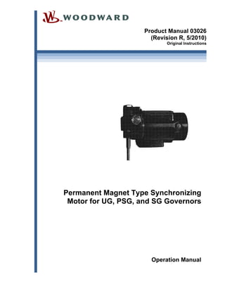
  • 1. Product Manual 03026 (Revision R, 5/2010) Original Instructions Permanent Magnet Type Synchronizing Motor for UG, PSG, and SG Governors Operation Manual
  • 2. General Precautions Read this entire manual and all other publications pertaining to the work to be performed before installing, operating, or servicing this equipment. Practice all plant and safety instructions and precautions. Failure to follow instructions can cause personal injury and/or property damage. Revisions This publication may have been revised or updated since this copy was produced. To verify that you have the latest revision, check manual 26311 , Revision Status & Distribution Restrictions of Woodward Technical Publications, on the publications page of the Woodward website: www.woodward.com/publications The latest version of most publications is available on the publications page. If your publication is not there, please contact your customer service representative to get the latest copy. Proper Use Any unauthorized modifications to or use of this equipment outside its specified mechanical, electrical, or other operating limits may cause personal injury and/or property damage, including damage to the equipment. Any such unauthorized modifications: (i) constitute "misuse" and/or "negligence" within the meaning of the product warranty thereby excluding warranty coverage for any resulting damage, and (ii) invalidate product certifications or listings. Translated Publications If the cover of this publication states "Translation of the Original Instructions" please note: The original source of this publication may have been updated since this translation was made. Be sure to check manual 26311 , Revision Status & Distribution Restrictions of Woodward Technical Publications, to verify whether this translation is up to date. Out-of-date translations are marked with . Always compare with the original for technical specifications and for proper and safe installation and operation procedures. Revisions—Changes in this publication since the last revision are indicated by a black line alongside the text. Woodward reserves the right to update any portion of this publication at any time. Information provided by Woodward is believed to be correct and reliable. However, no responsibility is assumed by Woodward unless otherwise expressly undertaken. Manual 03026 Copyright © Woodward 1991–2010 All Rights Reserved
  • 3. Manual 03026 Permanent Magnet Synchronizing Motor Woodward 1 Warnings and Notices Important Definitions This is the safety alert symbol. It is used to alert you to potential personal injury hazards. Obey all safety messages that follow this symbol to avoid possible injury or death.  DANGER—Indicates a hazardous situation which, if not avoided, will result in death or serious injury.  WARNING—Indicates a hazardous situation which, if not avoided, could result in death or serious injury.  CAUTION—Indicates a hazardous situation which, if not avoided, could result in minor or moderate injury.  NOTICE—Indicates a hazard that could result in property damage only (including damage to the control).  IMPORTANT—Designates an operating tip or maintenance suggestion. Overspeed / Overtemperature / Overpressure The engine, turbine, or other type of prime mover should be equipped with an overspeed shutdown device to protect against runaway or damage to the prime mover with possible personal injury, loss of life, or property damage. The overspeed shutdown device must be totally independent of the prime mover control system. An overtemperature or overpressure shutdown device may also be needed for safety, as appropriate. Personal Protective Equipment The products described in this publication may present risks that could lead to personal injury, loss of life, or property damage. Always wear the appropriate personal protective equipment (PPE) for the job at hand. Equipment that should be considered includes but is not limited to:  Eye Protection  Hearing Protection  Hard Hat  Gloves  Safety Boots  Respirator Always read the proper Material Safety Data Sheet (MSDS) for any working fluid(s) and comply with recommended safety equipment. Start-up Be prepared to make an emergency shutdown when starting the engine, turbine, or other type of prime mover, to protect against runaway or overspeed with possible personal injury, loss of life, or property damage. Automotive Applications On- and off-highway Mobile Applications: Unless Woodward's control functions as the supervisory control, customer should install a system totally independent of the prime mover control system that monitors for supervisory control of engine (and takes appropriate action if supervisory control is lost) to protect against loss of engine control with possible personal injury, loss of life, or property damage.
  • 4. Permanent Magnet Synchronizing Motor Manual 03026 2 Woodward Battery Charging Device To prevent damage to a control system that uses an alternator or battery-charging device, make sure the charging device is turned off before disconnecting the battery from the system. Electrostatic Discharge Awareness Electrostatic Precautions Electronic controls contain static-sensitive parts. Observe the following precautions to prevent damage to these parts:  Discharge body static before handling the control (with power to the control turned off, contact a grounded surface and maintain contact while handling the control).  Avoid all plastic, vinyl, and Styrofoam (except antistatic versions) around printed circuit boards.  Do not touch the components or conductors on a printed circuit board with your hands or with conductive devices. To prevent damage to electronic components caused by improper handling, read and observe the precautions in Woodward manual 82715, Guide for Handling and Protection of Electronic Controls, Printed Circuit Boards, and Modules. Follow these precautions when working with or near the control. 1. Avoid the build-up of static electricity on your body by not wearing clothing made of synthetic materials. Wear cotton or cotton-blend materials as much as possible because these do not store static electric charges as much as synthetics. 2. Do not remove the printed circuit board (PCB) from the control cabinet unless absolutely necessary. If you must remove the PCB from the control cabinet, follow these precautions:  Do not touch any part of the PCB except the edges.  Do not touch the electrical conductors, the connectors, or the components with conductive devices or with your hands.  When replacing a PCB, keep the new PCB in the plastic antistatic protective bag it comes in until you are ready to install it. Immediately after removing the old PCB from the control cabinet, place it in the antistatic protective bag.
  • 5. Manual 03026 Permanent Magnet Synchronizing Motor Woodward 3 Permanent Magnet Synchronizing Motor for UG, PSG, and SG Governors Description The permanent-magnet synchronizing motor is used to provide remote speed adjustment for an SG, PSG, or UG governor. The motor allows a switchboard operator to match the frequency of an alternator to that of other alternators or to change load distribution with other units when operating in the droop mode. The synchronizing motors run only on nominal 24 Vdc power, but models are available with self-contained rectifiers which allow use of 110 Vac and 220 Vac supply. A potentiometer is included in most models. This allows the installer to match the motor with the type of supply available, and to set the motor speed within an adjustable range. Four different PM motors have been used to adjust the speed setting of the governor. The S40, MM40, and MM4A have been used in the past. The current model is the SMM40. The SMM40 is directly interchangeable with any former speed-setting motor. The SMM40 permanent-magnet motor operates on a nominal 24-Vdc supply. Rectifiers are included in models built to operate with ac supply. In addition a potentiometer is included with the unit which adjusts dc voltages to an acceptable level. An adjustable speed is achieved when a PM or APM motor control is added to the system. SMM40 Speed POWER RATED SPEED (RPM) ADJUSTABLE RANGE (RPM)* 24 Vdc 1 2 4 8 0.5 to 1.2 1.2 to 2.5 2.5 to 5 5 to 10 110 Vac/dc 0.5 3 6 0.5 to 1 1 to 4 4 to 9 220 Vac/dc 0.5 3 6 0.5 to 1 1 to 4 4 to 9 * An adjustable range is available when an APM or PM motor control is used. The adjustment range is only for reference. Exact range depends on the controller used. Product Specifications 82044 APM Motor Control 82499 Adjustable Voltage Converter for 24 Vdc PM Motor Control
  • 6. Permanent Magnet Synchronizing Motor Manual 03026 4 Woodward Adjustment A friction-type slip clutch between the motor shaft and the governor allows speed adjustment by the regular manual speed-setting method or by the electrically- driven PM motor. If this coupling has too little friction the motor drive will slip. With too great friction the manual speed adjustment will be too hard to turn or set. The slip clutch also prevents damage to the governor or the speed adjusting motor when a maximum or minimum stop is attained. (The motor can continue to run for a short period after a physical stop has been reached.) The clutch should be adjusted for about 0.5 Nm (4.5 lb-in) of friction. Individual governor manuals contain instructions on the maintenance and setting of the friction clutch. Adjustment Procedure (There are no adjustments on the MM4A.) 1. Unscrew the four round head screws (828, 515, 605) that hold the cover plate (825, 519, 602) on the potentiometer portion of the unit. 2. Loosen the lock nut (866, 511, 603) on the potentiometer, turning it counterclockwise. Turn the potentiometer adjusting shaft (865, 608, 530) clockwise (toward F on the Bakelite board (834, 510, 601) to increase motor speed, or counterclockwise (toward S) to decrease motor speed. When the slot in the shaft points toward the white spot on the Bakelite board the potentiometer adjustment will be at about the rated speed. 3. After the adjustment has been satisfactorily completed, lock the nut on the shaft and replace the cover and four round-head screws removed in step 1 of this procedure. (Do not operate the engine for any extended period of time with the potentiometer and wiring exposed.) Power Connection If ac power is used for speed adjustment connect one line from the ac source to terminal "C" on the receptacle (831, 522, 609). The rectifiers (843, 518, 606) may burn out if the unit is incorrectly wired. (Review the wiring diagram on the next page and check against the wiring before applying power to the motor for the first time.) Terminals "A" and "B" are connected to the respective output poles of the speed- control switch. Bearing Lubrication Ball bearings are permanently packed with a high-quality grease. Repacking or periodic oiling is not required.
  • 7. Manual 03026 Permanent Magnet Synchronizing Motor Woodward 5 Gear Lubrication The speed reduction gear housing (846, 528, 640, 733) is filled with enough lubricant to last about two years. Clean out the old grease every two years or as required and refill with Alvania No. 2 grease or its equivalent. Wiring Diagrams Power Connection Diagram
  • 8. Permanent Magnet Synchronizing Motor Manual 03026 6 Woodward Troubleshooting The speed setting motor is extremely long lived and reliable. Most problems perceived as caused by the motor are in reality caused by either the power supply to the motor or the friction clutch and speed-setting linkage in the governor. Do not disassemble the motor until after all other causes have been thoroughly investigated. Make sure that the correct power is being delivered to the motor. Check the connection between the motor and the power source. Excess load or low supply voltage will slow the speed of the motor. Motor load can be caused in the governor as well as in the sealed gears on the motor. Always check for load in the governor by trying to turn the manual speed setting knob before assuming that excess load is in the motor and attached gears. Motor heat can be caused by low voltage, excess load, or internal wiring. Always check causes outside of the motor before determining that the motor is at fault. Applied voltage can cause motor overspeed. Overspeed conditions are seldom caused by the motor itself. Irregular motor speed can be caused by a slipping clutch, problems in the voltage supply to the motor, of by the motor itself. Trouble Cause Correction Motor will not operate No applied voltage Power source or motor speed controller incorrect. Adjust or exchange power source or controller. Fuses are blown. Replace fuse, investigate cause. Wiring has intermittent open condition. Correct wiring. Applied voltage time is too short. Minimum signal time of 0.2 seconds for motor response. Current off Brush spring or wire disconnection. Replace spring or correct wire. Brush incorrectly installed. Correctly install brush. Overload, Overcurrent Speed-setting gear in governor is locked up. Inspect and correct governor. Excessive wear in speed-setting bearings. Replace bearings. Motor reduction gears. Adjust or replace reduction gears. Low rpm (motor speed) Low Voltage Power source to motor-speed controller incorrect. Adjust or exchange power source or speed controller. Low Voltage Control Voltage incorrect. Correct supply voltage. Low Motor Torque Brush spring disconnecting or shorting. Replace brush and spring. Insulation incorrect. Clean around brush holder or replace motor windings. Overload Motor shaft has overloaded. Inspect governor connection and speed setting mechanism. Reduction gear box troubles. Inspect reduction gear box. Replace grease or parts as necessary. Bearing wear, lubrication, or adjustment. Replace bearings, lubricate, and adjust as necessary.
  • 9. Manual 03026 Permanent Magnet Synchronizing Motor Woodward 7 Trouble Cause Correction Low rpm Low Voltage Power source or motor speed controller incorrect. Adjust or exchange power source. Voltage incorrect. Check rated voltage, adjust or exchange power source. Low motor torque Motor fault. Repair motor or exchange motor. Insulation incorrect. Clean around brush holder and brush spring. Overload Motor shaft has overload. Inspect governor. Reduction gear box problem. Inspect and repair reduction gear box. Change lubrication in gear box. Bearings worn. Replace bearings. High rpm High voltage Power source or motor speed controller incorrect. Adjust or replace power source or motor speed controller. Voltage incorrect Check rated voltage. Provide correct voltage to the motor. Unstable motor speed Current is changing Load is changing. Inspect governor, inspect gear box. Speed controller is not functioning correctly. Inspect and repair or replace controller. Bearing trouble. Replace or adjust bearings. Brush spring disconnecting or shorting. Replace spring, inspect installation of brush and spring. Dirt between brush and commutator. Inspect brush, clean commutator. Motor is over- heating Overcurrent Overload. Repair governor, gear box, or bearings. Bearing problem. Replace bearing. Excessive bearing thrust. Adjust bearing thrust. Failed brush spring insulation, short. Replace brush spring, check installation of spring and brush. Brush holder shorting. Clean around brush holder. Motor is overheating High ambient temperature condition. Improve ventilation, reduce ambient temperature. Motor is dirty. Clean motor to improve heat- exchange capabilities. Excessive brush wear Commutation incorrect Overload. Repair governor, gear box, or bearing. Abrasive gas in atmosphere. Ventilate with clean air. Damaged commutator. Polish commutator, replace armature assembly. Brush spring tension incorrect or brush spring is shorting. Replace the spring, check the brush installation. Excessive vibration. Improve mounting or reduce governor vibration. Brush material incorrect Brush does not match motor characteristics or installation conditions. Change brush composition or change operating conditions. Motor operation is noisy Excessive vibration Incorrect motor installation. Correct installation. Motor drive alignment incorrect. Correct alignment. Dirt or debris in the gap between the commutator and the brush. Clean or repair motor. Motor operation is noisy cont. Bearings causing vibration Lubrication error. Replace bearing and correct lubrication. Damaged bearing surface. Replace bearing and correct lubrication and adjustment. Bearing seizure. Replace bearing and correct lubrication and adjustment. Commutator damaged, causing damage to the brush Damaged or worn commutator. Repair commutator or replace armature and winding assembly. Abrasive atmosphere. Improve ventilation or change brush components to match demands of the atmosphere.
  • 10. Permanent Magnet Synchronizing Motor Manual 03026 8 Woodward Replacement Parts The following pages list replacement parts for the four speed-setting motors included in this manual. The user must be careful that the illustration and parts list correctly matches the motor being serviced. A number of parts are identified in the drawings for information only. These parts are available only through the purchase of larger assemblies, usually the complete motor assembly. When ordering replacement parts, include the following information: 1. Serial number and part number shown on the mane plate. 2. Manual number (this is Manual 03026). 3. Part number from parts list and description or part name. Do not replace the motor until failure of the remote speed-setting adjustment is clearly identified as failure of the motor. Check wiring to the motor and power to the motor before assuming that the motor has failed. If the electrical supply to the motor is determined to be correct, then carefully check the slip-clutch setting to be sure that it has not changed. Check the manual speed-setting gear train to be sure it is not presenting too great a load for the motor to turn.
  • 11. Manual 03026 Permanent Magnet Synchronizing Motor Woodward 9 Model S40 Specify Model S40 when ordering parts from this page. Note that the part numbers are for identification only and are not Woodward part numbers. Ref. No. Part Name............. Quantity 03026-501 Motor Brush ........................2 03026-502 Brush Spring.......................2 03026-503 Ball Bearing ........................1 03026-504 Ball Bearing ........................1 03026-505 End Housing .......................1 03026-506 Armature.............................1 03026-507 *Ferrite Magnet...................1 03026-508 Potentiometer .....................1 03026-509 *Frame................................1 03026-510 Bakelite Board ....................1 03026-511 Nut......................................1 03026-512 Cross Bar............................1 03026-513 Spring Washer....................4 03026-514 Screw..................................4 03026-515 Screw..................................1 03026-516 Stop Ring............................1 03026-517 Vinyl Washer ......................1 Ref. No. Part Name .............Quantity 03026-518 Rectifier .............................. 2 03026-519 Enclosing Cover ................. 1 03026-520 Plug.................................... 1 03026-521 Cable Clamp....................... 1 03026-522 Receptacle ......................... 1 03026-523 Condenser.......................... 1 03026-524 Worm Gear Shaft ............... 1 03026-525 Bakelite Gear...................... 1 03026-526 Bronze Gear....................... 1 03026-527 Output Shaft ....................... 1 03026-528 *Reduction Gear Box.......... 1 03026-529 Sleeve ................................ 2 03026-530 *Adjusting Shaft.................. 1 03026-531 Screw ................................. 3 03026-532 Nut...................................... 3 03026-533 Washer............................... 3 * Parts available only in connection with larger assembly.
  • 12. Permanent Magnet Synchronizing Motor Manual 03026 10 Woodward Model MM40 (Speed Setting serial numbers 21105 and after are model MM40. Note that the part numbers are for identification only and are not Woodward part numbers. Ref. No. Part Name .............Quantity 03026-601 Bakelite Board.................... 1 03026-602 Pot Cover ........................... 1 03026-603 Potentiometer..................... 1 03026-604 Rd Hd Screw.................... 12 03026-605 Spring Washer ................. 14 03026-606 Rectifier.............................. 2 03026-607 Flat Washer........................ 6 03026-608 Gasket................................ 1 03026-609 Receptacle ......................... 1 03026-610 Plug.................................... 1 03026-611 Cable Clamp ...................... 1 03026-612 Condenser.......................... 1 03026-613 Ball Bearing........................ 1 03026-614 Rd Hd Screw...................... 2 03026-615 Alum. Washer..................... 1 03026-616 Retaining Ring.................... 1 03026-617 Bearing Retainer ................ 1 03026-618 Brush Holder Board............ 1 03026-619 End Cover .......................... 1 03026-620 Motor Brush........................ 2 03036-620A Brush Holder Assy.............. 1 03026-621 Brush Spring ...................... 2 03026-622 *Bracket.............................. 1 03026-623 Armature Assy.................... 1 03026-624 *Ferrite Magnet .................. 1 03026-625 *Stator Assy ....................... 1 Ref. No. Part Name ............. Quantity 03026-626 *Body ..................................1 03026-627 Ball Bearing ........................1 03026-628 Alum Washer ......................1 03026-629 Bearing Cap........................1 03026-630 Retaining Ring ....................1 03026-631 Bearing Retaining Ring.......1 03026-632 *Pot. Box.............................1 03026-633 Gasket ................................1 03026-634 Plate....................................1 03026-635 Name Plate .........................1 03026-636 Grommet.............................1 03026-637 Worm Shaft.........................1 03026-638 Helical Gear ........................1 03026-639 Rd Hd Screw......................... 03026-640 *Gear Housing ....................1 03026-641 Oil Seal ...............................1 03026-642 Output Shaft........................1 03026-643 Helical Gear ........................1 03026-644 Fiber Washer ......................3 03026-645 Lock Nut..............................3 03026-646 Adjusting Plug.....................3 03026-647 Ball......................................3 03026-648 Ball Seat .............................1 03026-649 Damping Bushing................1 03026-650 Rd Hd Screw.......................4 NOTE—Units with the Damping Rubber Bushing use 8 parts 604 and 10 parts 607. * Parts available only in connection with larger assembly.
  • 13. Manual 03026 Permanent Magnet Synchronizing Motor Woodward 11 Model MM4A This model does not include built in rectifiers or a voltage adjustment potentiometer. Note that the part numbers are for identification only and are not Woodward part numbers. Ref. No. Part Name............. Quantity 03026-701 *Front Housing....................1 03026-702 *Body..................................1 03026-703 *Stator Assembly ................1 03026-704 *Ferrite Magnet...................1 03026-705 *Retaining Ring...................1 03026-706 *Rd Hd Screw .....................2 03026-707 *Spring Washer...................2 03026-708 *Flat Washer.......................2 03026-709 Bearing Cap........................1 03026-710 Retaining Ring ....................1 03026-711 Alum Washer ......................1 03026-713 Alum Washer ......................2 03026-714 Bearing Retainer.................1 03026-715 Bearing Retainer.................1 03026-716 Ball Bearing ........................1 03026-717 Ball Bearing ........................1 03026-718 Condenser ..........................1 03026-719 *Insulator ............................1 03026-720 *Motor Cover ......................1 03026-721 *Rd Hd Screw .....................2 03026-722 *Armature ...........................1 03026-723 Brush Holder Assy..............1 03026-724 Motor Brush ........................2 03026-725 Brush Spring.......................2 03026-726 *Rd Hd Screw .....................2 Ref. No. Part Name .............Quantity 03026-727 *Grommet........................... 1 03026-728 Name Plate ........................ 1 03026-729 Brush Holder Board............ 1 03026-730 Worm Shaft ........................ 1 03026-731 Helical Gear........................ 1 03026-732 Rd Hd Screw ...................... 1 03026-733 Gear Housing ..................... 1 03026-734 Oil Seal............................... 1 03026-735 Output Shaft ....................... 1 03026-736 Helical Gear........................ 1 03026-737 Fiber Washer...................... 3 03026-738 Lock Nut ............................. 3 03026-739 Adjusting Plug .................... 3 03026-740 Ball ..................................... 3 03026-741 Ball Seat............................. 3 03026-742 *Cover ................................ 1 03026-752 *Name Plate ....................... 1 03026-753 *Plate.................................. 1 03026-754 Rd Hd Screw ...................... 4 03026-755 Gasket................................ 1 03026-756 Rd Hd Screw ...................... 4 03026-757 Plug.................................... 1 03026-758 Cable Clamp....................... 1 03026-759 Screw ................................. 4 03026-760 *Box.................................... 1 * Parts available only in connection with larger assembly.
  • 14. Permanent Magnet Synchronizing Motor Manual 03026 12 Woodward Model SMM40 This motor will replace any other speed-setting motor. Most parts, however, are not interchangeable. Note that the part numbers are for identification only and are not Woodward part numbers. Housing is IP44.  
  • 15. Manual 03026 Permanent Magnet Synchronizing Motor Woodward 13 Ref. No. Part Name............. Quantity 03026-801 *Front Housing....................1 03026-802 *Body..................................1 03026-803 *Stator Assy........................1 03026-804 PH Hd Screw ......................2 03026-805 Spring Washer....................2 03026-806 Retaining Ring ....................1 03026-807 Retaining Ring ....................1 03026-808 Cap.....................................1 03026-809 Alum Washer ......................2 03026-810 Alum Washer ......................2 03026-811 Bearing Retainer.................1 03026-812 Bearing Retainer.................1 03026-813 Ball Bearing ........................1 03026-814 Ball Bearing ........................1 03026-815 Holder Cap .........................2 03026-816 Brush Assy .........................2 03026-817 *Brush Holder .....................2 03026-818 *Grommet ...........................1 03026-819 Lead Wire ........................AR 03026-820 Armature.............................1 03026-821 PH Hd Screw ............ max 10 03026-822 Flat Washer ........................2 03026-823 Set Screw ...........................1 03026-824 *Potentiometer Box.............1 03026-825 Potentiometer Cover...........1 03026-826 Gasket ................................1 03026-827 Gasket ................................1 03026-828 Removed 03026-829 Removed 03026-830 PH Hd Screw ...............3 or 4 03026-831 Receptacle..........................1 03026-832 Plug & Cable Clamp ...........1 03026-833 Removed 03026-834 Bakelite Board ....................1 03026-835 Potentiometer .....................1 03026-836 Damping Bushing ...............8 03026-837 Slotted Hd Screw................4 03026-838 Insulated Terminal ..............2 03026-839 Spring Washer....................1 03026-840 Pan Hd Screw.....................5 03026-841 Spring Lock Washer ...........5 03026-842 Terminal..............................5 Ref. No. Part Name .............Quantity 03026-843 Diode Rectifier.................... 2 03026-844 Plate................................... 1 03026-845 *Grommet........................... 1 03026-846 *Gear Housing.................... 1 03026-847 Bushing .............................. 4 03026-848 Motor Shaft......................... 1 03026-849 Ball Seat............................. 3 03026-850 Hex Nut .............................. 3 03026-851 Shim................................... 3 03026-852 Fiber Washer...................... 3 03026-853 Worm Gear Shaft ............... 1 03026-854 Helical Gear........................ 1 03026-855 Helical Gear........................ 1 03026-856 Oil Seal............................... 2 03026-857 Screw ................................. 1 03026-858 Screw ................................. 2 03026-859 Screw ................................. 2 03026-860 Washer............................... 3 03026-861 Spacer................................ 1 03026-862 Spacer................................ 1 03026-863 Retainer.............................. 1 03026-864 Ball ..................................... 3 03026-865 Nameplate.......................... 1 03026-866 Terminal Block.................... 1 03026-867 Bakelite Board.................... 1 03026-868 PH Hd Screw...................... 4 03026-869 Hex Nut .............................. 4 03026-870 Sleeve ................................ 1 03026-871 Removed 03026-872 PH Hd Screw...................... 1 03026-873 Gland Lock Nut................... 1 03026-874 Gland Packing.................... 1 03026-875 Gland Lock Union............... 1 03026-876 Gland Nut ........................... 1 03026-877 Gland Lock Joint................. 1 03026-878 Motor Label ........................ 1 03026-879 Cable Clamp Bushing......... 1 03026-880 Board.................................. 1 03026-881 Insulated Terminal.............. 1 03026-882 Bearing Cap ....................... 1 03026-883 O-ring ................................. 1 03026-884 Gasket................................ 1 * Parts available only in connection with larger assembly.
  • 16. We appreciate your comments about the content of our publications. Send comments to: icinfo@woodward.com Please reference publication 03026R. PO Box 1519, Fort Collins CO 80522-1519, USA 1000 East Drake Road, Fort Collins CO 80525, USA Phone +1 (970) 482-5811  Fax +1 (970) 498-3058 Email and Website—www.woodward.com Woodward has company-owned plants, subsidiaries, and branches, as well as authorized distributors and other authorized service and sales facilities throughout the world. Complete address / phone / fax / email information for all locations is available on our website.