Download to read offline


![3 Electrical Installation
12 I80E-EN J1000 Quick Start Guide
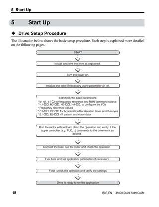
Wiring Specification
Main Circuit
Use the fuses and line filters listed up in the table below when wiring the main circuit. Make
sure not to exceed the given tightening torque values.
Tightening Torque Values
Tighten the main circuit terminals using the torque values provided by the table below.
Control Circuit
Use wires within the specification listed below. For safe wiring use solid wires or flexible
wires with ferrules. The stripping length or ferrule length should be 6 mm.
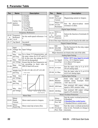
Model
JZA
EMC Filter Type
Main Fuse
(Ferraz)
Recom.
Motor cable
[mm²]
Main Circuit Terminal Sizes
Schaffner
R/L1,S/L2,T/L3, U/T1,
V/T2,W/T3, - , +1, +2 B1, B2 GND
B0P1
A1000-FIV1010-SE
A6T15 2.5 M3.5 M3.5 M3.5
B0P2 A6T20 2.5 M3.5 M3.5 M3.5
B0P4 A6T20 2.5 M3.5 M3.5 M3.5
B0P7
A1000-FIV1020-SE
A6T40 2.5 M4 M4 M4
B1P5 A6T40 4 M4 M4 M4
20P1
A1000-FIV2010-SE
A6T10 2.5 M3.5 M3.5 M3.5
20P2 A6T10 2.5 M3.5 M3.5 M3.5
20P4 A6T15 2.5 M3.5 M3.5 M3.5
20P7 A6T20 2.5 M3.5 M3.5 M3.5
21P5
A1000-FIV2020-SE
A6T25 2.5 M4 M4 M4
22P2 A6T30 4 M4 M4 M4
24P0 A1000-FIV2030-SE A6T40 6 M4 M4 M4
40P2
A1000-FIV3005-SE
A6T10 2.5 M4 M4 M4
40P4 A6T10 2.5 M4 M4 M4
40P7 A6T20 2.5 M4 M4 M4
41P5
A1000-FIV3010-SE
A6T25 2.5 M4 M4 M4
42P2 A6T25 2.5 M4 M4 M4
43P0 A6T25 2.5 M4 M4 M4
44P0 A1000-FIV3020-SE A6T30 2.5 M4 M4 M4
Terminal Size M3.5 M4
Tightening Torque [Nm] 0.8 to 1.0 1.2 to 1.5
Terminal Screw Size
Tightening
Torque N·m
Bare Wire Terminal Ferrule-Type Terminal
Applicable wire
size mm2
Recomm.
mm2
Applicable wire
size mm2
Recomm.
mm2
MA, MB, MC M3 0.5 to 0.6 0.25 to 1.5 0.75 0.25 to 1.0 0.5
S1-S5, SC, +V, A1,
AC, AM
M2 0.22 to 0.25 0.25 to 1.0 0.75 0.25 to 0.5 0.5](https://image.slidesharecdn.com/j1000quickstartguide-140613042705-phpapp02/85/J1000-quickstartguide-13-320.jpg)


This document provides a quick start guide for the OMRON J1000 compact general purpose inverter. It includes sections on safety instructions, mechanical installation, electrical installation, keypad operation, start up, parameter settings, and troubleshooting. The guide specifies the drive can be used for 200V class, three-phase input models from 0.1 to 4 kW, 200V class single-phase input from 0.1 to 1.5 kW, and 400V class three-phase input from 0.2 to 4 kW. It also provides mounting dimensions and environmental operating conditions.


![Ct2000 pro plus_manual_english[1]](https://cdn.slidesharecdn.com/ss_thumbnails/ct2000proplusmanualenglish1-140613213527-phpapp02-thumbnail.jpg?width=640&height=640&fit=bounds)


![Ct2000 es manual_english_version_1[1].0](https://cdn.slidesharecdn.com/ss_thumbnails/ct2000esmanualenglishversion11-140613213448-phpapp01-thumbnail.jpg?width=640&height=640&fit=bounds)


