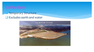
1. The document discusses various design considerations and components for cofferdams, including overall stability, bottom failure prevention, protection from aggressive site conditions, and load transfer mechanisms.
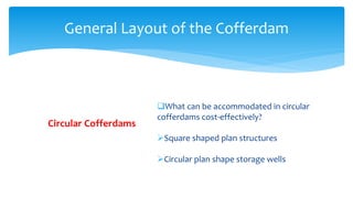
2. It describes different types of cofferdams like circular and rectilinear designs and their components like sheet piling, bracing methods using waling, anchors, and struts.
3. Failure reasons like poor workmanship, inadequate sections, and lack of embedment are outlined. Design of anchors, struts, walling, and protection from scouring are covered.