
Recommended
Recommended
More Related Content
What's hot
What's hot (20)
Similar to A overview on WAMS/PMU.
Similar to A overview on WAMS/PMU. (20)
Recently uploaded
Recently uploaded (20)
A overview on WAMS/PMU.
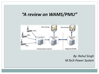
- 1. “A review on WAMS/PMU” By: Rahul Singh M.Tech Power System
- 2. INTRODUCTION The modern-day power grid aims at providing reliable and quality power, which requires careful monitoring of the power grid against catastrophic faults. As power grid is moving from the traditional to smart grid, the operation of grid becomes more complex Renewable Energy Resources ,Electric-Vehicles increasing rapidly therefore synchronization of grid become more complex problem. Also present power system is operating near to its stability limits if sudden increase/decrease in demand happens , will result in grid failure/collapse.
- 3. TO PROTECT POWER SYSTEM FROM COLLAPSE? One promising way is to provide the system a wide protection and control named as “Wide Area Measurement and Control System”. The WAMS consists of several sensors known as the phasor measurement units (PMUs) that collect the real information pertaining to the health of the power grid PMUs are the most accurate and advanced synchronized measurement technology available.
- 4. WIDE AREA MONITORING SYSTEM (WAMS) It is a collective technology to monitor power system dynamics in real time and also to identify system stability related weakness and helps to design and implement counter measures.(IEEE) WAMS uses a GPS satellite signals to time-synchronize from phasor measurement units at important nodes in the Power System, sends real time phasors data to a Control Centre. The acquired phasor data provide dyanamic information on power systems, which help operators to initiate corrective actions to enhance the power system reliability.
- 6. PHASOR MEASUREMENT UNIT (PMU) PHASOR DATA CONCENTRATOR (PDC) SYNCHROPHASOR COMMUNICATION CHANNEL. WAMS COMPONENTS
- 7. The heart of the WAMS technology is are Phasor Measurement Unit i.e. a PMU
- 8. WHAT IS PHASOR? Phasor is a quantity with magnitude and phase (with respect to a reference) that is used to represent a sinusoidal signal. Here the phase or phase angle is the distance between the signal’s sinusoidal peak and a specified reference and is expressed using an angular measure. Here, the reference is a fixed point in time (such as time = 0). The phasor magnitude is related to the amplitude of the sinusoidal signal
- 9. SYNCHROPHASOR A synchrophasor is a phasor measurement with respect to an absolute time reference. With this measurement we can determine the absolute phase relationship between phase quantities at different locations on the power system.
- 10. WHAT IS PHASOR MEASUREMENT UNIT? IEEE Defination “Phasor measurement unit (PMU): A device that produces synchronized phasor ,frequency, and rate of change of frequency (ROCOF) estimates from voltage and/or current signals and a time synchronizing signal”. Time synchronization is usually provided by GPS and allows synchronized real-time measurements of multiple remote points on the grid. PMUs are capable of capturing samples from a wave form in quick succession and reconstructing the phasor quantity, made up of an angle measurement and a magnitude measurement. The resulting measurement is known as a synchrophasor. These time synchronized measurements are important because if the grids supply and demand are not perfectly matched, frequency imbalances can cause stress on the grid, which is a potential cause for power outages.
- 11. CONTINUE... PMUs can also be used to measure the frequency in the power grid. A typical commercial PMU can report measurements with very high temporal resolution in the order of 30-60 measurements per second. This helps engineers in analyzing dynamic events in the grid which is not possible with traditional SCADA measurements that generate one measurement every 2 or 4 seconds. Therefore, PMUs equip utilities with enhanced monitoring and control capabilities and are considered to be one of the most important measuring devices in the future of power systems. A PMU can be a dedicated device,or the PMU function can be in corporated in to a protective relay or other device.
- 12. THE MAIN COMPONENTS OF PMU Analog Inputs GPS receiver Phase locked oscillator A/D converter Anti-aliasing filters Phasor micro-processor Modem
- 13. FUNCTIONAL BLOCKS IN PMU
- 14. ANALOG INPUT Current and potential transformers are employed at substation for measurement of voltages and current. The analog inputs to the PMU are the voltages and currents obtained from the secondary winding of potential and current transformers.
- 15. ANTI-ALIASING FILTER Anti-aliasing filter is an analog low pass filter which is used to filter out those components from the actual signal whose frequencies are greater than or equal to half of nyquist rate to get the sampled waveform. Nyquist rate is equal to twice the highest frequency component of input analog signal. If antialiasing filters are not used, error will be introduced in the estimated phasor
- 16. PHASE LOCK OSCILLATOR Phase lock oscillator along with Global Positioning System reference source provides the needed high speed synchronized sampling. Global Positioning System (GPS) is a satellite-based system for providing position and time.
- 17. A/D CONVERTER It converts the analog signal to the digital signal. Quantization of the input involves in ADC that introduces a small amount of error. The output of ADC is a sequence of digital values that convert a continuous time and amplitude analog signal to a discrete time and discrete amplitude signal. It is therefore required to define the rate at which new digital values are sampled from the analog signal. The rate of new values at which digital values are sampled is called the sampling rate of the converter.
- 18. GLOBAL POSITIONING SYSTEM The synchronized time is given by GPS uses the high accuracy clock from satellite technology. Without GPS providing the synchronized time, it is hard to monitor whole grid at the same time. The GPS satellites provide a very accurate time synchronization signal ,available,via an antenna input, throughout the power system.This means that that voltage and current recordings from different substations can be directly displayed on the same time axis and in the same phasor diagram.
- 19. PROCESSOR The microprocessor calculates positive-sequence estimates of all the current and voltage signals using the DFT techniques. Certain other estimates of interest are frequency and rate of change of frequency measured locally, and these also are included in the output of the PMU. The time stamp is created from two of the signals derived from the GPS receiver. The time-stamp identifies the identity of the “universal time coordinated (UTC) second and the instant defining the boundary of one of the power frequency periods.
- 20. MODEM A device that modulates an analog carrier signal and encodes digital information from the signal and can also demodulate the signal to decode the transmitted information from signal is called modem. The objective of modem is to produce a signal that can be transmitted and decoded to make a replica of the original digital data. Modem can be used with no means of transmitting analog signals
- 21. APPLICATION OF PMU IN POWER SYSTEM Adaptive relaying Instability prediction State estimation Improved control Fault recording Disturbance recording Transmission and generation modeling verification Wide area Protection Fault location
- 22. PHASOR DATA CONCENTRATOR (PDC) A PDC works as a node in a communication network The main function of this PDC are to gather data from several PMUs, PDC will receive the voltage current phasor information along with the frequency also from the PMUs, to reject the bad data. The PDC can exchange the data and commands with PMUs and also with other PDCs. It receives data from multiple PMUs, performs a check on the received data, time aligns the data and creates an output stream. The communication links are basically bidirectional, most of the data flows upward in hierarchy , although there are some tasks which require communication capability in reverse direction. Usually these commands for configuring the downstream components, requesting data in a particular form, etc
- 25. SYNCHROPHASOR COMMUNICATION TECHNOLOGIES As the signal is time stamped, it is transmitted from the PMU to the PDC through the synchrophasor communication network. The key communication technologies , for synchrophasor data transfer, can be broadly classified into two categories: 1. Wired 2. Wireless.
- 26. The wired communication technology offers high reliability, huge bandwidth and protection against interference. On the other hand, wireless technology enjoys superiority in terms of rapid deployment, low installation and maintenance costs, access to remote geographic locations, etc.
- 27. SYNCHROPHASOR COMMUNICATION TECHNOLOGIES in PMUs Wired Communication Channel Power Line Communication Fibre Optic Communication Wireless Communication Channel Microwave Communication Cellular communication Satellite Communication
- 30. Power Line Communication (PLC) uses the existing power line cables for the transfer of synchrophasor data, this technology provides the fastest and economical means for the deployment of communication networks. There are two types of PLC technologies: 1. Narrow Band PLC (NB-PLC) ,used for low bandwidth applications 2. Broad Band PLC (BB-PLC) , used for applications requiring higher bandwidth. As the synchrophasor application is mission critical, BB-PLC would be the preferred choice. Typical data rates ranging from 2 to 3 Mbps can be achieved using this technology. In spite of having several advantages, the technology suffers from many disadvantages such as the difficulty in modeling the communication channel due to the noisy background in the power cables. Moreover, the PLC is not meant for high bandwidth applications due to fading and interference. The signal to noise ratio (SNR) is low and this technology is usually combined with other communication technologies, such as cellular communication, to provide a hybrid solution for power grid communications.
- 31. FIBRE OPTIC COMMUNICATION This communication channel used for long-distance communication The high data rates, low attenuation, high reliability and negligible interference made them a widely used synchrophasor communication technology
- 32. The data received from the PMU is converted into an optical signal by the optical transmitter, which is basically a light emitting diode or a laser. These optical signals are then carried via the optical fibers to the PDC. At the PDC, the optical signal is converted back into electrical signals using a photodiode. Between the PMU and the PDC, optical repeaters are placed at regular intervals to boost the signal strength and to maintain the signal quality.
- 35. With the growth of wireless technology, the transfer of data in Gbps are being achieved. Thus, this technology provides a viable alternative to the optical fiber SPCS. In the microwave communication, the synchrophasor data generated by the PMU is fed to a PMU radio terminal that converts the electrical signal into radio frequency (RF) signal. The RF signal is then fed to a microwave antenna that converts the RF signal into an electromagnetic signal. This electromagnetic signal propagates in free space and is received by the microwave antenna at the PDC. The PDC radio terminal converts the RF signal back into the electrical signal, which is sent to the PDC for analysis. Intermediate repeaters are required to maintain the signal strength and to ensure communication feasibility in the case of non-line of sight propagation.
- 36. CELLULAR COMMUNICATION It is one of the fastest growing technologies in the world. The research is already in progress to achieve data rates of 100 Gbps per user. Even though this technology can cater to the demands of the synchrophasor application in terms of the data rate requirements, the shared nature of this technology makes it unacceptable for mission-critical applications that require uninterrupted communication services.
- 38. Technology Data Rates General Packet Radio Service (GPRS) Up to 114 Kbps Enhanced Data rates for GSM Evolution (EDGE) Up to 384 Kbps Universal Mobile Telecommunications System (UMTS) Upto 2 Mbps High-Speed Packet Access (HSPA) 600 Kbps – 10 Mbps Long Term Evolution-Advanced (LTE-A) Up to 100 Mbps Cellular Technologies for Synchrophasor Applications
- 39. SATELLITE COMMUNICATION In this technology communication equipment is located in space. Thus, this technology is unaffected by natural disasters such as floods, earthquakes, etc. It consists of two different segments: I. Earth segment II. Space segment The space segment consists of the satellites and the ground facilities that are responsible for Tracking Telemetry and Control (TT&C). The earth segment consists of transmitting and receiving earth stations. This technology can be used for the transfer of synchrophasor data when the end equipment is separated by several hundred kilometers. However, the major disadvantage for synchrophasor application is that communication delay is higher compared to any other technology and is seldom used.
- 41. SYNCHROPHASOR MESSAGE FRAMEWORK Four message types are defined here: 1. Data 2. Configuration 3. Header 4. Command The first three message types are transmitted from the PMU/PDC that serves as the data source The last (command) is received by the PMU/PDC.
- 42. IEEE C37.118.2-2011 MESSAGE FRAMES Data frame This contains the real-time synchrophasor data measured by the PMU. It includes an identification header, the length of the message, message source ID, a time stamp, detailed status information regarding the data and its source and quality, frequency, ROCOF and analog and digital quantities messages are the measurements made by a PMU. Configuration frame There are three configuration frames. The first configuration frame config1 indicates the data reporting capability of the PMU. The config2 and config3 indicate the current measurements that are being reported in the data frame. Header frame The header frame is sent from the PMU to the PDC to help the PDC identify the sender. Command frame These frames are sent by the data receiving device to the data transmitting device requesting it to start or stop the transmission, to transmit the configuration frame or the header frame. Each data stream shall have its own IDCODE so that the data, configuration, header, and command messages can be appropriately identified.
- 43. MESSAGE FORMAT All message frames start with 2-byte SYNC word followed by a 2-byte FRAMESIZE word, a 2-byte IDCODE, a time stamp consisting of a 4-byte second-of- century (SOC) and 4-byte FRACSEC, which includes a 24-bit FRACSEC integer and an 8-bit Time Quality flag.
- 44. WORD DEFINITIONS COMMON TO ALL FRAME TYPES
- 45. Field Size(bytes) Comments SYNC 2 Frame synchronization word. Leading byte: AA hex Second byte: Frame type and version, divided as follows: Bit 7: Reserved for future definition, must be 0 for this standard version. Bits 6–4: 000: Data Frame 001: Header Frame 010: Configuration Frame 1 011: Configuration Frame 2 101: Configuration Frame 3 100: Command Frame (received message) Bits 3–0: Version number, in binary (1–15) Version 1 (0001) for messages defined in IEEE Std C37.118-2005 [B6]. Version 2 (0010) for messages added in this revision, IEEE Std C37.118.2-2011. FRAMESIZE 2 Total number of bytes in the frame, including CHK. 16-bit unsigned number. Range = maximum 65535 IDCODE 2 Data stream ID number, 16-bit integer, assigned by user, 1–65534 (0 and 65535 are reserved). Identifies destination data stream for commands and source data stream for other messages. A stream will be hosted by a device that can be physical or virtual. If a device only hosts one data stream, the IDCODE identifies the device as well as the stream. If the device hosts more than one data stream, there shall be a different IDCODE for each stream. SOC 4 Time stamp, 32-bit unsigned number, SOC count starting at midnight 01-Jan-1970 (UNIX time base). Range is 136 years, rolls over 2106 AD. Leap seconds are not included in count, so each year has the same number of seconds except leap years, which have an extra day (86 400 s). FRACSEC 4 Fraction of second and Time Quality, time of measurement for data frames or time of frame transmission for non-data frames. Bits 31–24: Message Time Quality Bits 23–00: FRACSEC, 24-bit integer number. When divided by TIME_BASE yields the actual fractional second. FRACSEC used in all messages to and from a given PMU shall use the same TIME_BASE that is provided in the configuration message from that PMU. CHK 2 CRC-CCITT, 16-bit unsigned integer.
- 46. References: 1. Bhargav Appasani and Dusmanta Kumar Mohanta (2018) “A review on synchrophasor communication system: communication technologies, standards and applications”(SpringerOpen) 2. Dr. Premalata Jena ,Department of Electrical Engineering ,Indian Institute of Technology, Roorkee (Lecture 11,12) Online lecture “Introduction to Smart Grid”. Weblink:http://www.infocobuild.com/education/audio-video-courses/electronics/introduction-to- smart-grid-iit-roorkee.html 3. IEEE Standard for Synchrophasor Measurements for Power Systems C37.118.1-2011, C37.118.2-2011 4. Prof. (Dr.) Pravat Kumar Rout Department of EEE ITER Siksha‘O’ Anusandhan (Deemed to be University), Bhubaneswar, Odisha, India “Distribution Generation and Smart Grid”, (Slideshare)