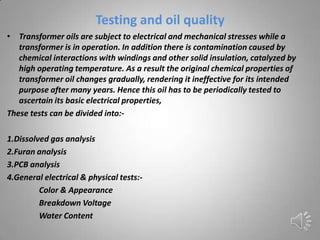
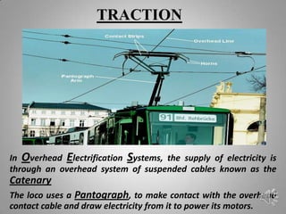
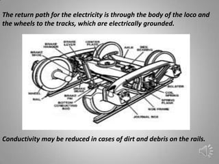
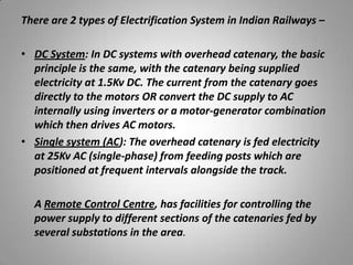
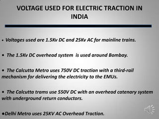
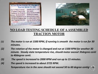
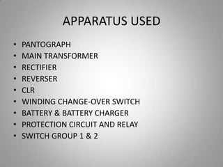
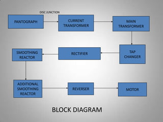
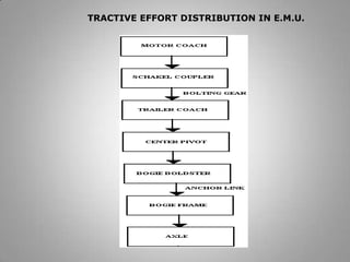
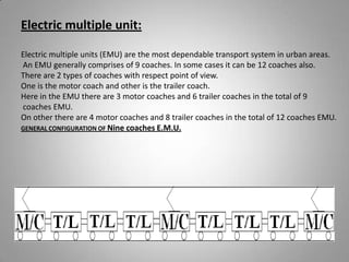
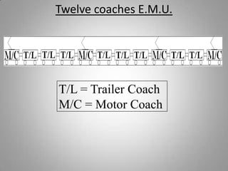
PROJECT REPORT ON VOCATIONAL
          TRAINING
             IN

      INDIAN RAILWAY
ACKNOWLEDGEMENT
We (Subhra Das, Kumar Saurabh, Soutik Das & Uddipan
Halder) students of Camellia Institute of Technology
Digberia(Badu Road, Madhyamgram) would like to pay
our Heart Felt Thanks to the Indian Railway for providing
an Immense knowledge and Cooperation. We would like
to express our Gratitude to Mr A.K.Ghosh.
We are greatful to our Training Guides, Inspiration and
Constructive Suggestion that is helpful for us during the
Training Period.
       1. Mr Debasis Roy (SSE/TSR/SPR)
       2. Mr Alok Chowdhury(SSE/IC/TSR/NKG)
INTRODUCTION
Indian Railway is the world’s fourth largest
commercial, by number of employees with
over 1.4 million employees. Railways were first
introduced in India in 1853. Indian Railways
operates both long distance and suburban rail
systems on a multi-gauge network of board
meter and narrow gauges.
From 20th December 2010, the railways had
developed a 5 digit numbering system. This
need is required because IR runs 10,000 trains
daily.
AT


  SEALDAH STATION


   SSE/E(G)/SDAH-I


(POWER HOUSE AND SUB-
      STATION)
SEALDAH STATION

   At first We went to Sealdah station power
 house, from there we all sent to ‘Dakineshwar
Sub-station’, their We saw feeders that took the
power from CESC and supplied to various colony
                ,pump, pillers, etc.
DAKINESHWAR SUB-STATION
   2 x 25 kV autotransformer system


The 2 x 25 kV autotransformer system may be used on 25 kV lines to reduce
energy losses. It should not be confused with the 50 kV system. The voltage
between the overhead line (3) and the feeder line (5) is 50 kV but the voltage
between the overhead line (3) and the running rails (4) remains at 25 kV and this
is the voltage supplied to the train. This system is used by Indian Railways
FEEDER
The feeders that receives the power from CESC, and the
power is step down with the help of step down
transformer and then supplied to various
colonies, piller box, etc. This process is shown with the
help of above connection diagram.
6kv from CESC goes to HT OCB 400A with the help of HT
busbar 400A is divided into two 200A and sent to two
transformer each of 250 kVA then sent to various parts.
OIL TYPE TRANSFORMER
• Transformer oil or insulating oil is usually a highly-refined mineral oil that is stable at high
temperatures and has excellent electrical insulating properties. It is used in oil-filled
transformers, circuit breakers. Its functions are to insulate, suppress corona and arcing, and
to serve as a coolant.

• The oil helps cool the transformer. Because it also provides part of the electrical insulation
between internal live parts, transformer oil must remain stable at high temperatures for an
extended period. To improve cooling of large power transformers, the oil-filled tank may
have external radiators through which the oil circulates by natural convection.

• The flash point (min) and pour point (max) are 140 °C and −6 °C respectively. The
dielectric strength of new untreated oil is 12 MV/m (RMS) and after treatment it should be
>24 MV/m (RMS).
Testing and oil quality
• Transformer oils are subject to electrical and mechanical stresses while a
   transformer is in operation. In addition there is contamination caused by
   chemical interactions with windings and other solid insulation, catalyzed by
   high operating temperature. As a result the original chemical properties of
   transformer oil changes gradually, rendering it ineffective for its intended
   purpose after many years. Hence this oil has to be periodically tested to
   ascertain its basic electrical properties,
These tests can be divided into:-

1.Dissolved gas analysis
2.Furan analysis
3.PCB analysis
4.General electrical & physical tests:-
         Color & Appearance
         Breakdown Voltage
         Water Content
AT
BARASAT CARSHED
   SSE/TRS/BT
TRACTION


In Overhead Electrification Systems, the supply of electricity is
through an overhead system of suspended cables known as the
Catenary
The loco uses a Pantograph, to make contact with the overhead
contact cable and draw electricity from it to power its motors.
The return path for the electricity is through the body of the loco and
the wheels to the tracks, which are electrically grounded.


Conductivity may be reduced in cases of dirt and debris on the rails.
There are 2 types of Electrification System in Indian Railways –

• DC System: In DC systems with overhead catenary, the basic
  principle is the same, with the catenary being supplied
  electricity at 1.5Kv DC. The current from the catenary goes
  directly to the motors OR convert the DC supply to AC
  internally using inverters or a motor-generator combination
  which then drives AC motors.
• Single system (AC): The overhead catenary is fed electricity
  at 25Kv AC (single-phase) from feeding posts which are
  positioned at frequent intervals alongside the track.

  A Remote Control Centre, has facilities for controlling the
  power supply to different sections of the catenaries fed by
  several substations in the area.
VOLTAGE USED FOR ELECTRIC TRACTION IN
                        INDIA


•   Voltages used are 1.5Kv DC and 25Kv AC for mainline trains.

• The 1.5Kv DC overhead system is used around Bombay.

• The Calcutta Metro uses 750V DC traction with a third-rail
mechanism for delivering the electricity to the EMUs.

• The Calcutta trams use 550V DC with an overhead catenary system
with underground return conductors.

●Delhi Metro uses 25KV AC Overhead Traction.
NO LOAD TESTING SCHEDULE OF A ASSEMBLED
                  TRACTION MOTOR

(1)   The motor is run at 1500 RPM, if running is smooth the motor is run for 30
      minutes.
(2)   The rotation of the motor is changed and run at 1500 RPM for another 30
      minute. Steady state temperature rise, should motor exceed 35degree centi
      to 40degree centi.
(3)    The speed is increased to 2000 RPM and run up to 15 minutes.
(4)   The speed is increased to about 2725 RPM.
      Temperature rise in the zone should not exceed 50 to 60 degree centigrade.
AT

NARKELDANGA CARSHED

    SSE/TRS/NKG
APPARATUS USED
•   PANTOGRAPH
•   MAIN TRANSFORMER
•   RECTIFIER
•   REVERSER
•   CLR
•   WINDING CHANGE-OVER SWITCH
•   BATTERY & BATTERY CHARGER
•   PROTECTION CIRCUIT AND RELAY
•   SWITCH GROUP 1 & 2
DISC JUNCTION


PANTOGRAPH                      CURRENT          MAIN
                              TRANSFORMER    TRANSFORMER


SMOOTHING                        RECTIFIER       TAP
 REACTOR                                       CHANGER


 ADDITIONAL
 SMOOTHING                       REVERSER       MOTOR
  REACTOR


                      BLOCK DIAGRAM
TRACTIVE EFFORT DISTRIBUTION IN E.M.U.
Electric multiple unit:

Electric multiple units (EMU) are the most dependable transport system in urban areas.
An EMU generally comprises of 9 coaches. In some cases it can be 12 coaches also.
There are 2 types of coaches with respect point of view.
One is the motor coach and other is the trailer coach.
Here in the EMU there are 3 motor coaches and 6 trailer coaches in the total of 9
coaches EMU.
On other there are 4 motor coaches and 8 trailer coaches in the total of 12 coaches EMU.
GENERAL CONFIGURATION OF Nine coaches E.M.U.
Twelve coaches E.M.U.


T/L = Trailer Coach
M/C = Motor Coach
Presented by –

  1.   Subhra Das
  2.   Kumar Saurabh
  3.   Soutik Das
  4.   Uddipan Halder

Railway training

  • 1.
    PROJECT REPORT ONVOCATIONAL TRAINING IN INDIAN RAILWAY
  • 2.
    ACKNOWLEDGEMENT We (Subhra Das,Kumar Saurabh, Soutik Das & Uddipan Halder) students of Camellia Institute of Technology Digberia(Badu Road, Madhyamgram) would like to pay our Heart Felt Thanks to the Indian Railway for providing an Immense knowledge and Cooperation. We would like to express our Gratitude to Mr A.K.Ghosh. We are greatful to our Training Guides, Inspiration and Constructive Suggestion that is helpful for us during the Training Period. 1. Mr Debasis Roy (SSE/TSR/SPR) 2. Mr Alok Chowdhury(SSE/IC/TSR/NKG)
  • 3.
    INTRODUCTION Indian Railway isthe world’s fourth largest commercial, by number of employees with over 1.4 million employees. Railways were first introduced in India in 1853. Indian Railways operates both long distance and suburban rail systems on a multi-gauge network of board meter and narrow gauges. From 20th December 2010, the railways had developed a 5 digit numbering system. This need is required because IR runs 10,000 trains daily.
  • 4.
    AT SEALDAHSTATION SSE/E(G)/SDAH-I (POWER HOUSE AND SUB- STATION)
  • 5.
    SEALDAH STATION At first We went to Sealdah station power house, from there we all sent to ‘Dakineshwar Sub-station’, their We saw feeders that took the power from CESC and supplied to various colony ,pump, pillers, etc.
  • 6.
    DAKINESHWAR SUB-STATION 2 x 25 kV autotransformer system The 2 x 25 kV autotransformer system may be used on 25 kV lines to reduce energy losses. It should not be confused with the 50 kV system. The voltage between the overhead line (3) and the feeder line (5) is 50 kV but the voltage between the overhead line (3) and the running rails (4) remains at 25 kV and this is the voltage supplied to the train. This system is used by Indian Railways
  • 7.
    FEEDER The feeders thatreceives the power from CESC, and the power is step down with the help of step down transformer and then supplied to various colonies, piller box, etc. This process is shown with the help of above connection diagram. 6kv from CESC goes to HT OCB 400A with the help of HT busbar 400A is divided into two 200A and sent to two transformer each of 250 kVA then sent to various parts.
  • 8.
    OIL TYPE TRANSFORMER •Transformer oil or insulating oil is usually a highly-refined mineral oil that is stable at high temperatures and has excellent electrical insulating properties. It is used in oil-filled transformers, circuit breakers. Its functions are to insulate, suppress corona and arcing, and to serve as a coolant. • The oil helps cool the transformer. Because it also provides part of the electrical insulation between internal live parts, transformer oil must remain stable at high temperatures for an extended period. To improve cooling of large power transformers, the oil-filled tank may have external radiators through which the oil circulates by natural convection. • The flash point (min) and pour point (max) are 140 °C and −6 °C respectively. The dielectric strength of new untreated oil is 12 MV/m (RMS) and after treatment it should be >24 MV/m (RMS).
  • 9.
    Testing and oilquality • Transformer oils are subject to electrical and mechanical stresses while a transformer is in operation. In addition there is contamination caused by chemical interactions with windings and other solid insulation, catalyzed by high operating temperature. As a result the original chemical properties of transformer oil changes gradually, rendering it ineffective for its intended purpose after many years. Hence this oil has to be periodically tested to ascertain its basic electrical properties, These tests can be divided into:- 1.Dissolved gas analysis 2.Furan analysis 3.PCB analysis 4.General electrical & physical tests:- Color & Appearance Breakdown Voltage Water Content
  • 10.
  • 11.
    TRACTION In Overhead ElectrificationSystems, the supply of electricity is through an overhead system of suspended cables known as the Catenary The loco uses a Pantograph, to make contact with the overhead contact cable and draw electricity from it to power its motors.
  • 12.
    The return pathfor the electricity is through the body of the loco and the wheels to the tracks, which are electrically grounded. Conductivity may be reduced in cases of dirt and debris on the rails.
  • 13.
    There are 2types of Electrification System in Indian Railways – • DC System: In DC systems with overhead catenary, the basic principle is the same, with the catenary being supplied electricity at 1.5Kv DC. The current from the catenary goes directly to the motors OR convert the DC supply to AC internally using inverters or a motor-generator combination which then drives AC motors. • Single system (AC): The overhead catenary is fed electricity at 25Kv AC (single-phase) from feeding posts which are positioned at frequent intervals alongside the track. A Remote Control Centre, has facilities for controlling the power supply to different sections of the catenaries fed by several substations in the area.
  • 14.
    VOLTAGE USED FORELECTRIC TRACTION IN INDIA • Voltages used are 1.5Kv DC and 25Kv AC for mainline trains. • The 1.5Kv DC overhead system is used around Bombay. • The Calcutta Metro uses 750V DC traction with a third-rail mechanism for delivering the electricity to the EMUs. • The Calcutta trams use 550V DC with an overhead catenary system with underground return conductors. ●Delhi Metro uses 25KV AC Overhead Traction.
  • 15.
    NO LOAD TESTINGSCHEDULE OF A ASSEMBLED TRACTION MOTOR (1) The motor is run at 1500 RPM, if running is smooth the motor is run for 30 minutes. (2) The rotation of the motor is changed and run at 1500 RPM for another 30 minute. Steady state temperature rise, should motor exceed 35degree centi to 40degree centi. (3) The speed is increased to 2000 RPM and run up to 15 minutes. (4) The speed is increased to about 2725 RPM. Temperature rise in the zone should not exceed 50 to 60 degree centigrade.
  • 16.
  • 17.
    APPARATUS USED • PANTOGRAPH • MAIN TRANSFORMER • RECTIFIER • REVERSER • CLR • WINDING CHANGE-OVER SWITCH • BATTERY & BATTERY CHARGER • PROTECTION CIRCUIT AND RELAY • SWITCH GROUP 1 & 2
  • 18.
    DISC JUNCTION PANTOGRAPH CURRENT MAIN TRANSFORMER TRANSFORMER SMOOTHING RECTIFIER TAP REACTOR CHANGER ADDITIONAL SMOOTHING REVERSER MOTOR REACTOR BLOCK DIAGRAM
  • 19.
  • 20.
    Electric multiple unit: Electricmultiple units (EMU) are the most dependable transport system in urban areas. An EMU generally comprises of 9 coaches. In some cases it can be 12 coaches also. There are 2 types of coaches with respect point of view. One is the motor coach and other is the trailer coach. Here in the EMU there are 3 motor coaches and 6 trailer coaches in the total of 9 coaches EMU. On other there are 4 motor coaches and 8 trailer coaches in the total of 12 coaches EMU. GENERAL CONFIGURATION OF Nine coaches E.M.U.
  • 21.
    Twelve coaches E.M.U. T/L= Trailer Coach M/C = Motor Coach
  • 22.
    Presented by – 1. Subhra Das 2. Kumar Saurabh 3. Soutik Das 4. Uddipan Halder