Download as PDF, PPTX

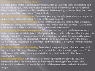
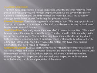
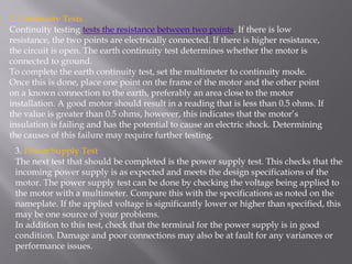
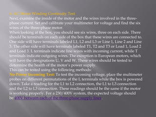
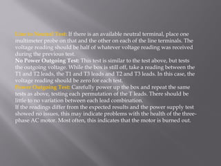

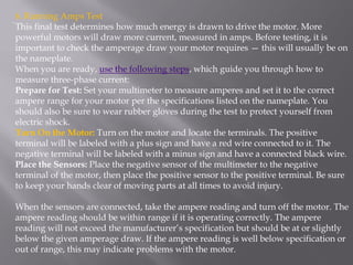

The document provides procedures for testing a 3-phase motor that is exhibiting problems. It describes safety precautions and 6 types of tests: 1) general inspection, 2) continuity tests, 3) power supply test, 4) AC motor winding continuity test, 5) insulation resistance test, and 6) running amps test. The tests check for visual damage, grounding integrity, proper voltage levels, winding connections and insulation, and current draw compared to specifications. Identifying failures in these areas can help diagnose motor issues.


![[IJET V2I3P12] Authors: France O. Akpojedje, Ese M. Okah, and Yussuf O. Abu](https://cdn.slidesharecdn.com/ss_thumbnails/ijet-v2i3p12-160609053434-thumbnail.jpg?width=640&height=640&fit=bounds)


