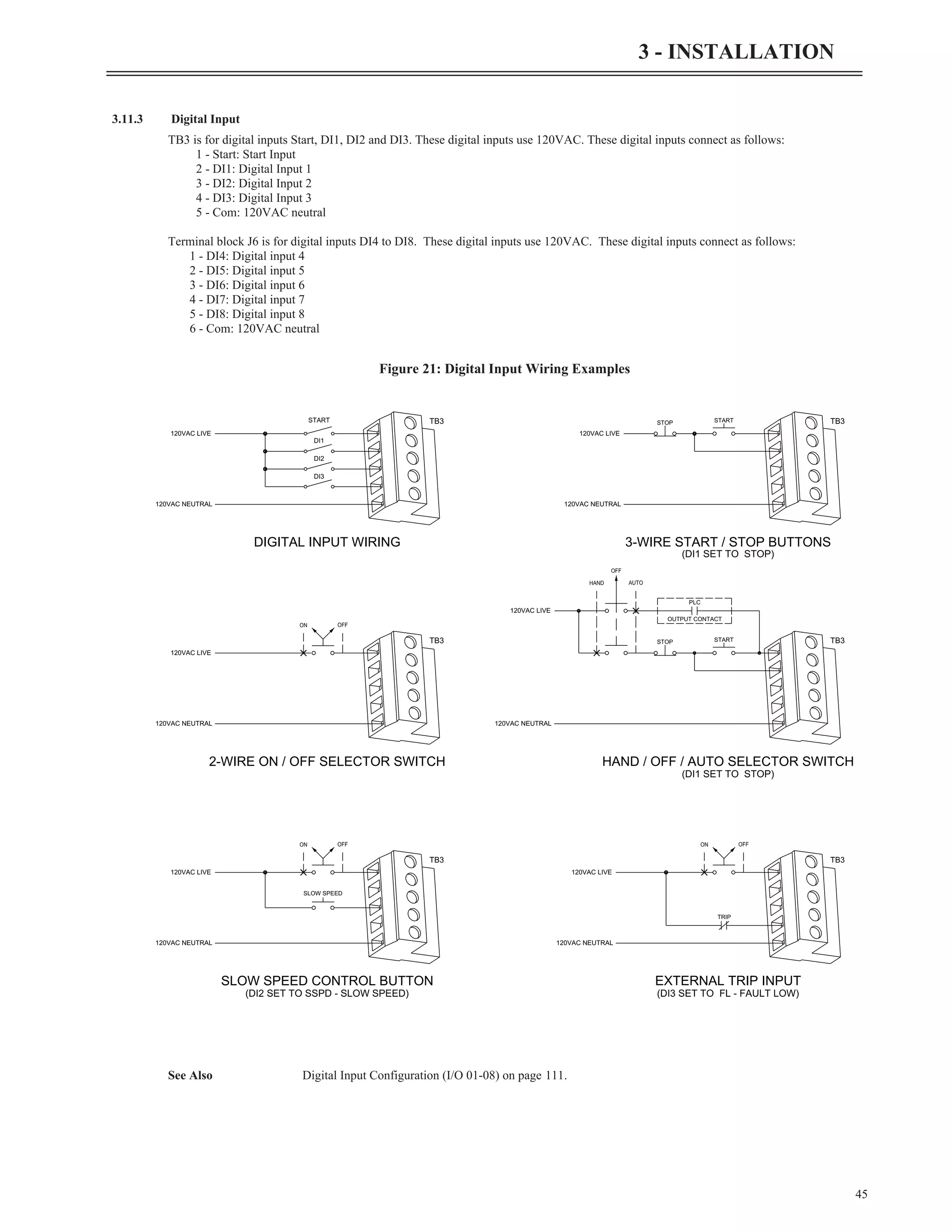
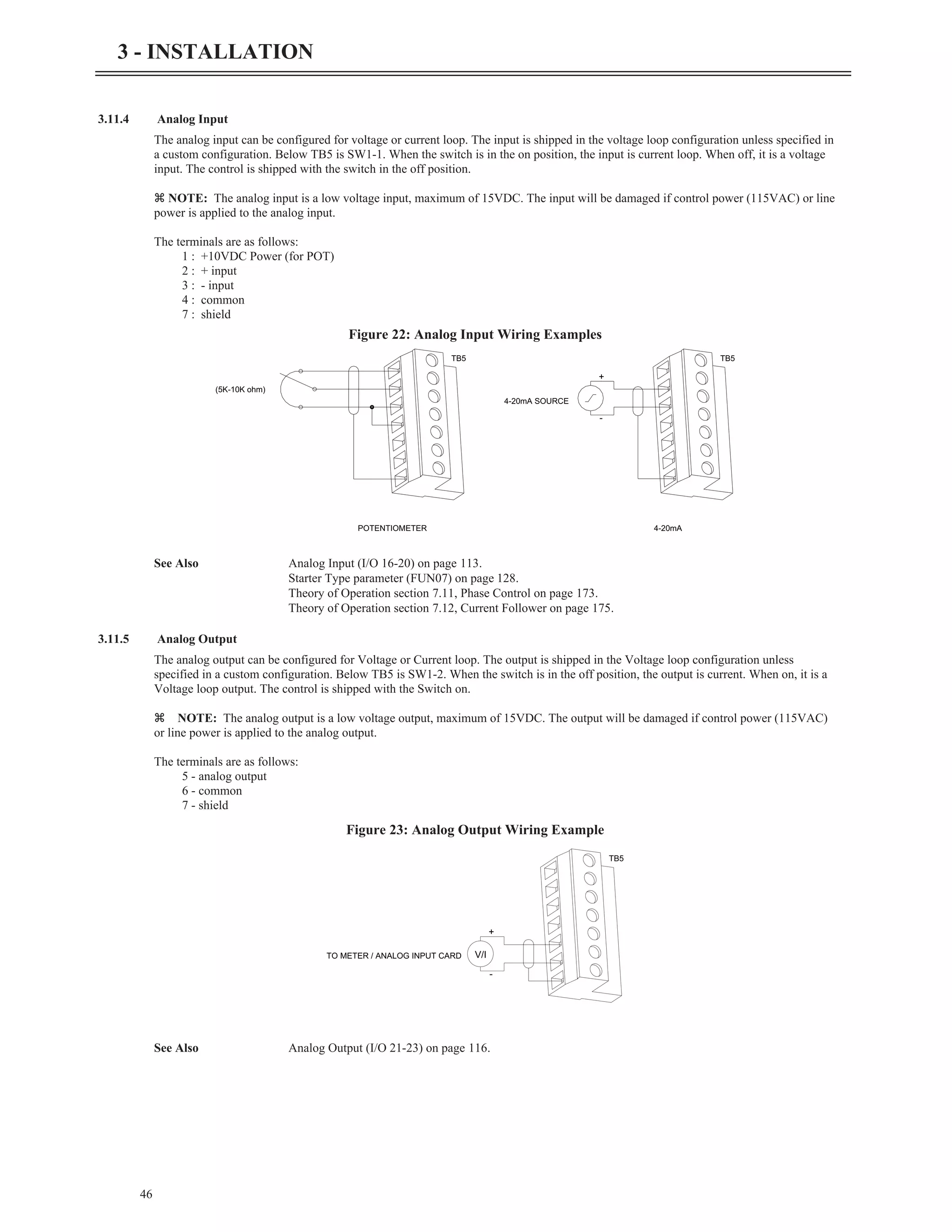
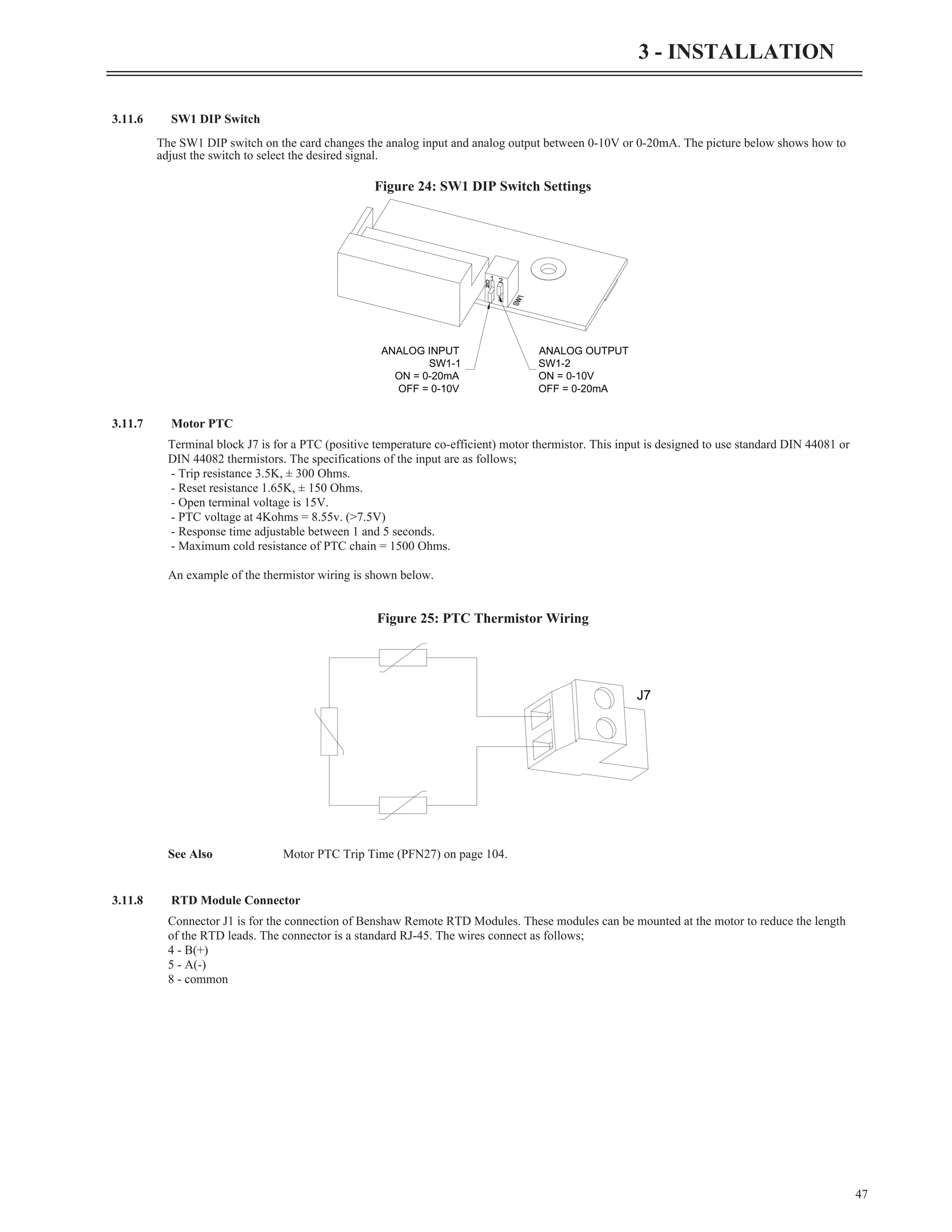
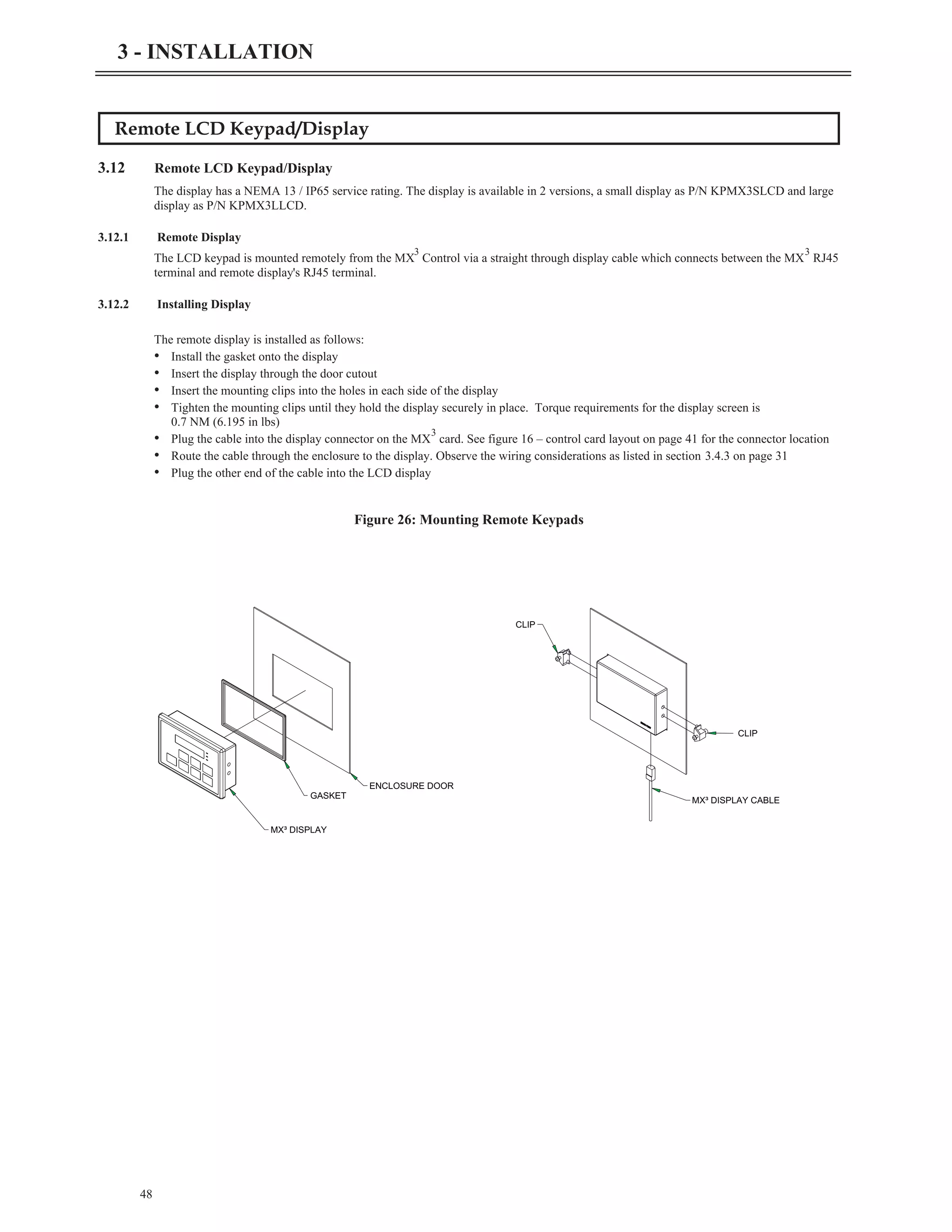
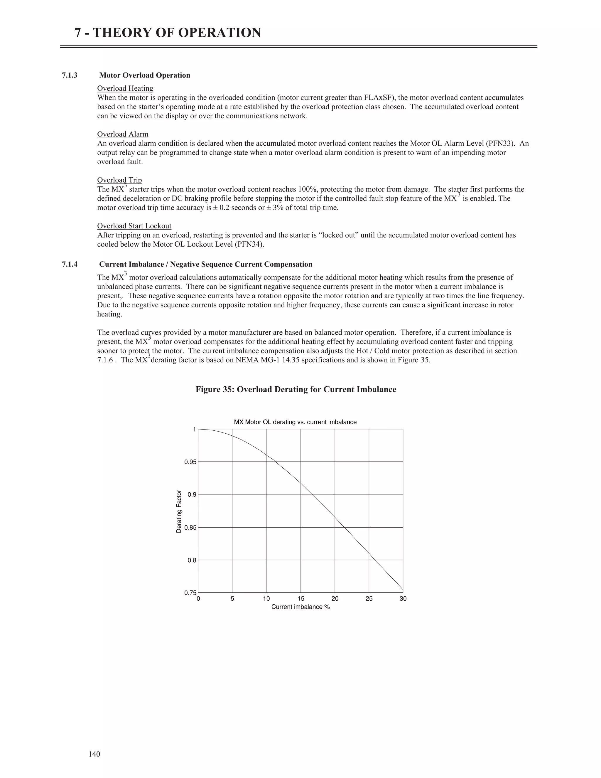
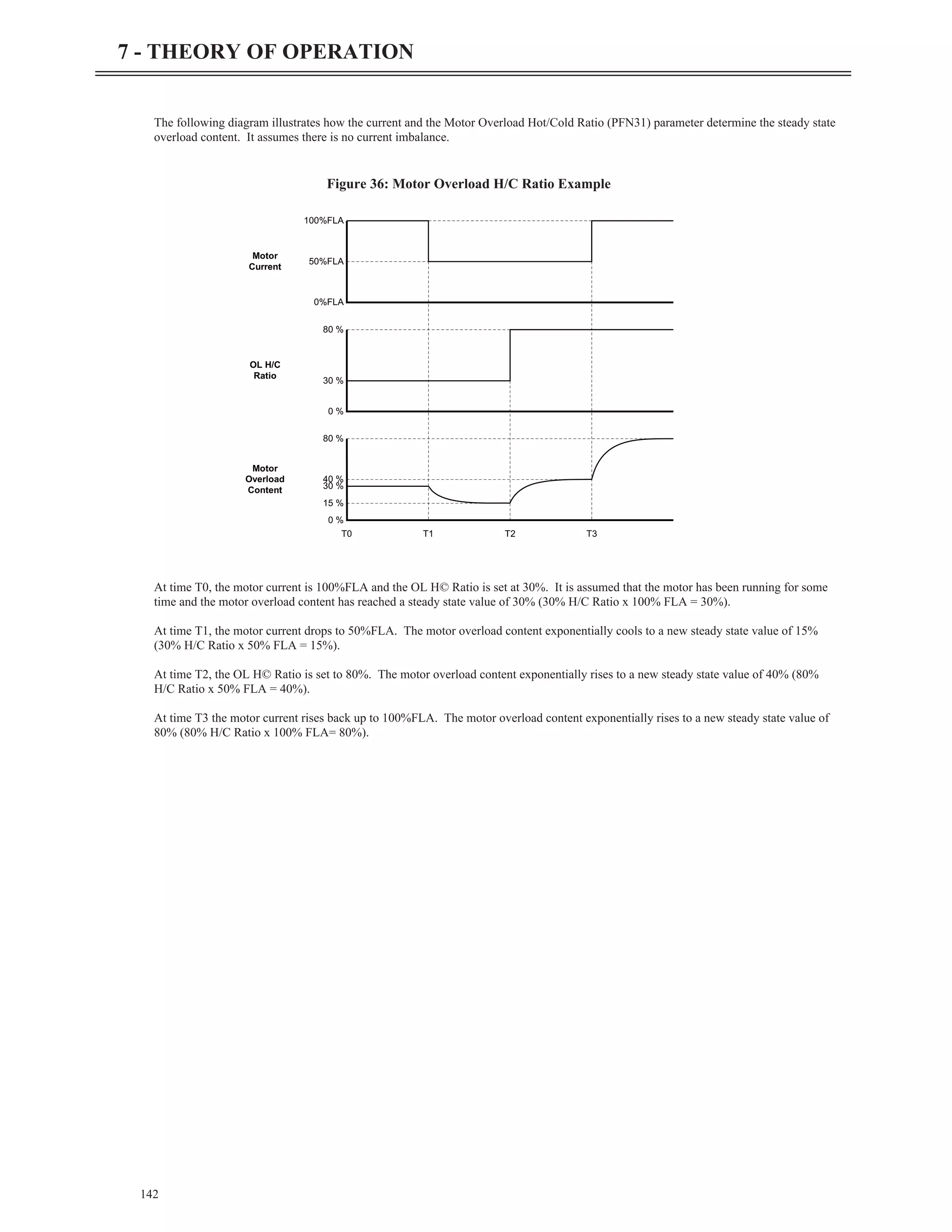
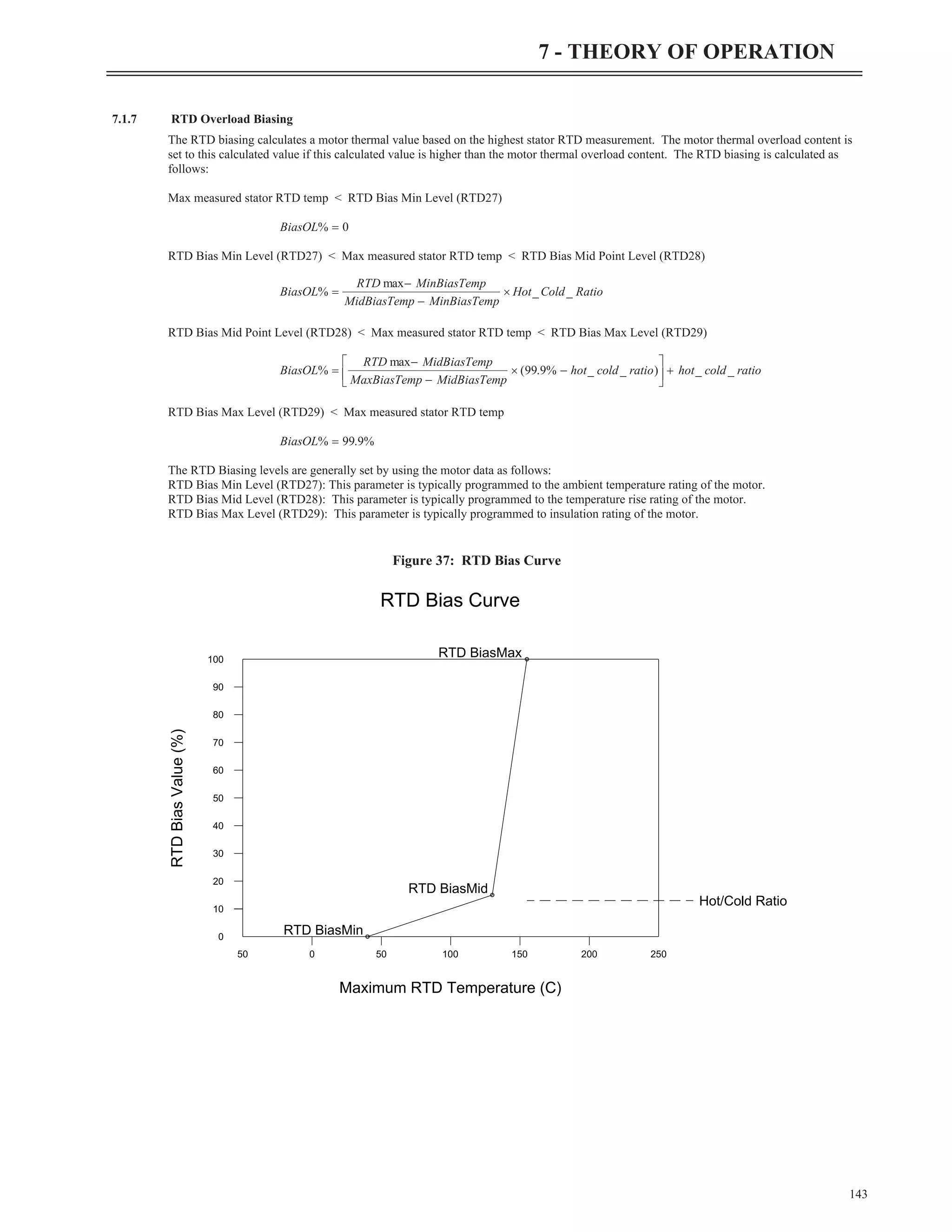
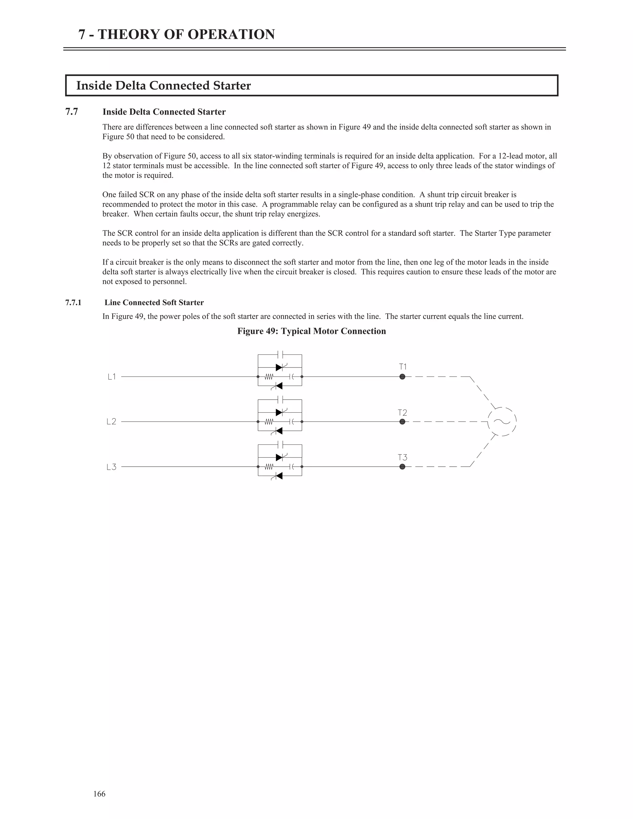
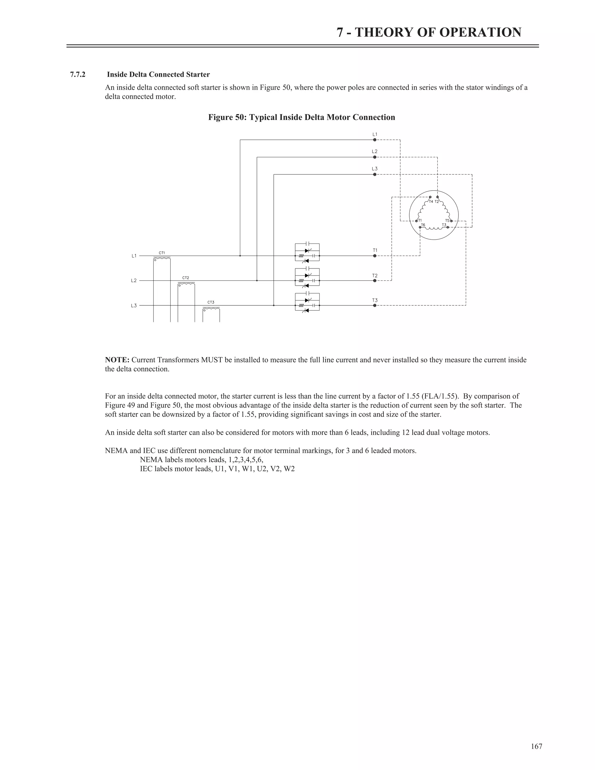
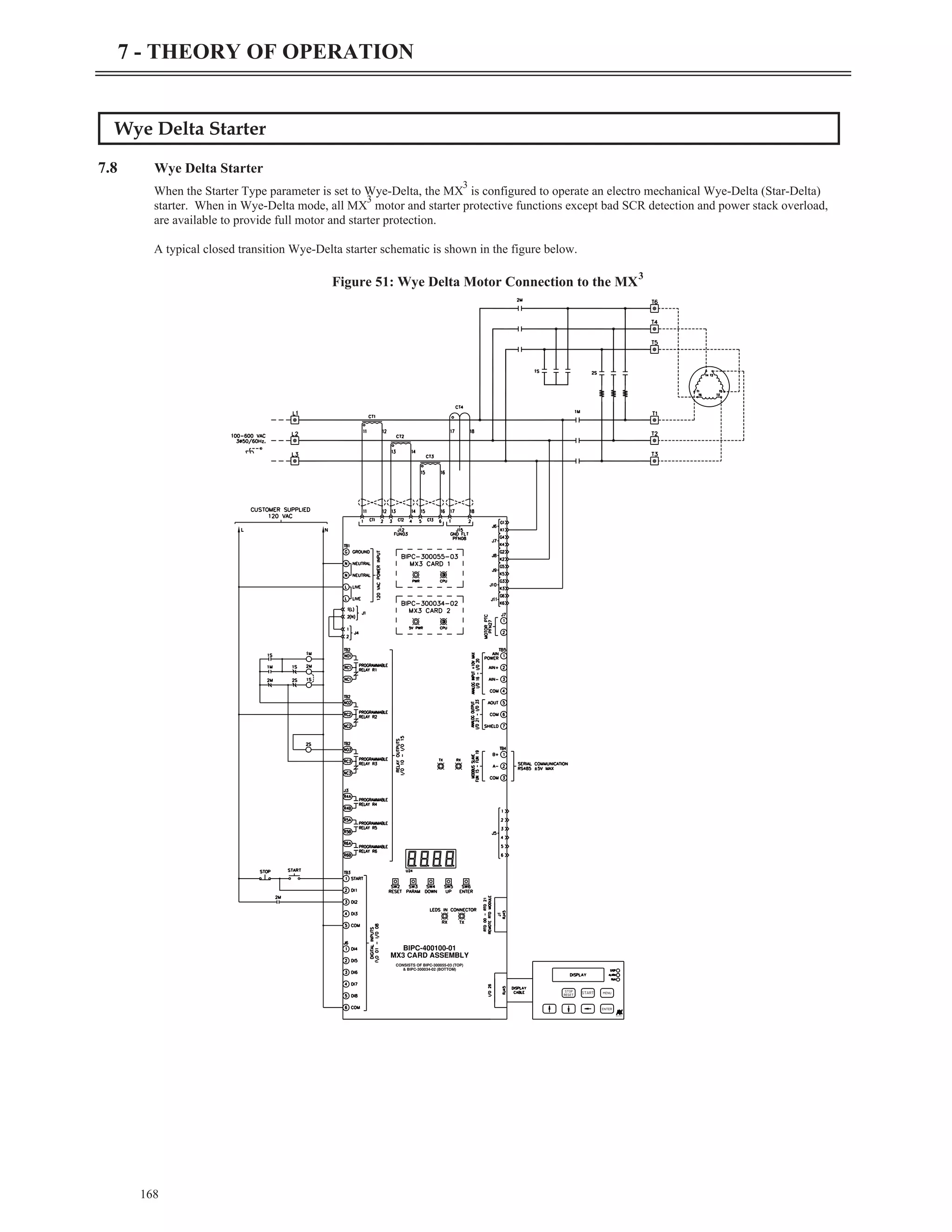
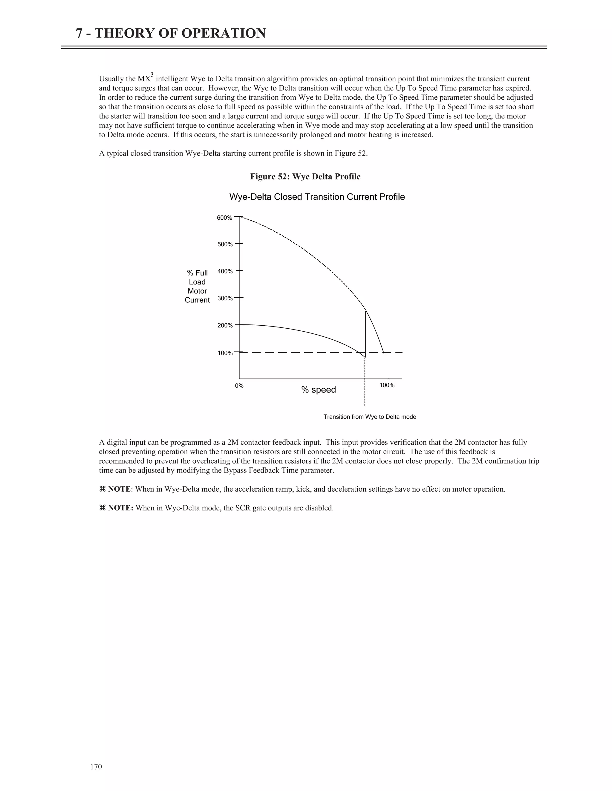
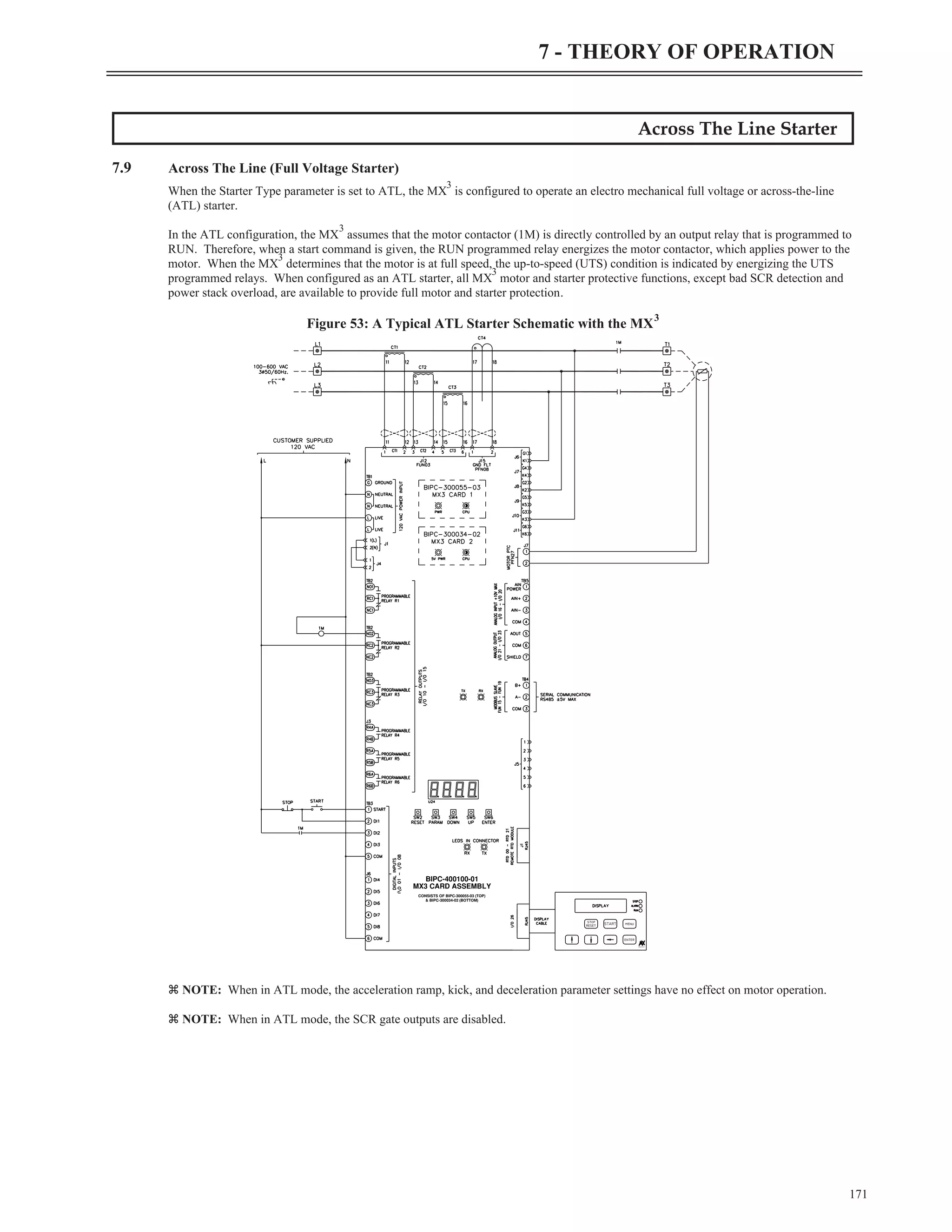
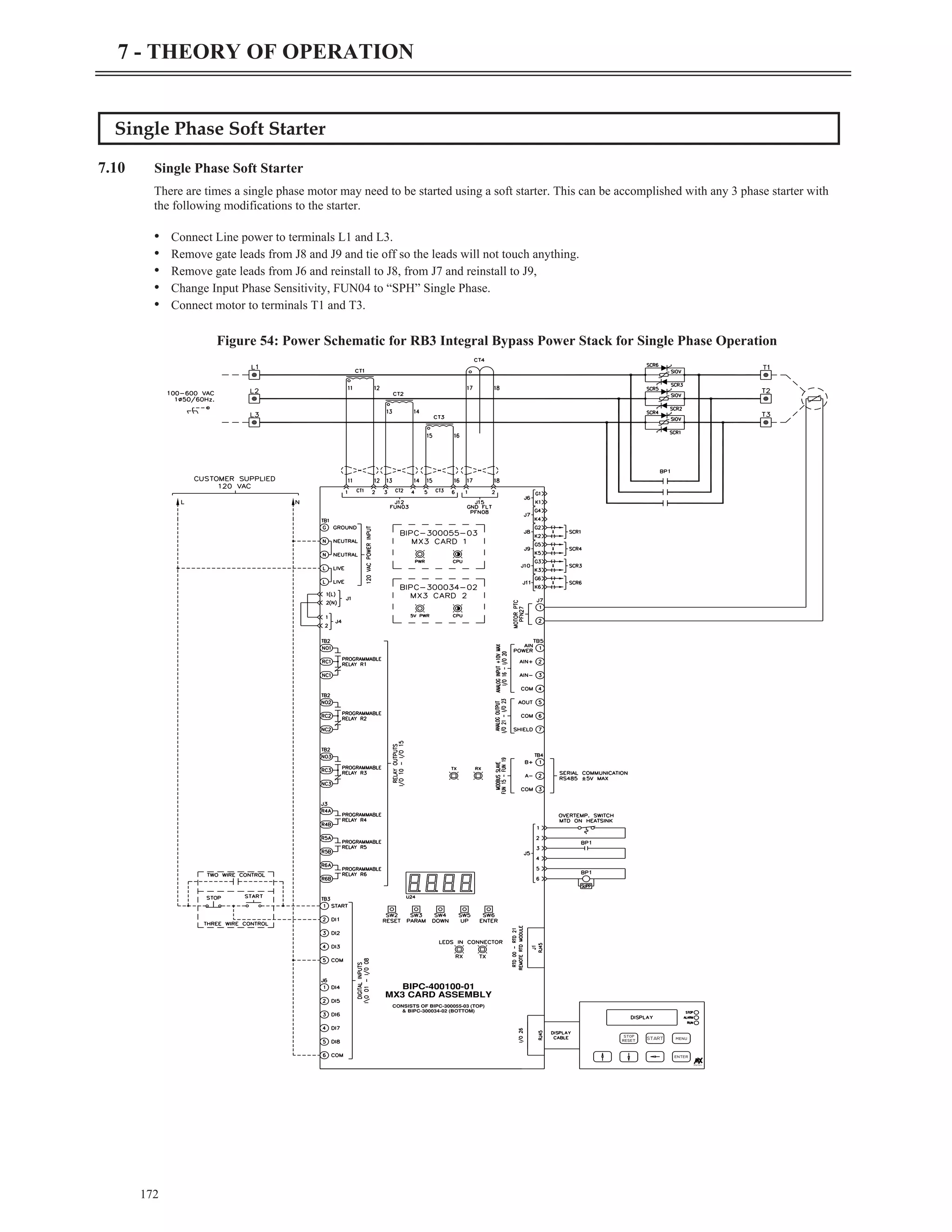
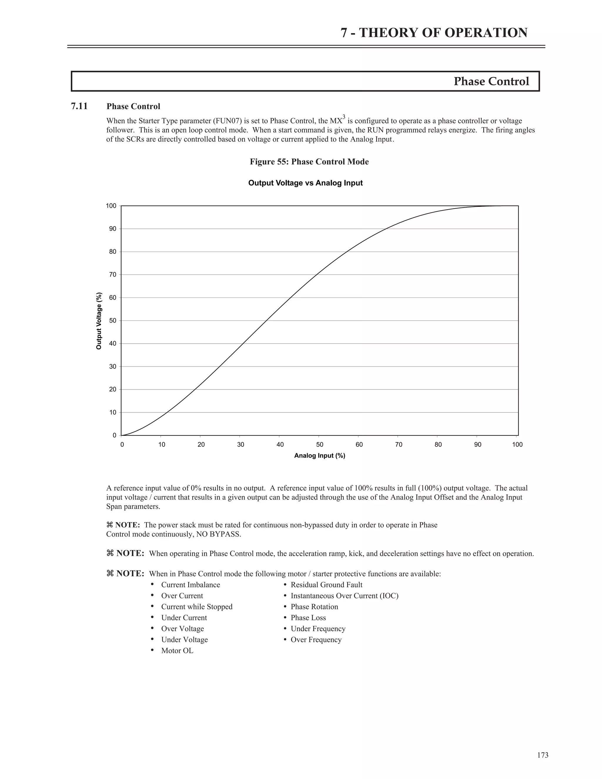
This document is a user manual for Benshaw's RediStart MX3 Solid State Starter control systems. It begins with safety and legal notices, then provides specifications and technical details on the starter components and their electrical ratings. The bulk of the document covers installation instructions, including considerations for site preparation, mounting, wiring practices, and power and control wiring diagrams. It provides guidance on proper installation to ensure safe and effective operation of the starter system.


![Environmental Conditions
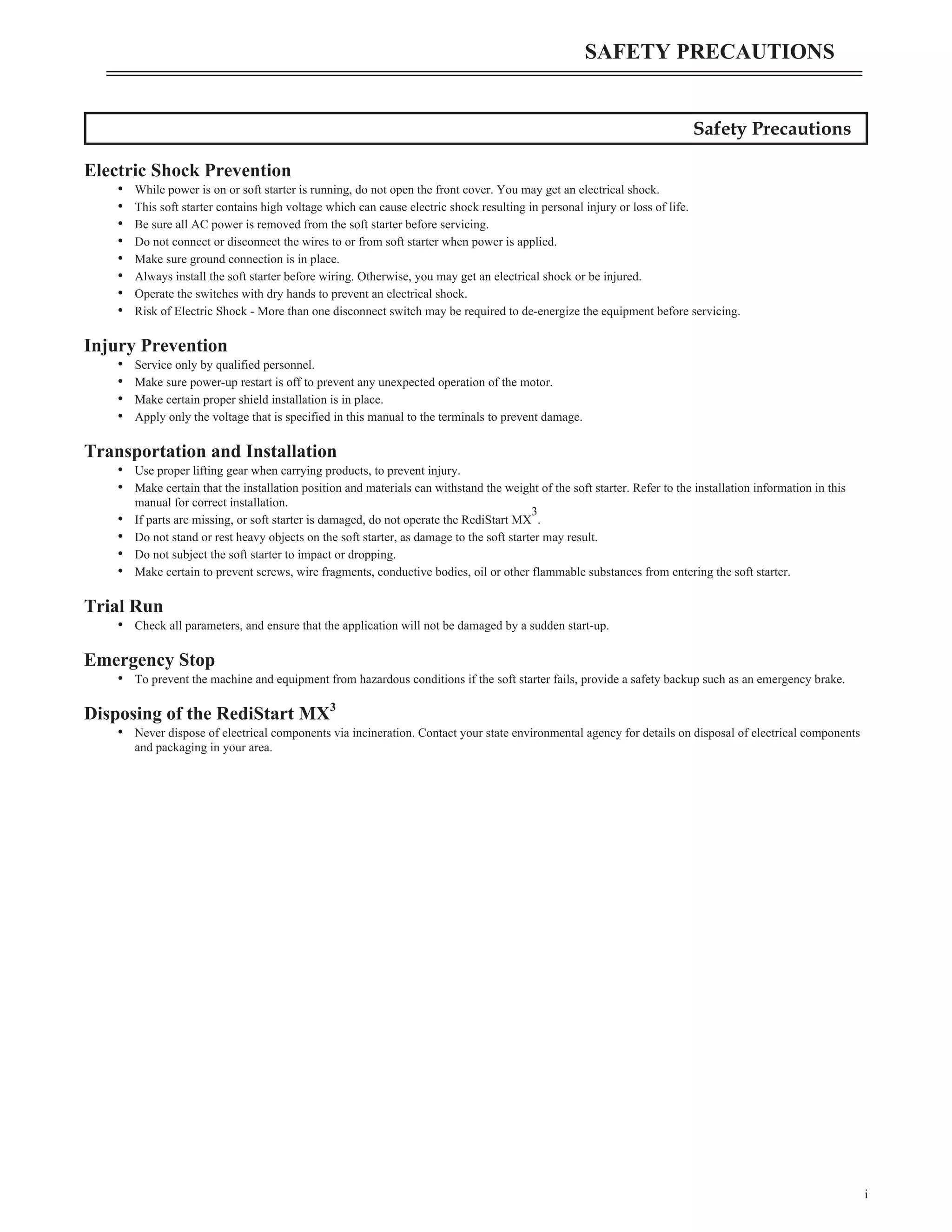
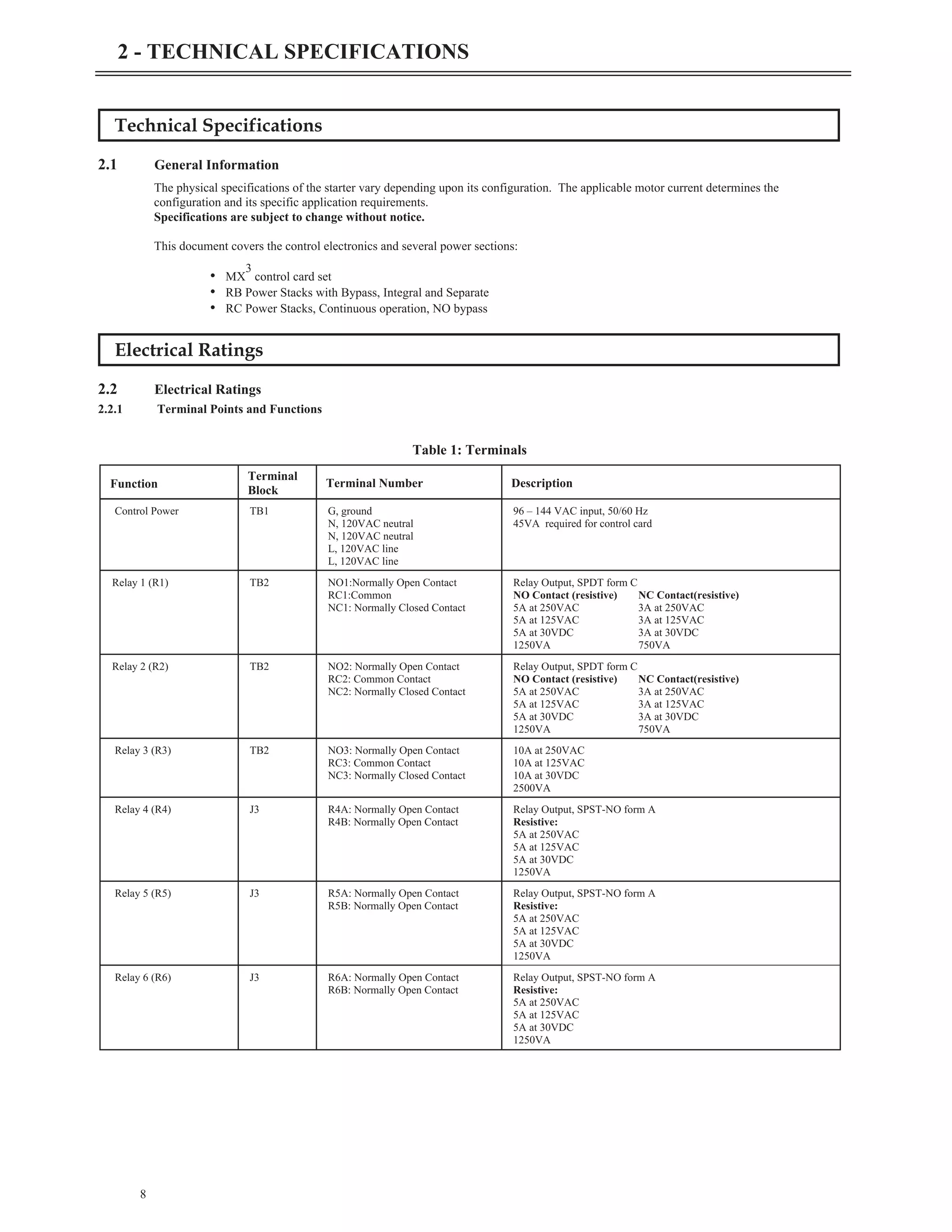
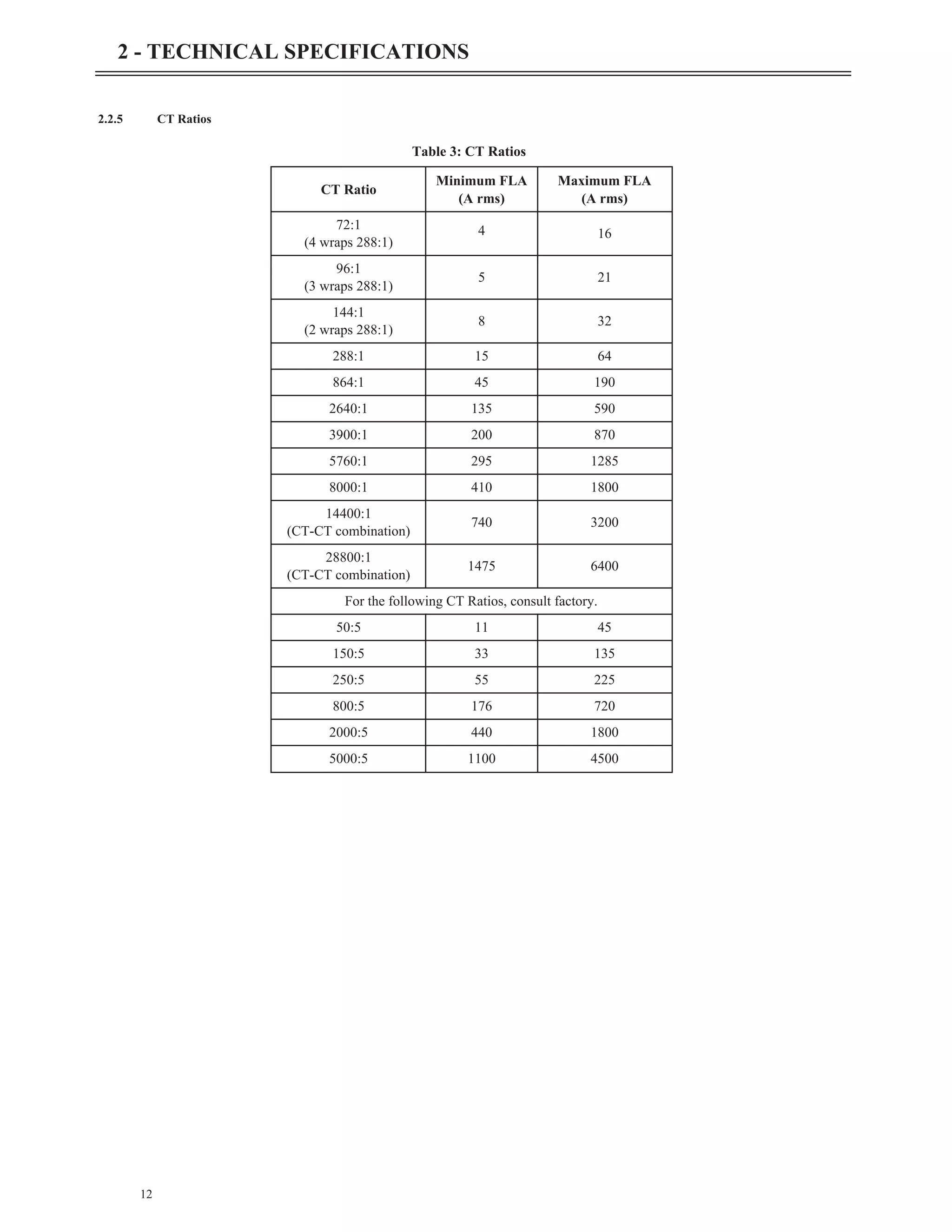
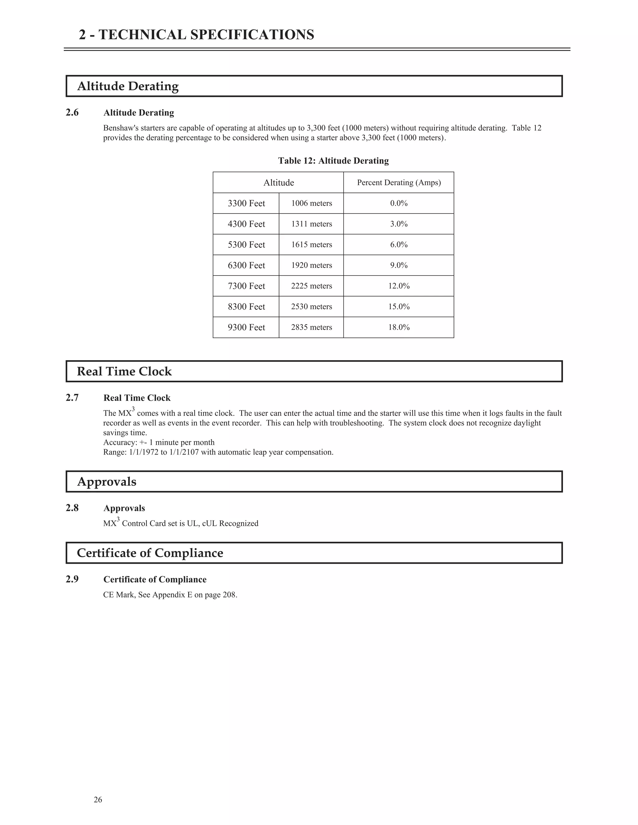
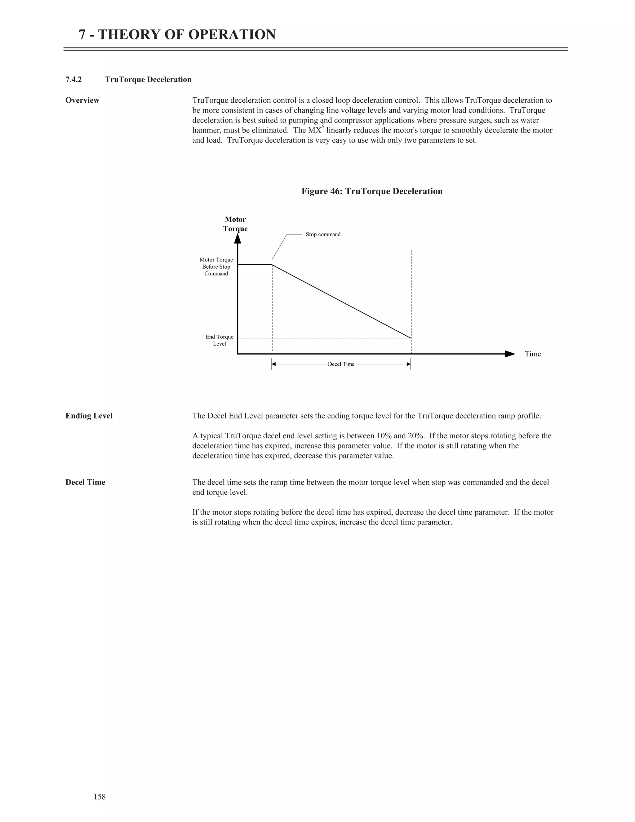
2.5 Environmental Conditions
25
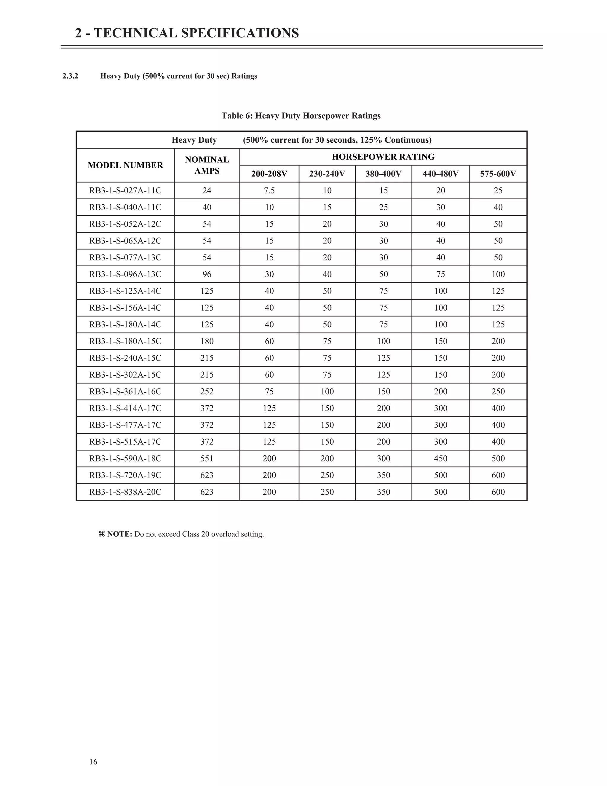
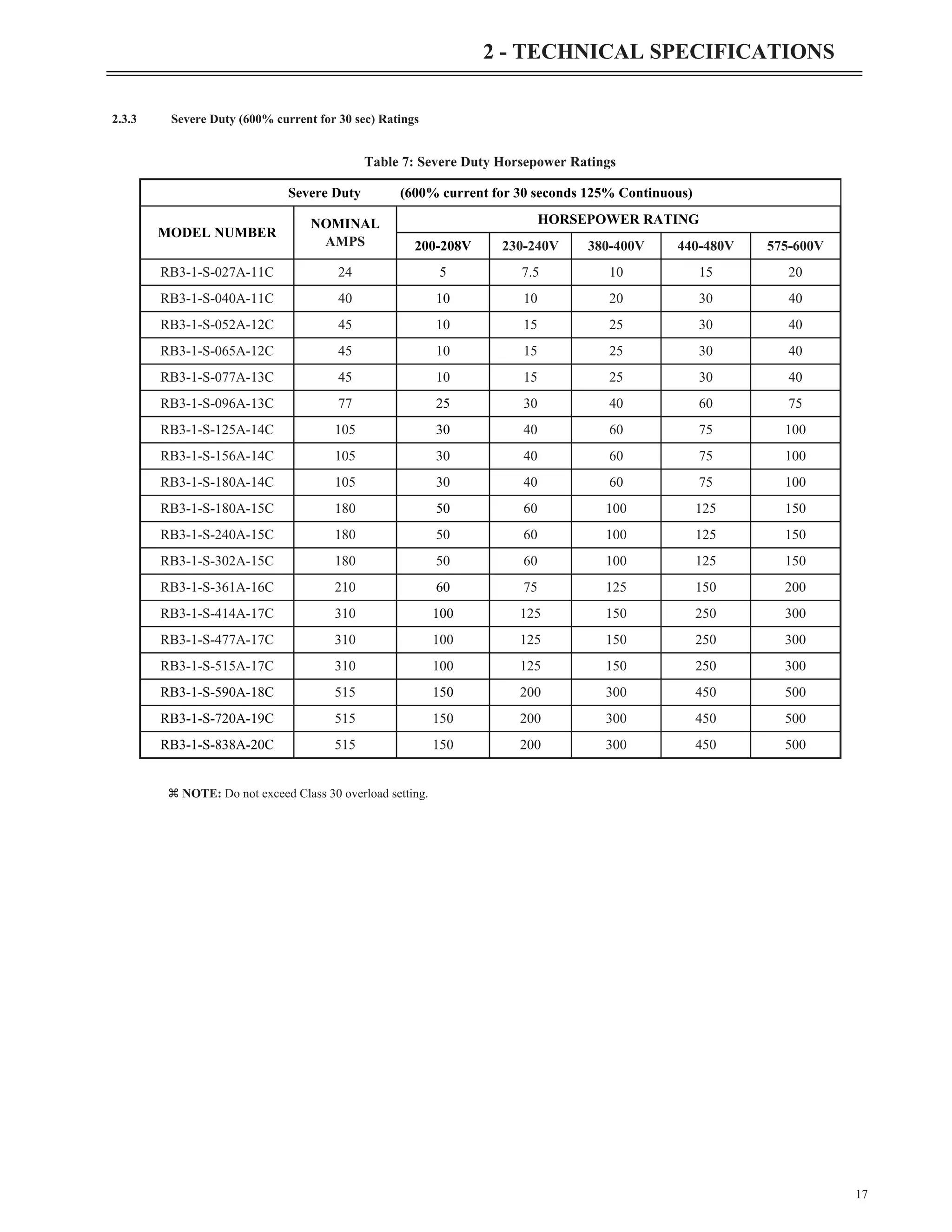
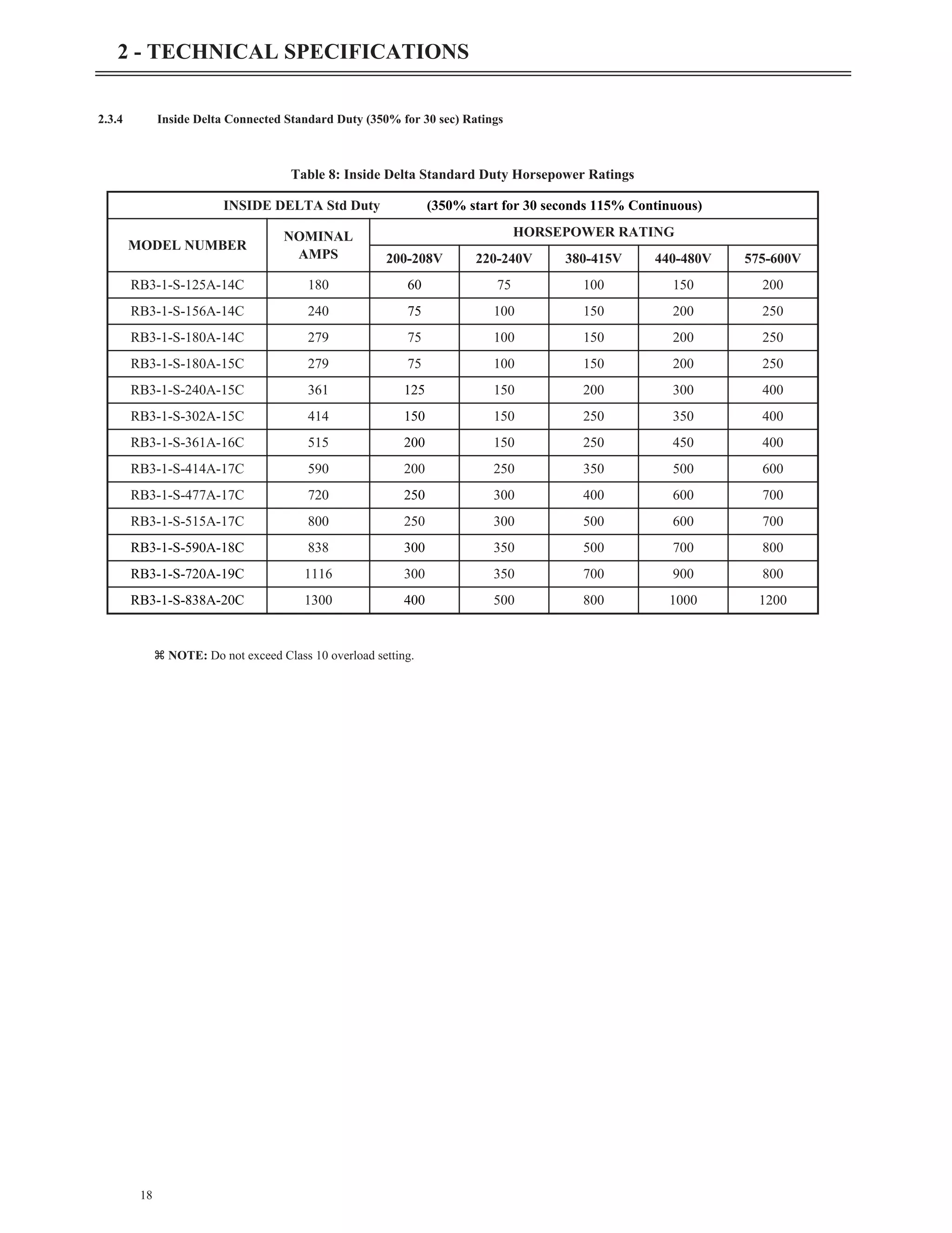
2 - TECHNICAL SPECIFICATIONS
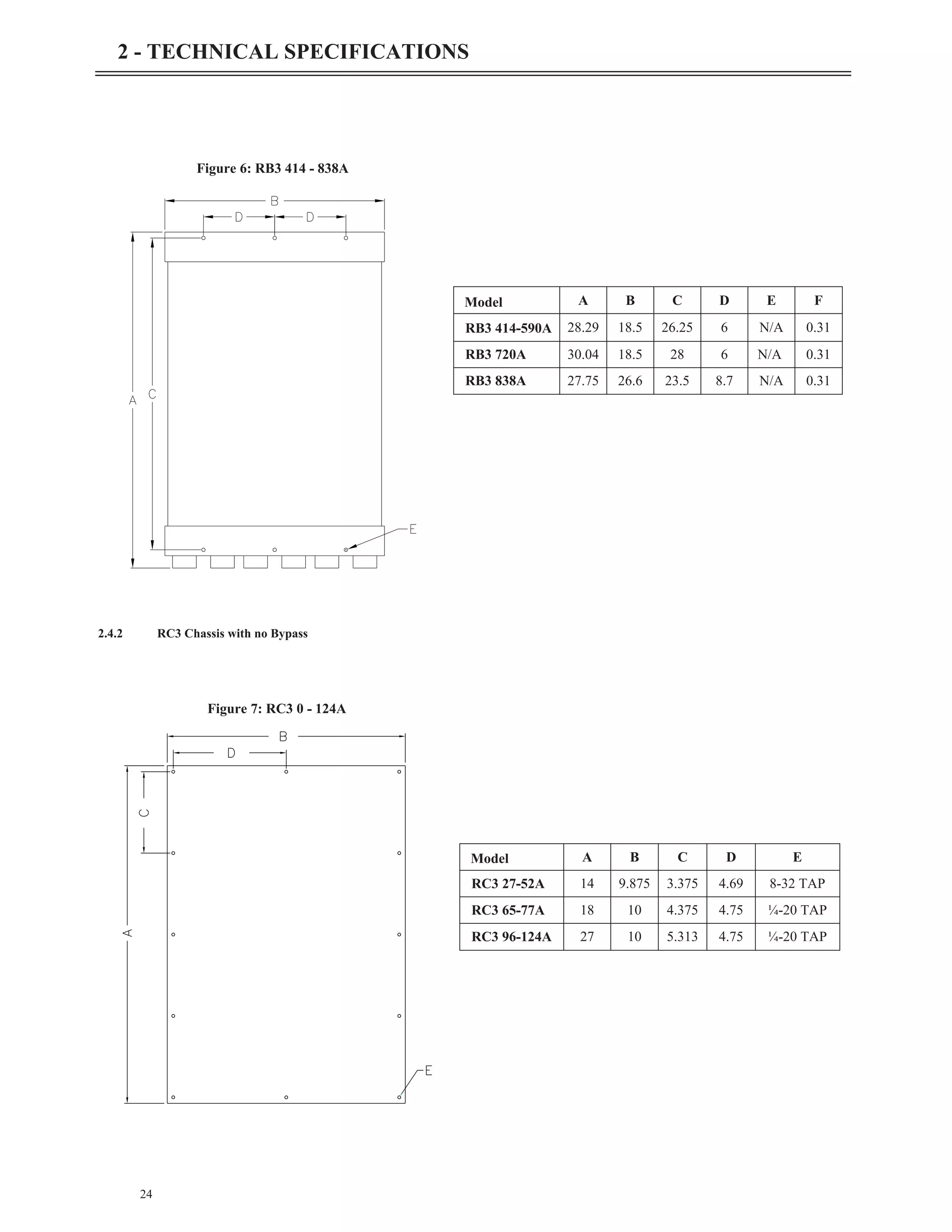
Model A B C D E
RC3 156-180A 18 15 17 13.5 0.3
RC3 240A 24 15 23 13.5 0.5
RC3 302-361A 28 17.25 27 15.75 0.5
RC3 477A 28 20 27 18.5 0.5
RC3 590A 35 20 34 18.5 0.5
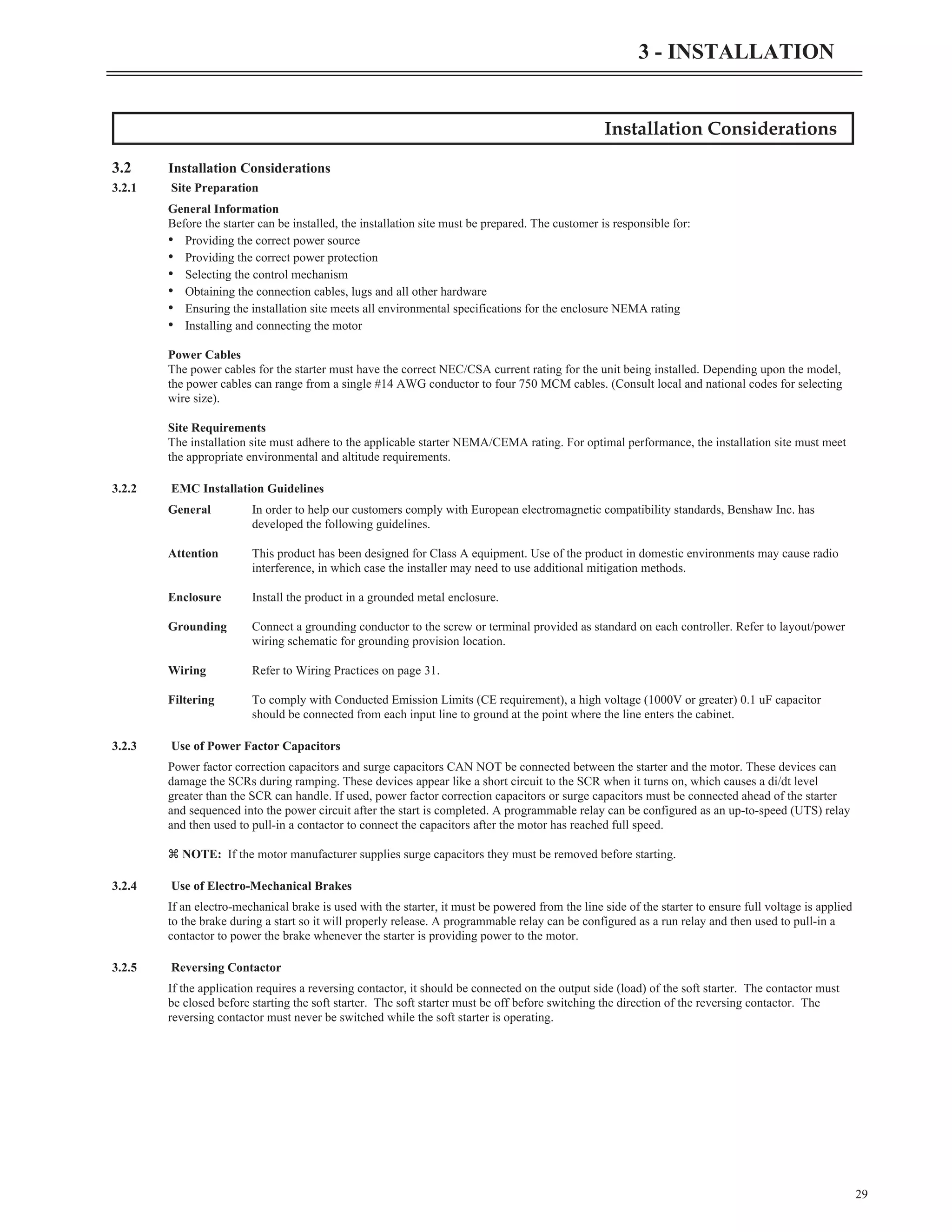
Operating Temperatures
-10°C to +40°C (14°F to 104°F)enclosed
-10°C to +50°C (14°F to 122°F)open
Storage Temperatures -20°C to +70°C (-4°F to 155°F)
Humidity 0% to 95% non condensing
Altitude 1000m (3300ft) without derating
Maximum Vibration 5.9m/s2
(19.2ft/s2
) [0.6G]
Cooling
RC (Natural convection)
RB (Bypassed)
Table 11: Environmental Ratings
Figure 8: RC3 156 - 590A](https://image.slidesharecdn.com/01-890034-02-00-lv-mx3-user-manual-1-210614135928/75/01-890034-02-00-lv-mx3-user-manual-1-33-2048.jpg)
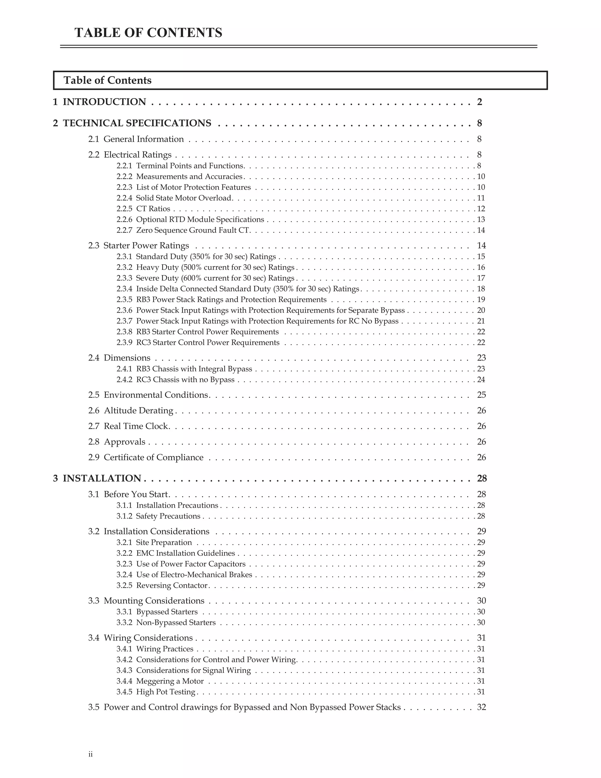
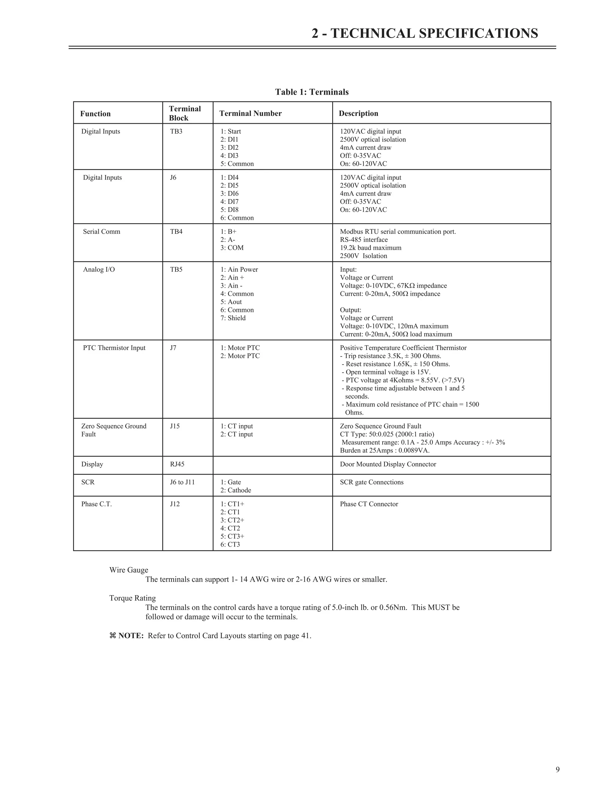
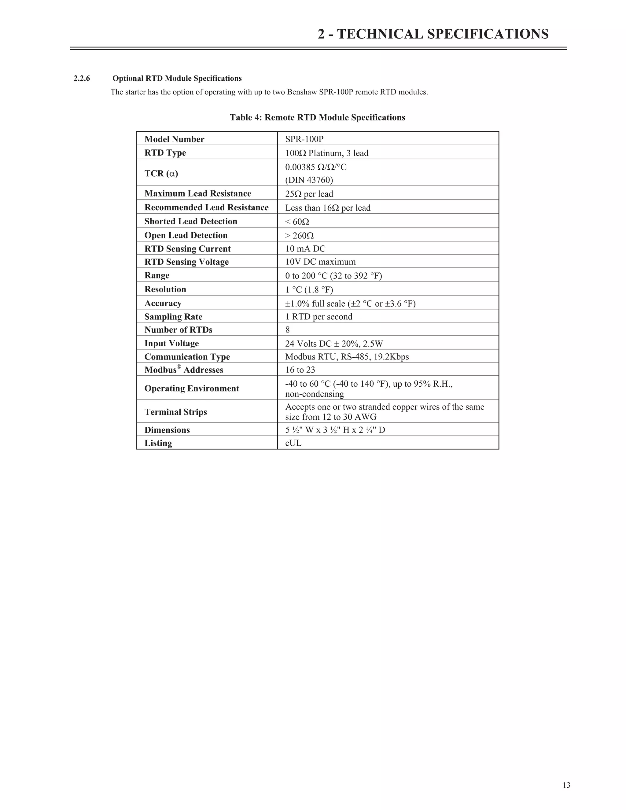
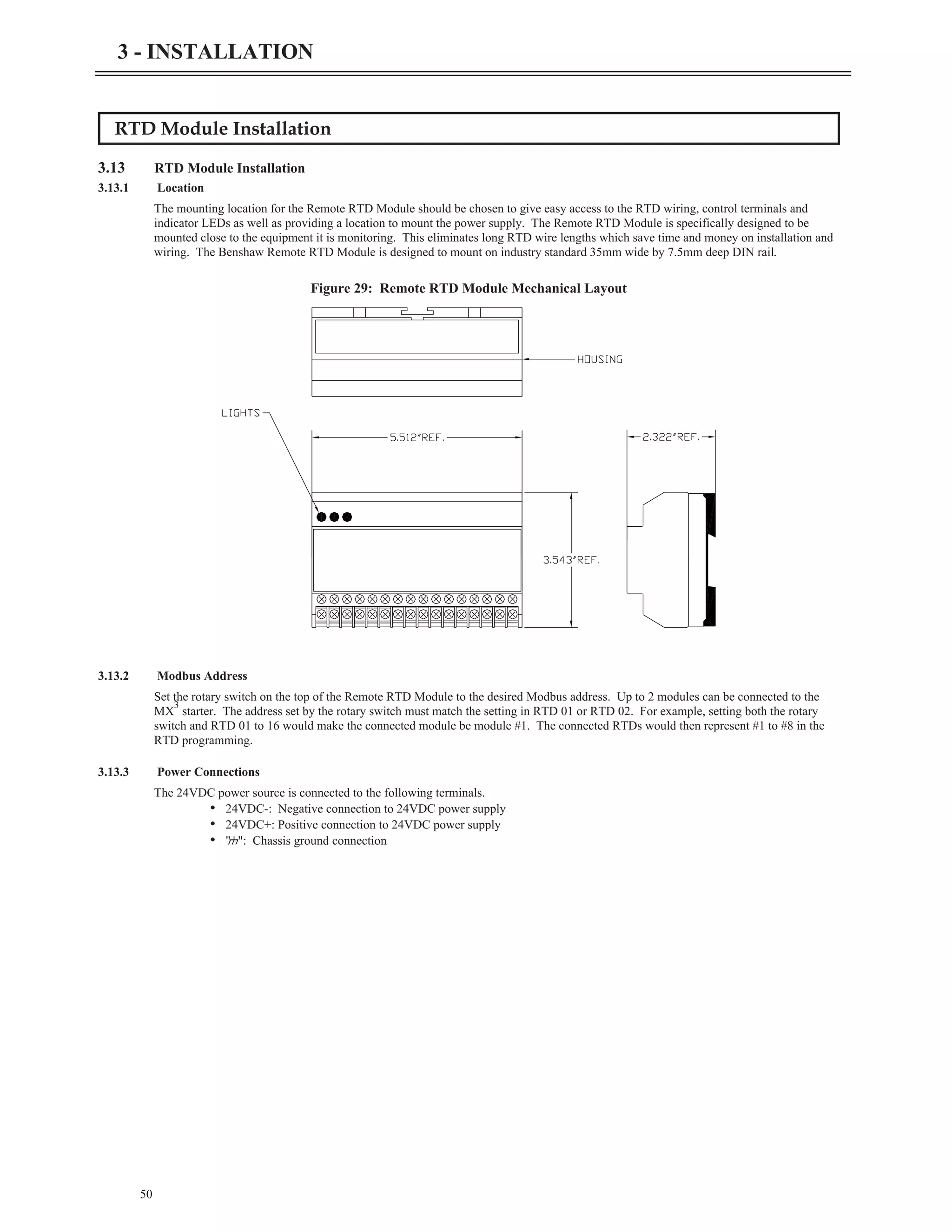
![3.12.3 Display Cutout
49
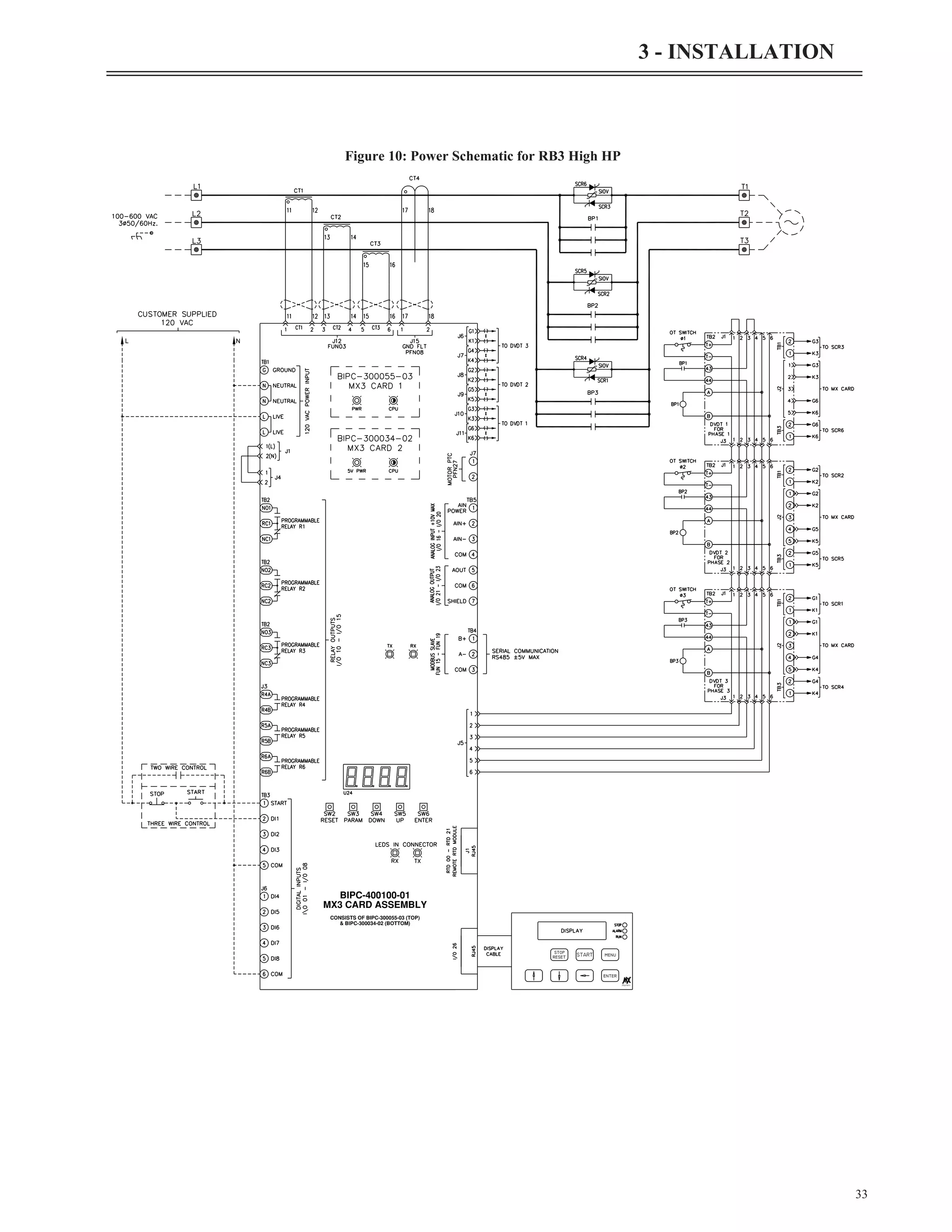
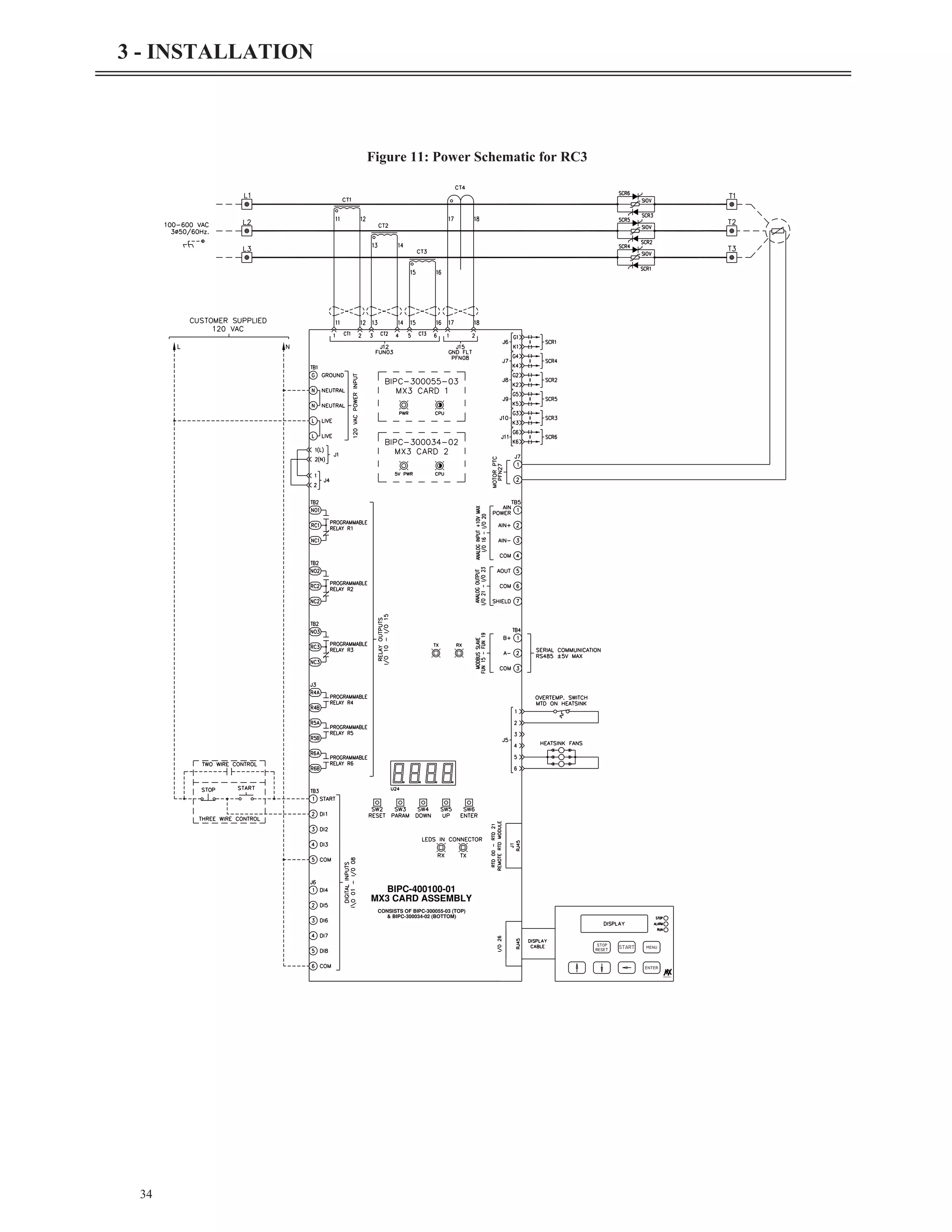
3 - INSTALLATION
50.50
[1.99"]
50.50
[1.99"]
31.50
[1.24"]
31.50
[1.24"]
101.00
[3.98"]
63.00
[2.48"]
Figure 27: Small Display Keypad Mounting Dimensions
Part # : KPMX3SLCD
63.50
[2.50"]
63.50
[2.50"]
38.50
[1.52"]
38.50
[1.52"]
127.00
[5.00"]
77.00
[3.03"]
Figure 28: Large Display Keypad Mounting Dimensions
Part # : KPMX3LLCD](https://image.slidesharecdn.com/01-890034-02-00-lv-mx3-user-manual-1-210614135928/75/01-890034-02-00-lv-mx3-user-manual-1-57-2048.jpg)
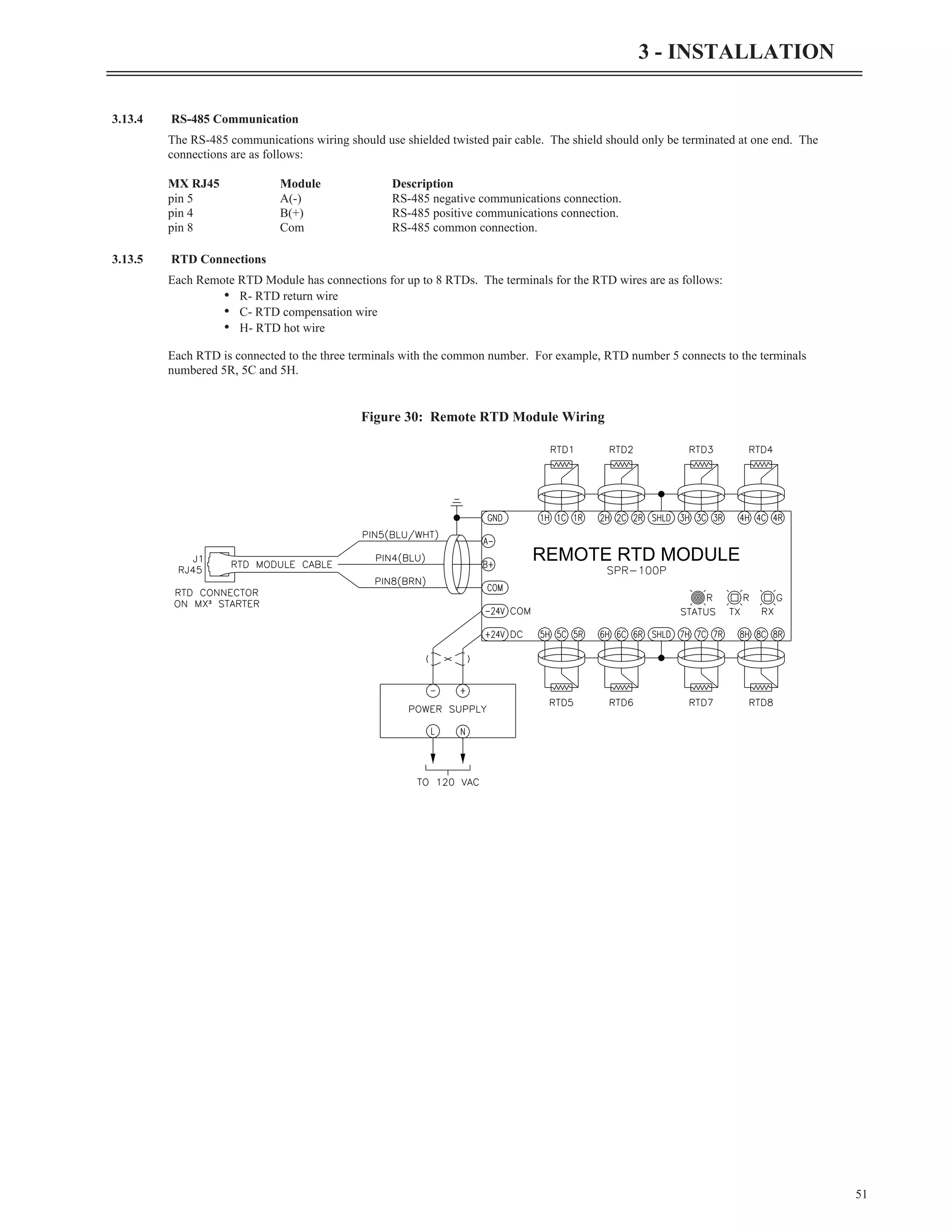
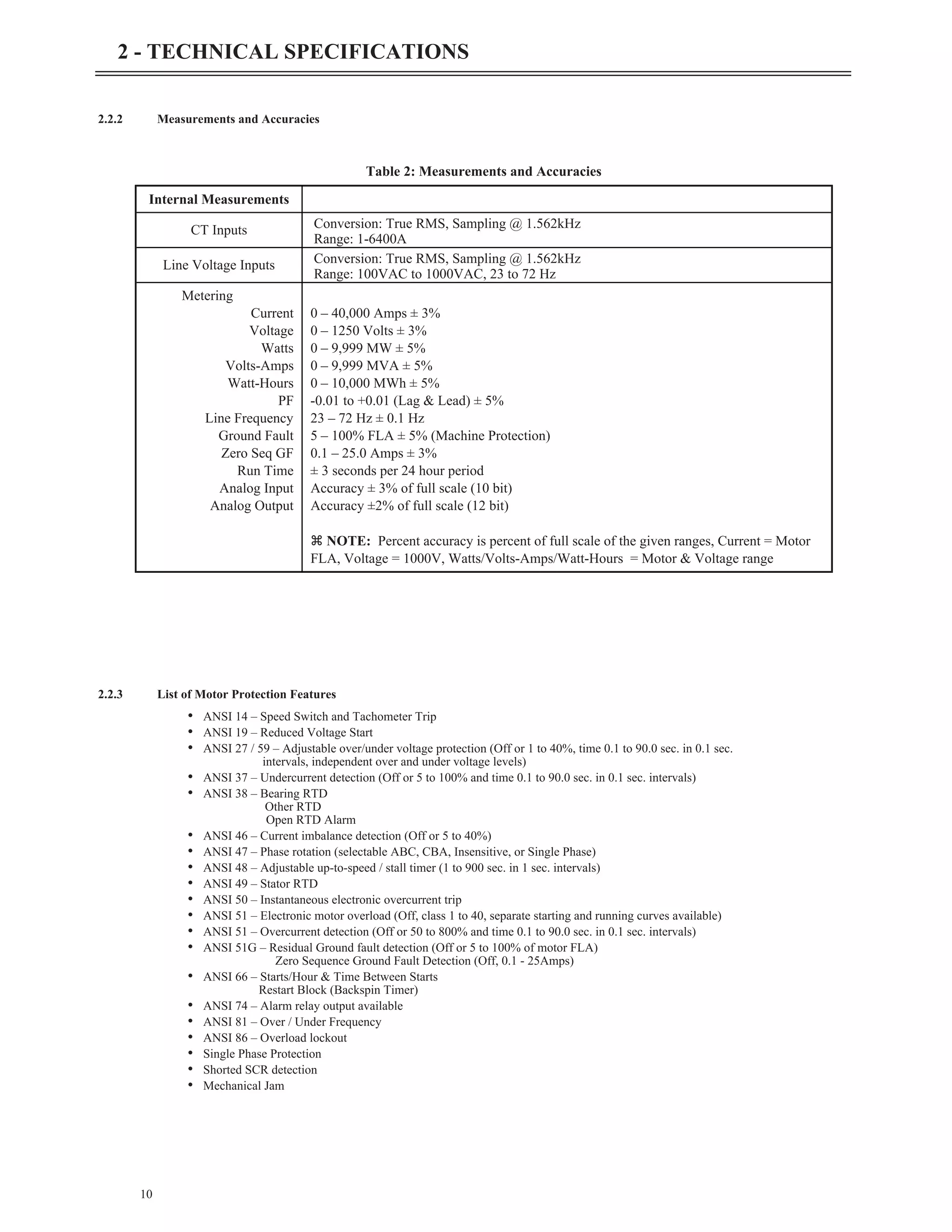
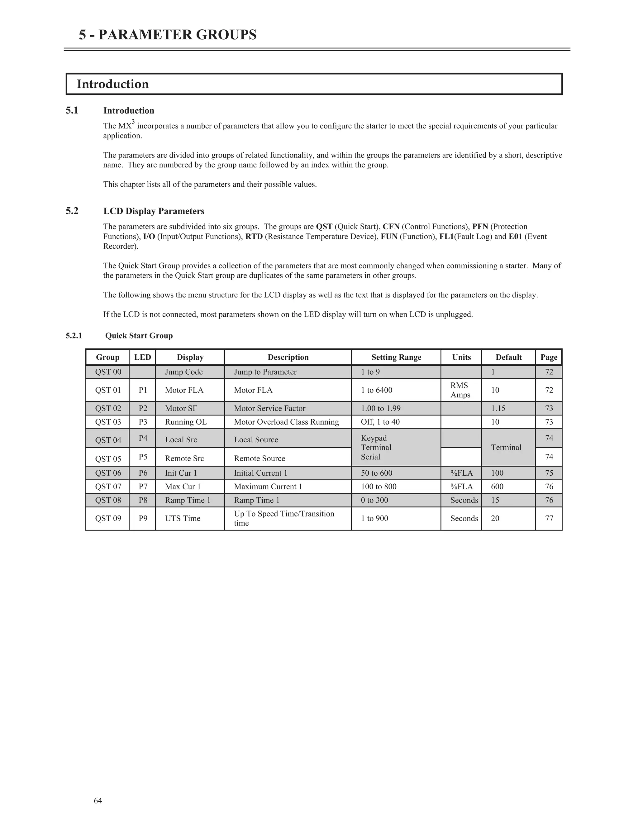
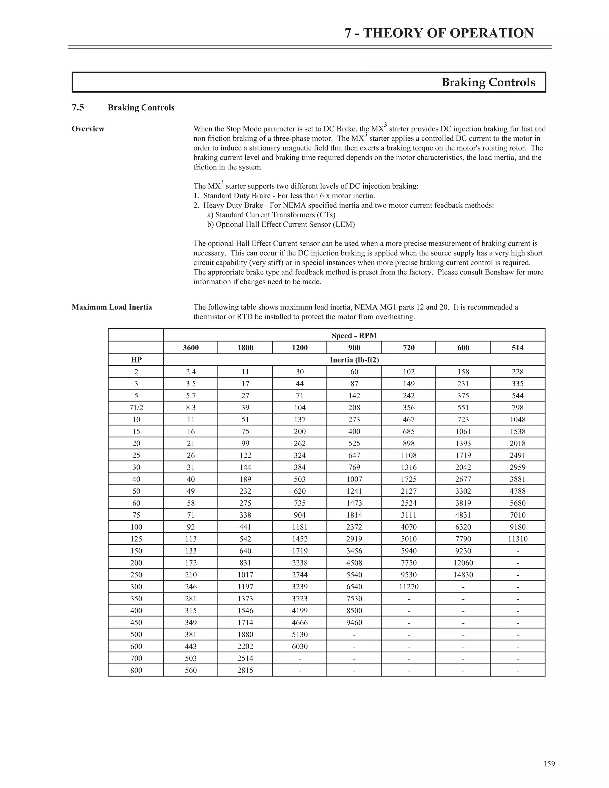
![Introduction
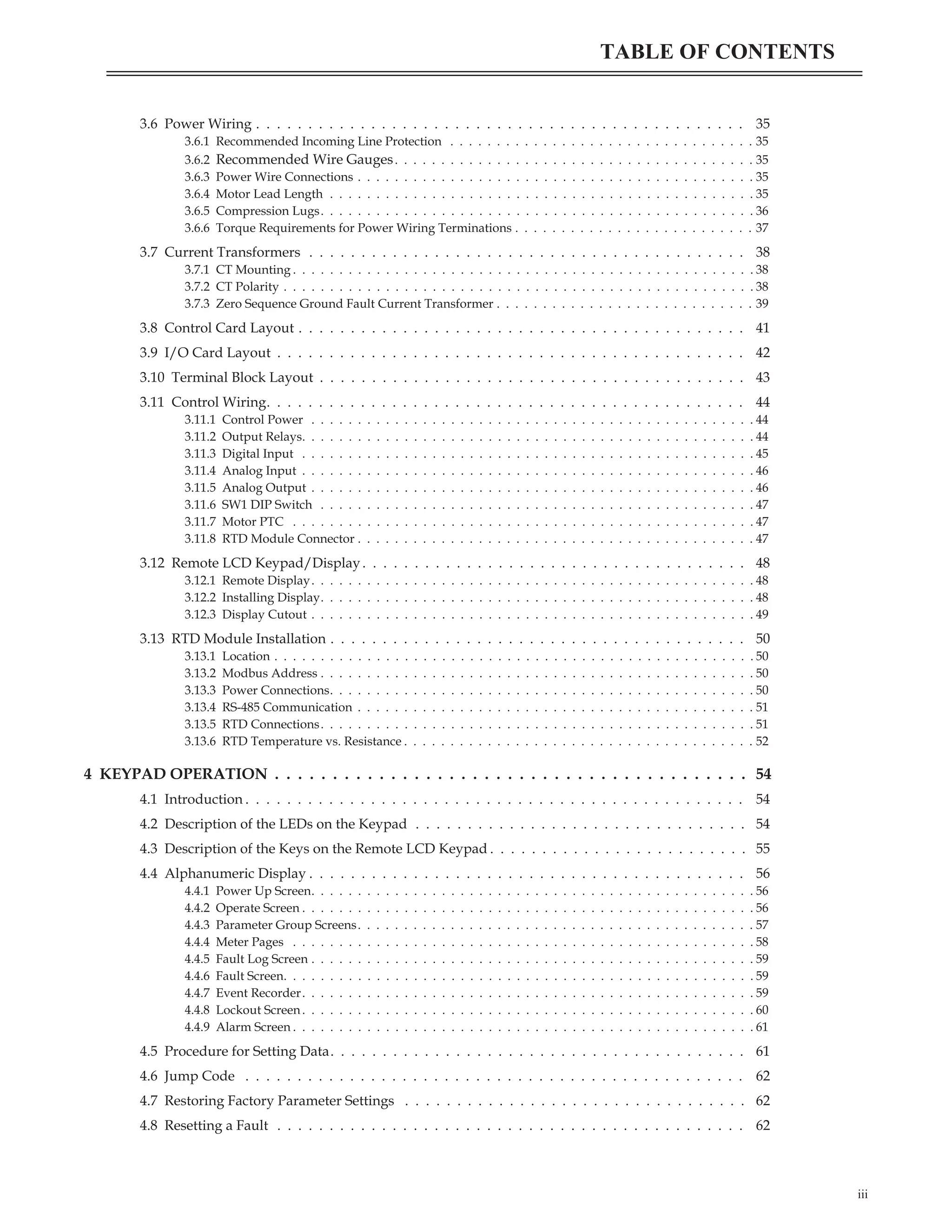
4.1 Introduction
The MX
3
has a 2x16 character, back-lit LCD display/keypad that may be mounted remotely from the MX
3
control card. The remote
LCD keypad has menu, enter, up, down, left, start and stop/reset keys.
The display has keys such as [START], [STOP], and a [LEFT] arrow for moving the cursor around in the LCD display. Status indicators
provide additional information for the starter operation. Extended parameters are also added.
The remote keypad is NEMA 13 / IP65 when mounted directly on the door of an enclosure with the correct gasket.
Description of the LEDs on the Keypad
4.2 Description of the LEDs on the Keypad
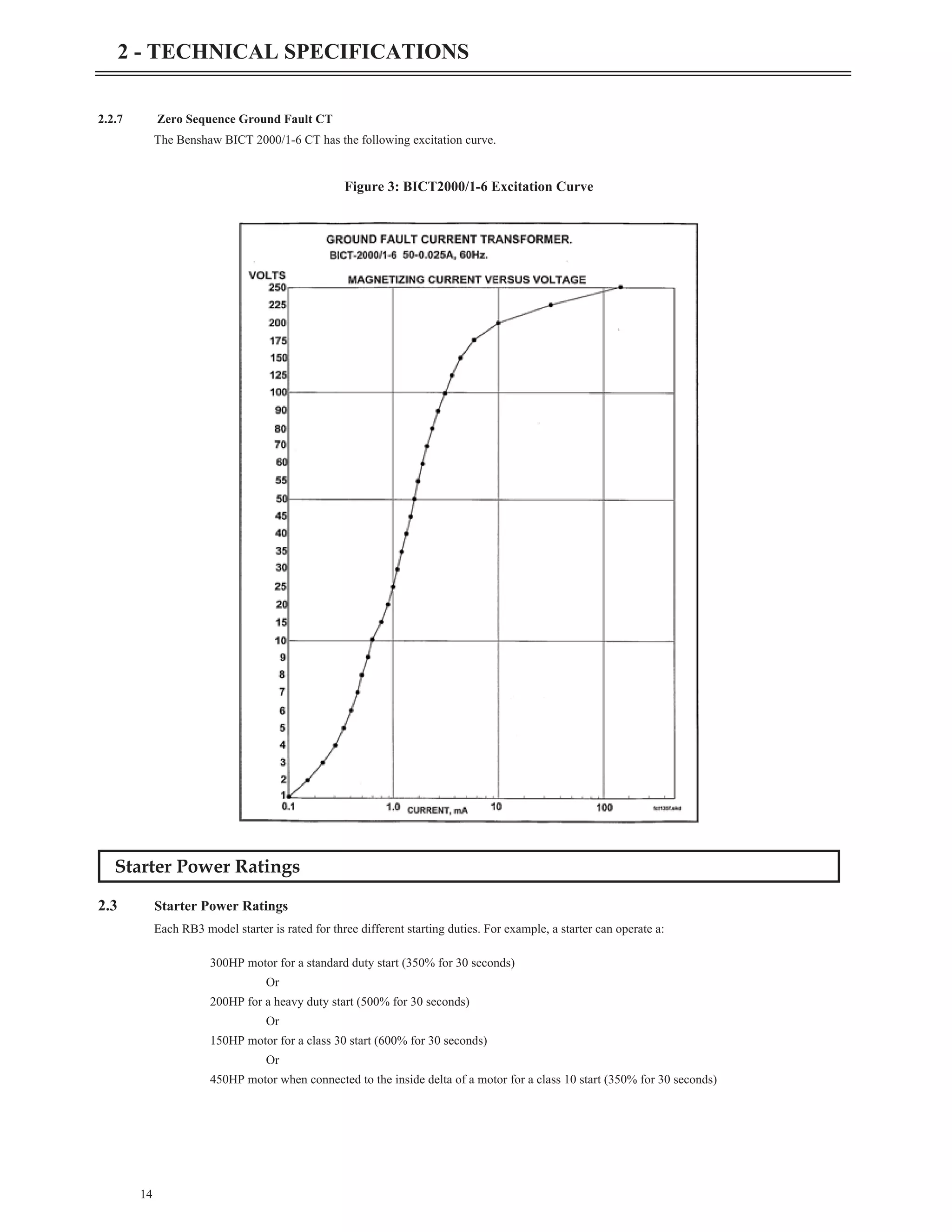
The keypad provides three LED indicators in addition to the 2x16 character display. The LEDs provide starter status information.
z NOTE: By default, the [STOP] key is always active, regardless of selected control source (Local Source and Remote Source
parameters). It may be disabled though using the Keypad Stop Disable (I/O26) parameter. For more information refer to the Keypad
Stop Disable (I/O26) parameter on page 119.
54
4 - KEYPAD OPERATION
Figure 31 - Remote LCD Keypad
LED State Indication
STOP
On Stopped
Flashing Faulted
RUN
On Running and up-to-speed
Flashing Running and not up-to-speed (ramping, decelerating, braking etc).
ALARM Flashing Alarm condition exists. If condition persists, a fault occurs.
Table 18: Remote Keypad LED Functions](https://image.slidesharecdn.com/01-890034-02-00-lv-mx3-user-manual-1-210614135928/75/01-890034-02-00-lv-mx3-user-manual-1-62-2048.jpg)
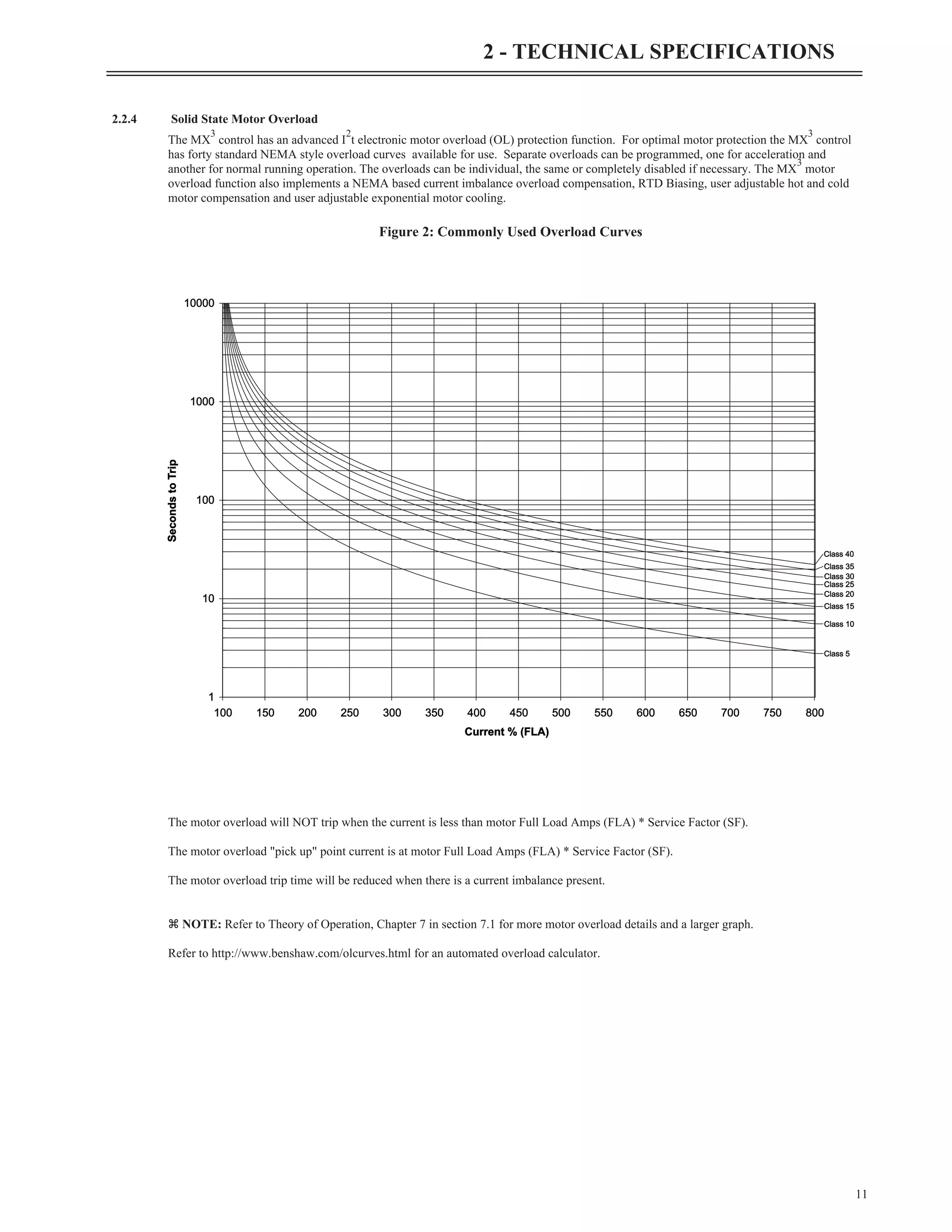
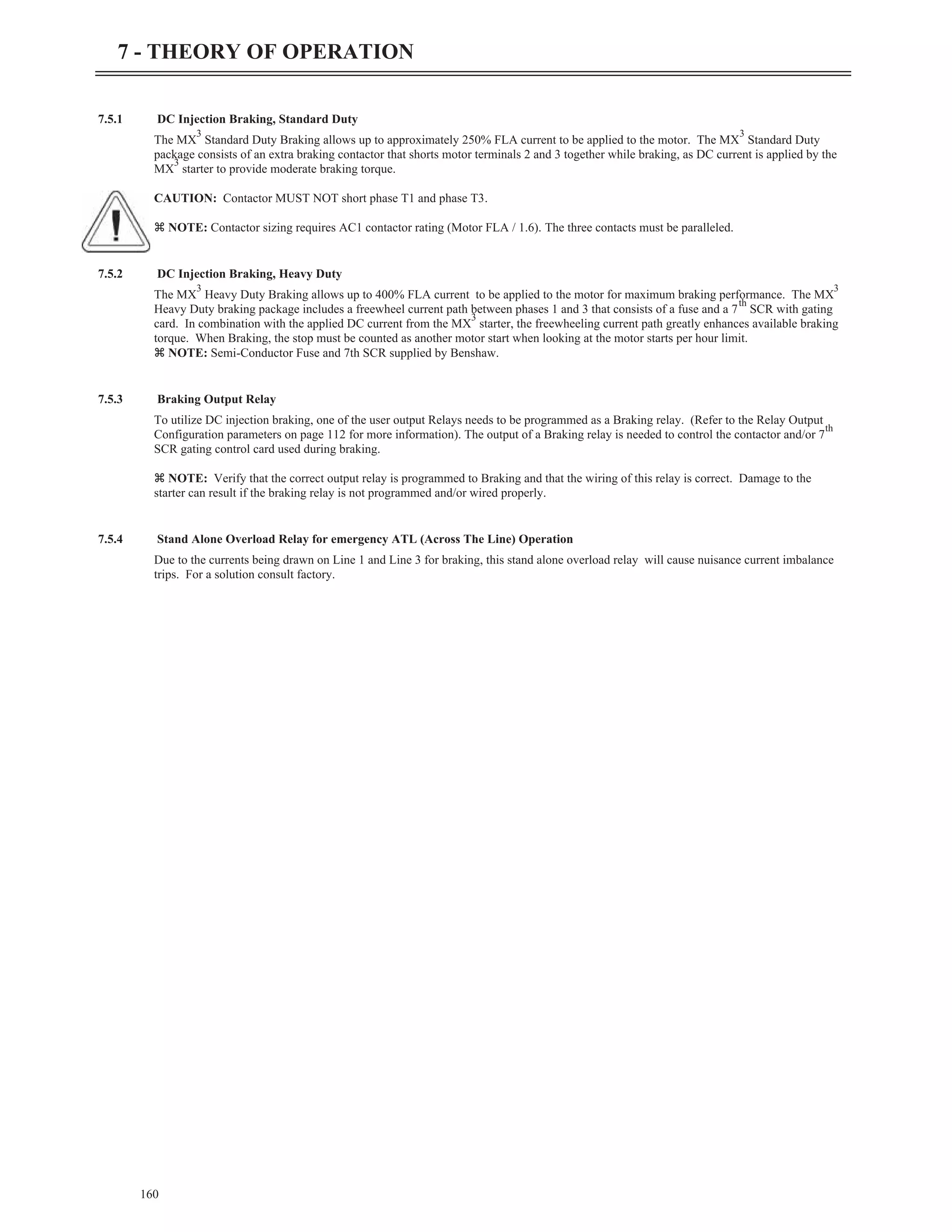
![Description of the Keys on the Remote LCD Keypad
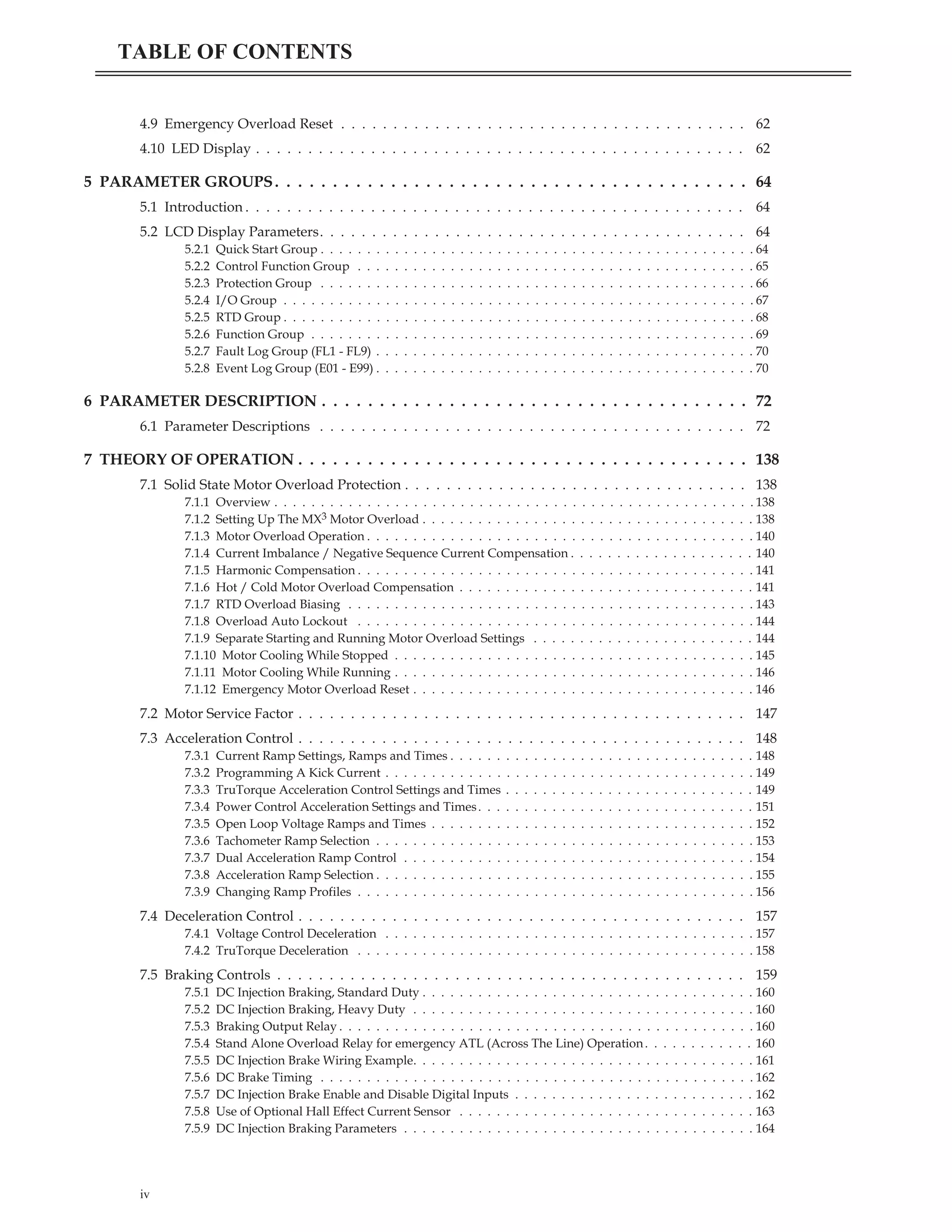
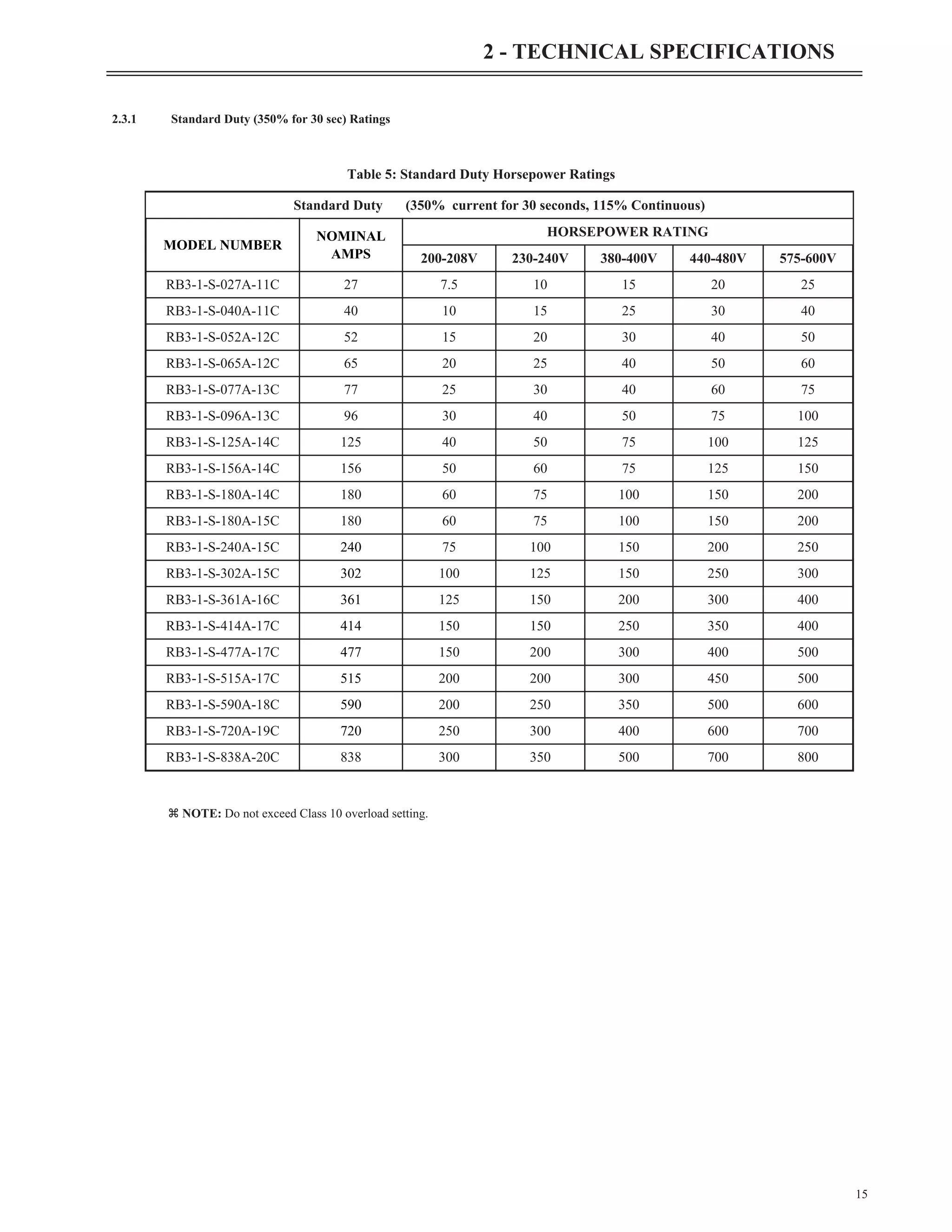
4.3 Description of the Keys on the Remote LCD Keypad
55
4 - KEYPAD OPERATION
Key Function
• This key causes the starter to begin the start sequence. The direction is dependent on wiring and phase
selection.
• In order for this key to work, the Local Source (QST04) parameter must be set to "Keypad".
• Increase the value of a numeric parameter.
• Select the next value of an enumerated parameter.
• It scrolls forward through a list of parameters within a group (when the last parameter is displayed, it
scrolls to the beginning of the list).
• When a list of faults is displayed, it moves from one fault to the next.
• When a list of events is displayed, it moves from one event to the next.
• When the starter is in the Operate Mode, pressing [UP] allows you to change which group of meter
values is monitored.
• Decrease the value of a numeric parameter.
• Select the previous value of an enumerated parameter.
• It scrolls backward through a list of parameters within a group (when the first parameter is displayed,
it scrolls to the end of the list).
• When a list of faults is displayed, it moves from one fault to the previous fault.
• When a list of events is displayed, it moves from one event to the previous event.
• When the starter is in the Operate Mode, pressing [Down] allows you to change which group of meter
values is monitored.
• When editing a numeric parameter, the [LEFT] arrow key moves the cursor one digit to the left. If
cursor is already at the most significant digit, it returns to the least significant digit on the right.
• When in Menu mode, the [LEFT] arrow allows groups to be scrolled through in the opposite direction
of the [MENU] Key.
• Stores the change of a value.
• When in Fault History, [ENTER] key scrolls through information logged when a fault occurred.
• When in Event History, [ENTER] key scrolls through information logged when an event occurred.
• When an alarm condition exists, [ENTER] scrolls through all active alarms.
• [MENU] scrolls between the operate screen and the available parameter groups.
• When viewing a parameter, pressing [MENU] jumps to the top of the menu.
• When a parameter is being edited and [MENU] is pressed, the change is aborted and the parameter’s
old value is displayed.
• The [STOP/RESET] key halts the operation of the starter (Stop Key).
• If a fault has occurred, the [STOP] key is used to clear the fault (Reset Key).
• The [STOP/RESET] key always halts the operation of the starter if the control source is set to
"Keypad". If the control source (QST 04/QST 05) is not set to "Keypad", [STOP] key may be
disabled using the Keypad Stop Disable (I/O26) parameter.
Table 19: Function of the Keys on the LCD Keypad
start
enter
menu
stop
reset](https://image.slidesharecdn.com/01-890034-02-00-lv-mx3-user-manual-1-210614135928/75/01-890034-02-00-lv-mx3-user-manual-1-63-2048.jpg)
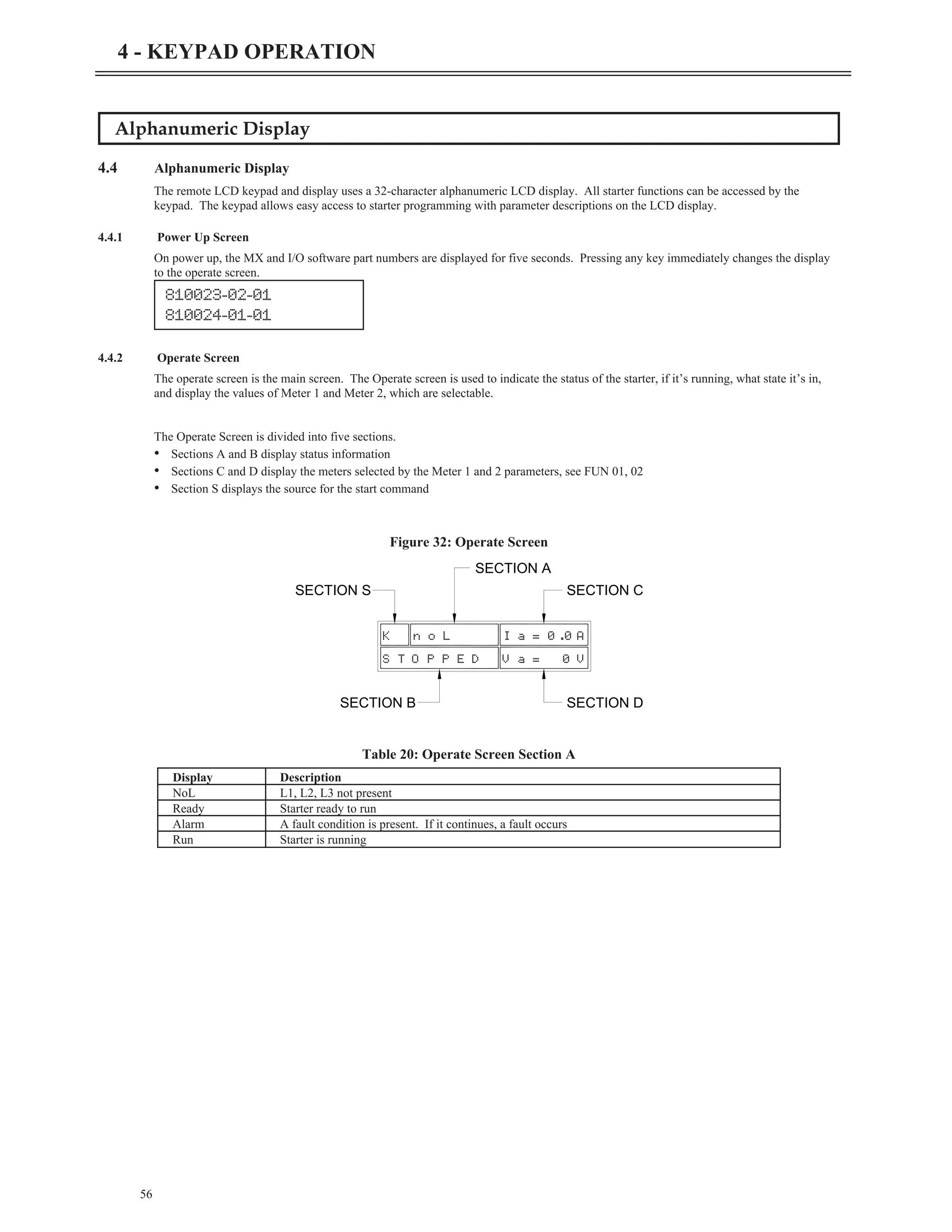
![4.4.4 Meter Pages
Although any meter may be viewed by changing the two meter parameters (FUN 01, FUN 02), there are 19 “Meter Pages” that are easily
accessed to view all of the meter information. These meter pages are scrolled through by pressing the [UP] or [DOWN] down arrows
from the operate screen.
z NOTE: Run Hours00:00 – 23:59
Run Days 0 – 2730 days or 7.5 years
kWatt Hours 0 – 999
MWatt Hours 0 – 9999
Starts 0 – 65535
RS Gnd Cur % motor FLA
58
4 - KEYPAD OPERATION
Current I2= 0.0A
I1= 0.0 I3= 0.0A
Run Days = xxxx
RunHours =xx:xx
Voltage V2= 0V
V1= 0 V3= 0V
Analog In = 0.0%
Analog Out= 0.0%
MWattHour= 0
kWattHour= 0
Starts =xxxxx
Watts = 0
VA = 0
Temps Ts= ---
To= --- Tb= ---
Motor PF =0.00
vars = 0
1= Off 3= Off
2= Off 4= Off
TruTorque = 0%
Power = 0%
5= Off 7= Off
6= Off 8= Off
Overload = 0%
CurrImbal = 0.0%
9= Off 11= Off
10=Off 12= Off
RS Gnd Cur= 0%
ZS Gnd Cur= 0.0A
13= Off 15= Off
14= Off 16= Off
Lst St Tim= xx.xs
Pk St Cur = xx.xA
hh:mm:ssA/P
dd/mm/yy
Frequency = 0.0H
Phase =noL](https://image.slidesharecdn.com/01-890034-02-00-lv-mx3-user-manual-1-210614135928/75/01-890034-02-00-lv-mx3-user-manual-1-66-2048.jpg)
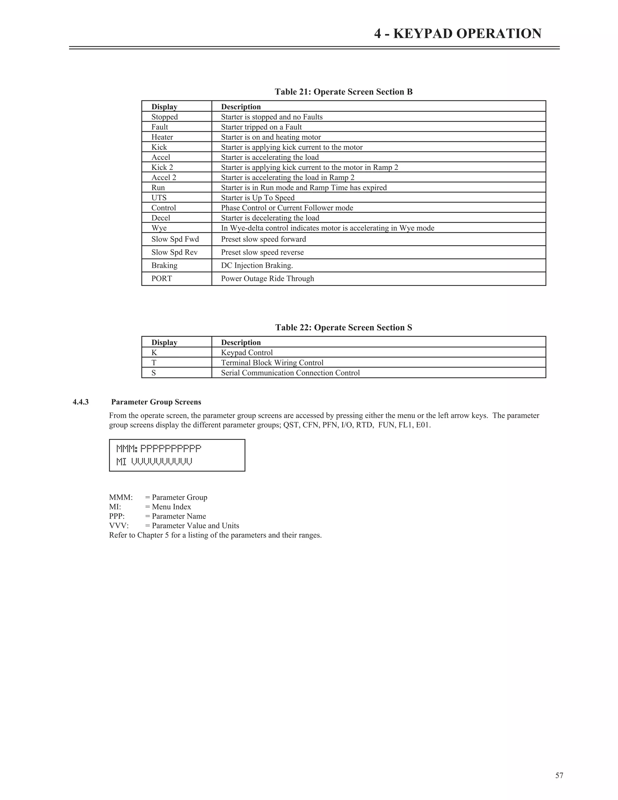
![4.4.5 Fault Log Screen
Information regarding each fault is available through the remote MX
3
LCD display.
FL _: = Fault Log Number. FL1 is the most recent fault and FL9 is the oldest fault.
Fault _ _ = Fault Code
NNN… = Fault Name, or the condition when the fault occurred.
Press [MENU] until you get to the FL1 parameter.
Pressing the [UP] and [DOWN] keys navigates through older and newer faults in the log.
When you get to your fault on the screen begin pressing the [ENTER] key repeatedly. This will rotate through the steps below to show
the conditions the starter was in when the fault occurred.
4.4.6 Fault Screen
When a Fault occurs, the main screen is replaced with a fault screen. The screen shows the fault number and the name of the fault. The
main status screen is not shown until the fault is reset.
When a fault occurs, the STOP LED flashes.
z NOTE: For a list of the Faults, refer to Appendix C - Fault Codes on page 205.
4.4.7 Event Recorder
An event is anything that changes the present state of the starter. Examples of events include a start, a stop, an overload alarm or a fault.
The event recorder stores the last 99 events.
Press [MENU] until you get to the E01 parameter.
Pressing [UP] or [DOWN] will scroll through the last 99 events and displays the event or fault code on top, and the event or fault that
changed the starter's state on the bottom.
59
4 - KEYPAD OPERATION
FL#:Fault##
NNNNNNNNNNNNN
Enter Step
1 Fault Description.
2 Status when the fault occurred, Run, Stopped, Accel. etc.
3 The L1 current at the time of the fault.
4 The L2 current at the time of the fault.
5 The L3 current at the time of the fault.
6 L1-2 voltage at the time of the fault.
7 L2-3 voltage at the time of the fault.
8 L3-1 voltage at the time of the fault.
9 kW at the time of the fault.
10 Frequency at the time of the fault.
11 Run time since last run time reset.
Fault##
FaultName
E##: Event###
Event](https://image.slidesharecdn.com/01-890034-02-00-lv-mx3-user-manual-1-210614135928/75/01-890034-02-00-lv-mx3-user-manual-1-67-2048.jpg)
![Pressing [ENTER] gives the starter state condition at the time of event.
Press [ENTER] again to give you the time of the event.
Press [ENTER] again to give you the date that the event occurred.
z NOTE: After pressing [ENTER] you can shift through all the different starter states, times and dates by using the [UP] and [DOWN]
arrows.
4.4.8 Lockout Screen
When a lockout is present, one of the following screens will be displayed. The main status screen is not shown until the lockout is
cleared.
The overload lockout displays the overload content and the time until reset if an overload occurs.
The stack over temperature lockout will be displayed if a stack over temperature is detected.
The control power lockout will be displayed if the control power is not within specifications.
The disconnect open lockout will be displayed if a digital input is programmed to "disconnect" and the input is not on.
The time between starts lockout displays the time until the next start is allowed when PFN21 is programmed.
The backspin timer lockout displays the time until the next restart when PFN20 is programmed.
The starts per hour lockout displays the time until the next start is allowed when PFN22 is programmed.
The motor PTC lockout is displayed when the motor thermistor is overheated or defective.
The RTD lockout displays the hottest RTD that tripped the starter.
The communications loss is displayed when the starter loses communication with the remote RTD modules.
The open lockout is displayed when the RTD module senses an open RTD.
60
4 - KEYPAD OPERATION
Overload Lockout 96%
XX:XX
Stack Overtemp
Lockout
Control Power
Lockout
Disconnect Open
Lockout
Time btw Starts
Lockout XX:XX
Backspin Timer
Lockout XX:XX
Starts per Hour
Lockout XX:XX
Motor PTC
Lockout
RTD Lockout
RTD##= XXXC
RTD Lockout
RTD##commloss
RTD Lockout
RTD##= Open](https://image.slidesharecdn.com/01-890034-02-00-lv-mx3-user-manual-1-210614135928/75/01-890034-02-00-lv-mx3-user-manual-1-68-2048.jpg)
![The short lockout is displayed when the RTD module senses a shorted RTD.
z NOTE: XX:XX is the time remaining until the lockout releases.
4.4.9 Alarm Screen
When an alarm is present, the word “Alarm” is displayed on the operate screen. Pressing the [ENTER] key displays more information
about the alarm.
Procedure for Setting Data
4.5 Procedure for Setting Data
Select a parameter that is to be changed. To change Motor FLA from 10 Amps to 30 Amps:
From the main screen:
Press [MENU] key and the display shows QST: (Quick Start) screen.
Press [UP] key once to Motor FLA (QST 01).
Press [ENTER] key once, the cursor starts to flash in the one’s place.
Press [LEFT] key once, the cursor flashes in the ten’s place.
Press [UP] arrow to increase the value, for a value of 30, press twice.
Press [ENTER] to store the value.
Press [UP] arrow to change another parameter in QST.
Press [MENU] to change another parameter in another group.
Press [LEFT] arrow to go back to the main screen.
61
4 - KEYPAD OPERATION
Alarm##
Alarm Name
TReady Ia= 0.0A
Stopped Va= 480V
QST: Jump Code
00 1
QST: Motor FLA
01 10Amp
QST: Motor FLA
01 10Amp
QST: Motor FLA
01 10Amp
QST: Motor FLA
01 30Amp
QST: Motor FLA
01 30Amp
RTD Lockout
RTD##= Sort](https://image.slidesharecdn.com/01-890034-02-00-lv-mx3-user-manual-1-210614135928/75/01-890034-02-00-lv-mx3-user-manual-1-69-2048.jpg)
![Jump Code
4.6 Jump Code
At the beginning of each parameter group, there is a Jump Code parameter. By changing the value of this parameter and pressing
[ENTER], you can jump directly to any parameter within that group.
Restoring Factory Parameter Settings
4.7 Restoring Factory Parameter Settings
Go to the FUN group by pressing [MENU]. Scroll through to FUN 22- Miscellaneous Commands and press [ENTER]. Now set to
"Factory Rst" and press [ENTER]. The display will return to None but the parameters will be reset to the factory defaults.
Below is a list of the minimum parameters that will need to be set again.
FUN 05 (Rated RMS Voltage)
FUN 03 (CT Ratio)
I/O 01 - 08 (Digital Inputs)
I/O 10 - 15 (Relay Outputs)
z NOTE: You must consult the wiring schematic for digital inputs and relay output configuration.
Resetting a Fault
4.8 Resetting a Fault
To reset from a fault condition, press [RESET].
Emergency Overload Reset
4.9 Emergency Overload Reset
To perform an emergency overload reset, press [RESET] and [DOWN] buttons together. This sets the motor overload content to 0.
LED Display
4.10 LED Display
The card mounted LED display can be used to access most of the parameters when the standard remote mounted display is not
connected. The LED parameter numbers (Pxx) are shown in the parameter table. See chapter 5.
62
4 - KEYPAD OPERATION](https://image.slidesharecdn.com/01-890034-02-00-lv-mx3-user-manual-1-210614135928/75/01-890034-02-00-lv-mx3-user-manual-1-70-2048.jpg)

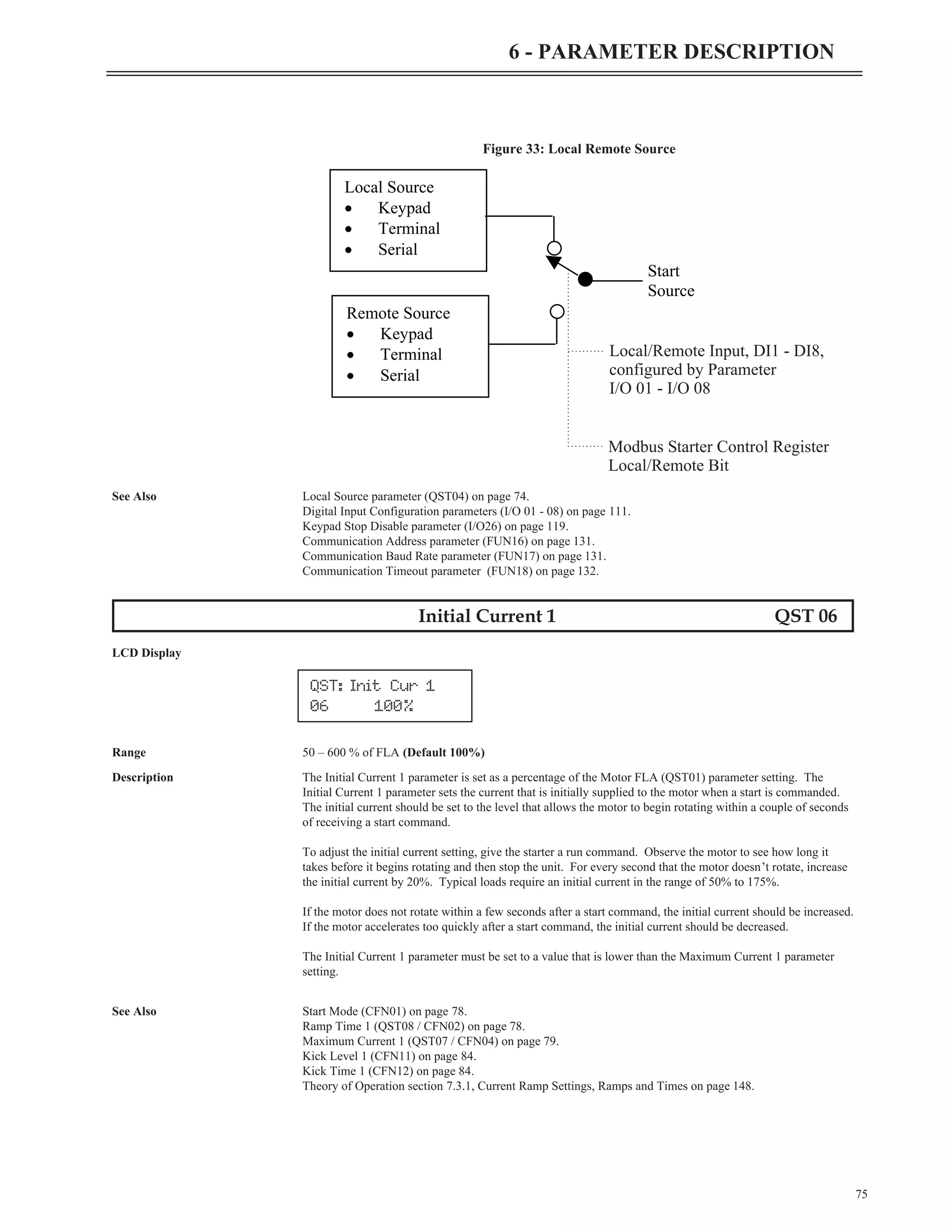
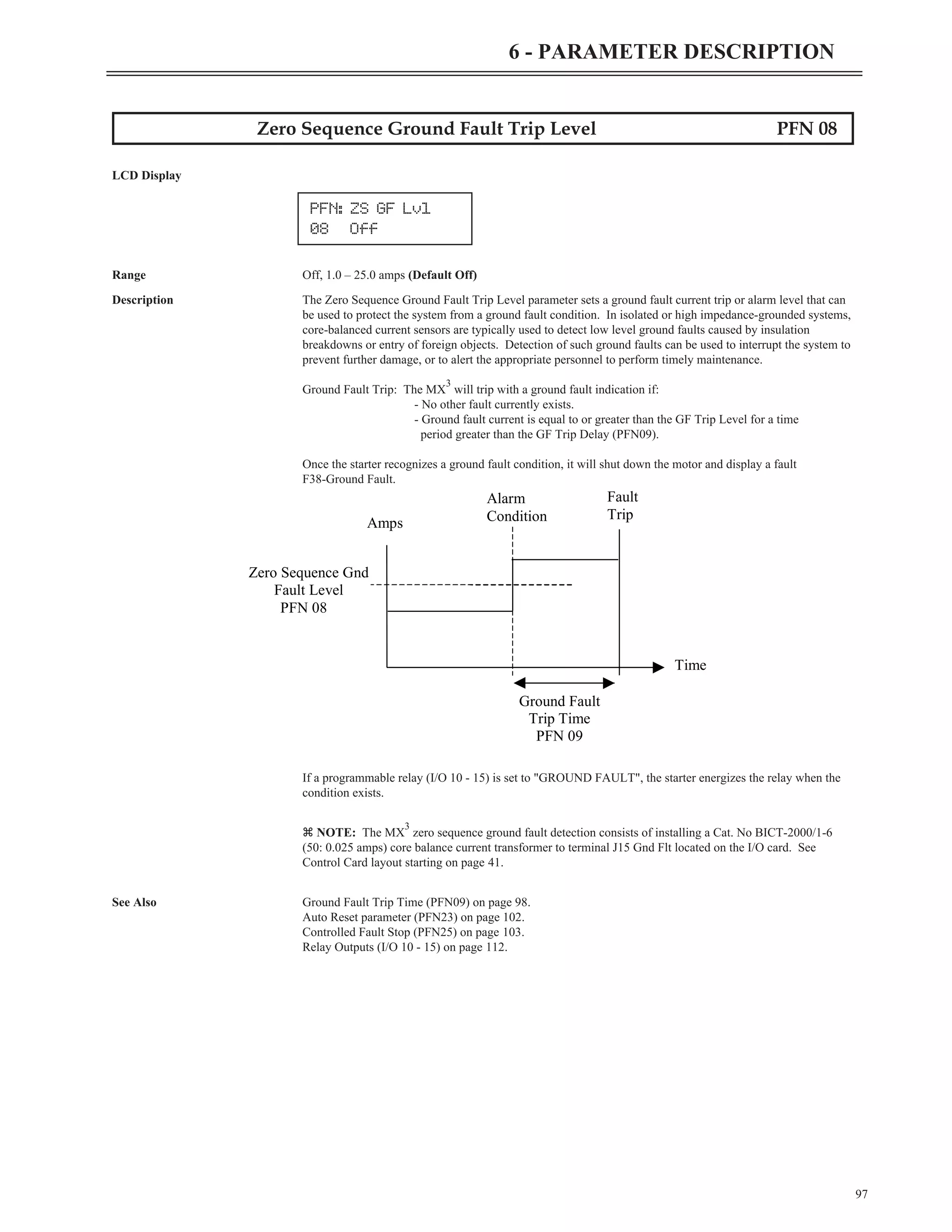
![Parameter Descriptions
6.1 Parameter Descriptions
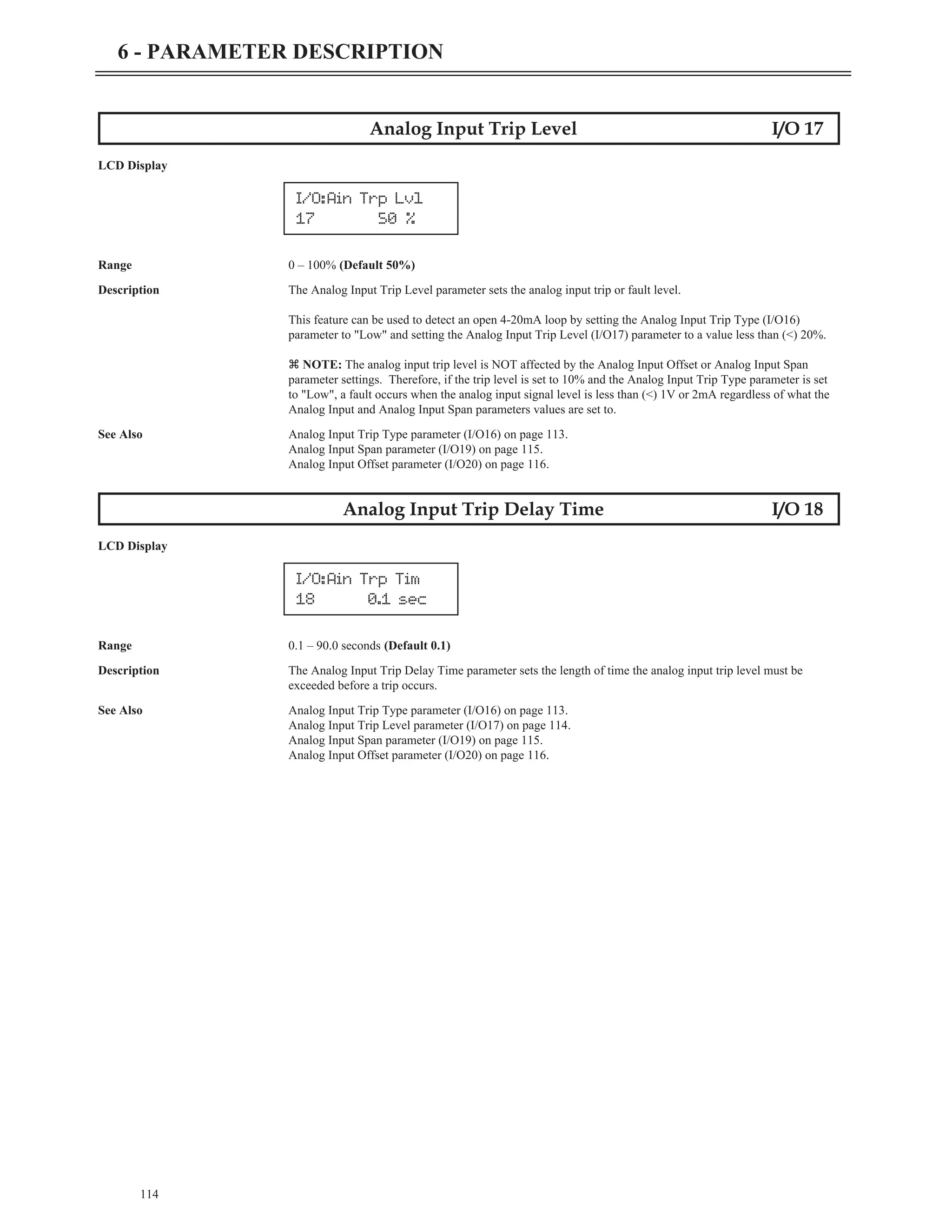
The detailed parameter descriptions in this chapter are organized in the same order as they appear on the LCD display.
Each parameter has a detailed description that is displayed with the following format.
Parameter Name MMM__
LCD Display
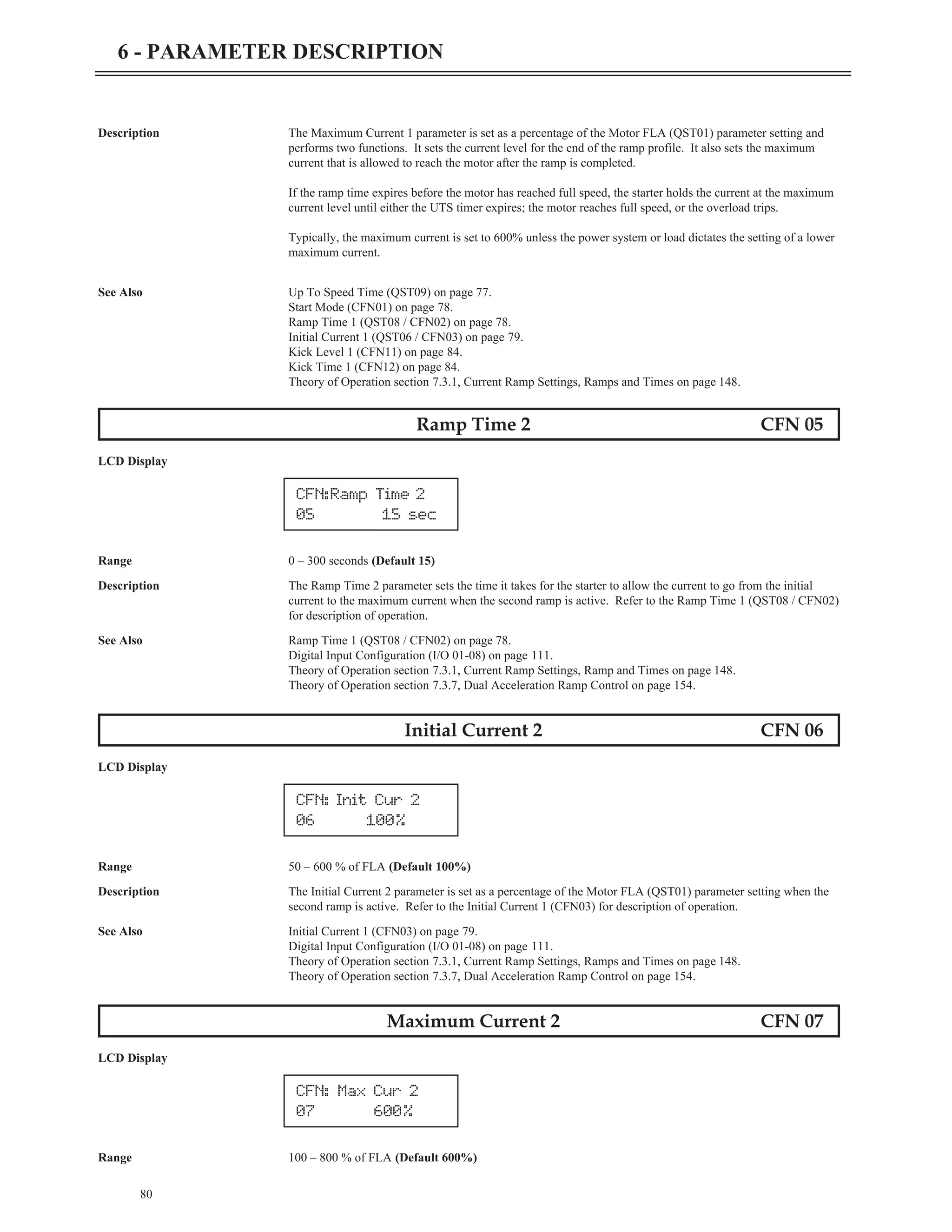
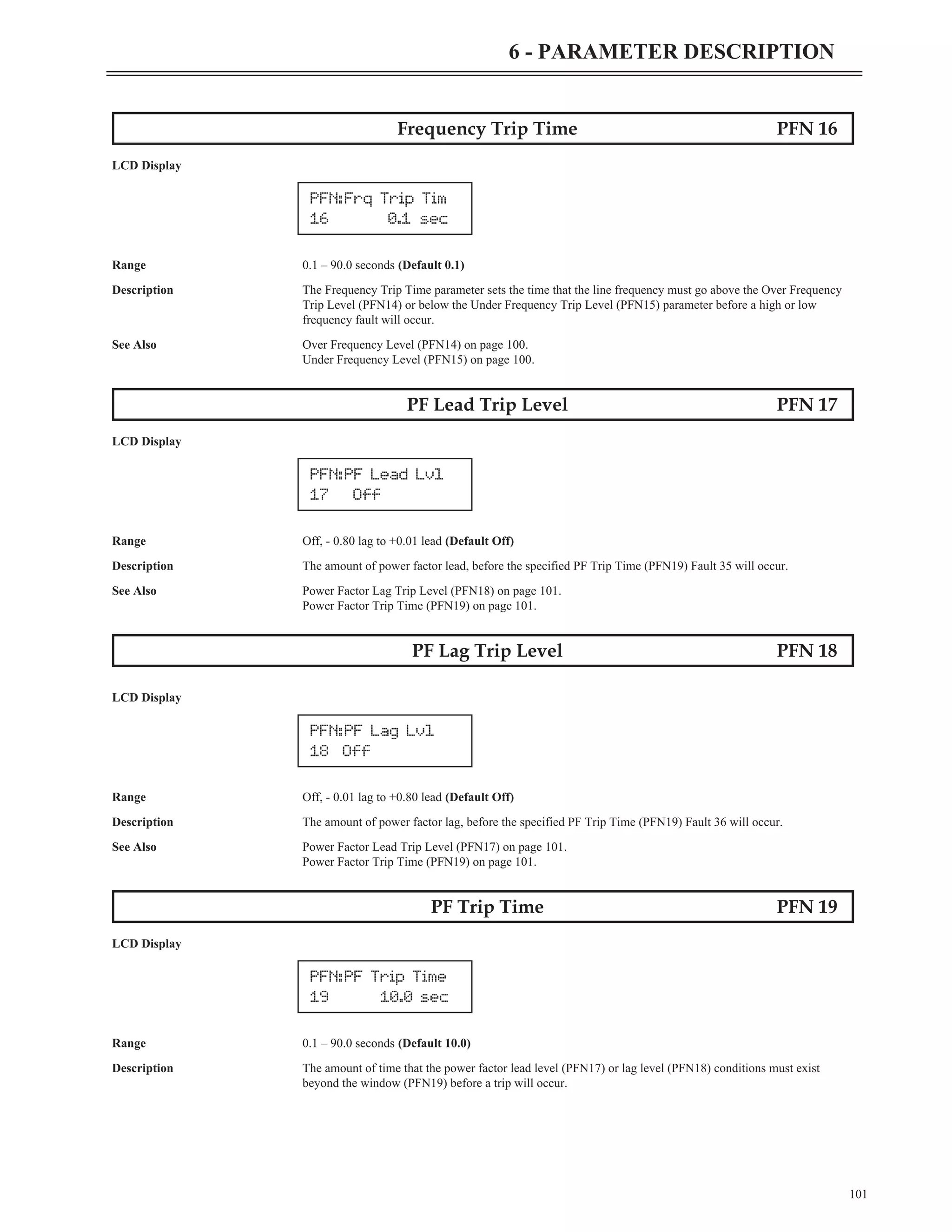
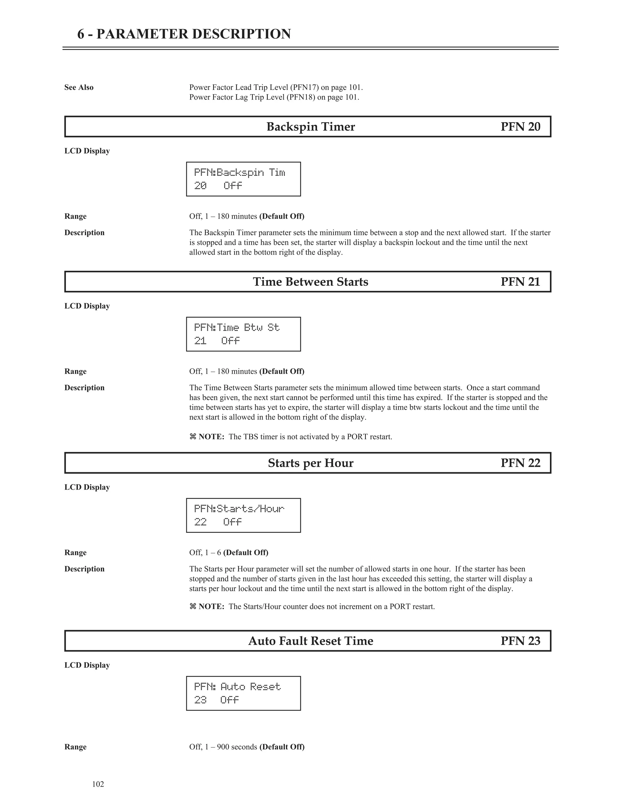
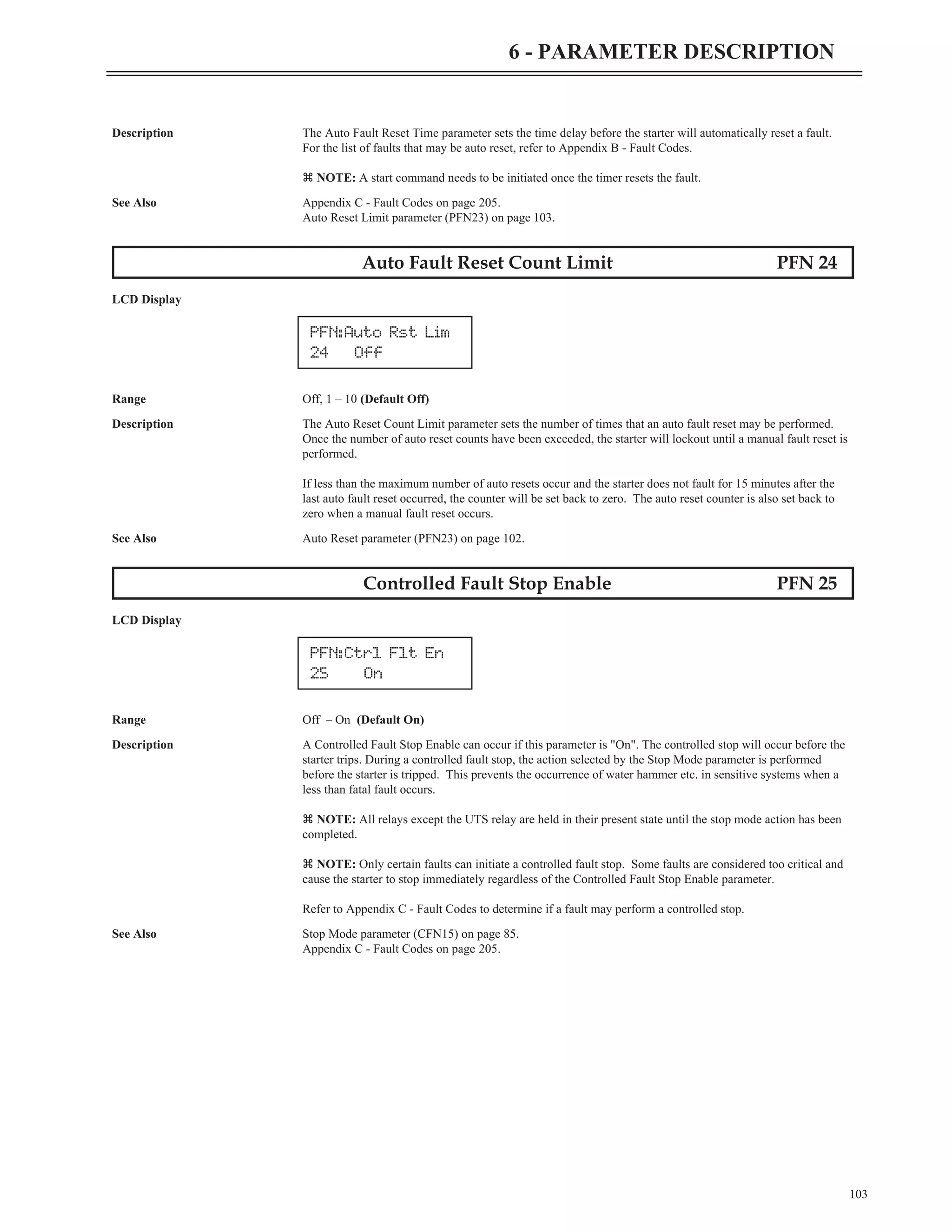
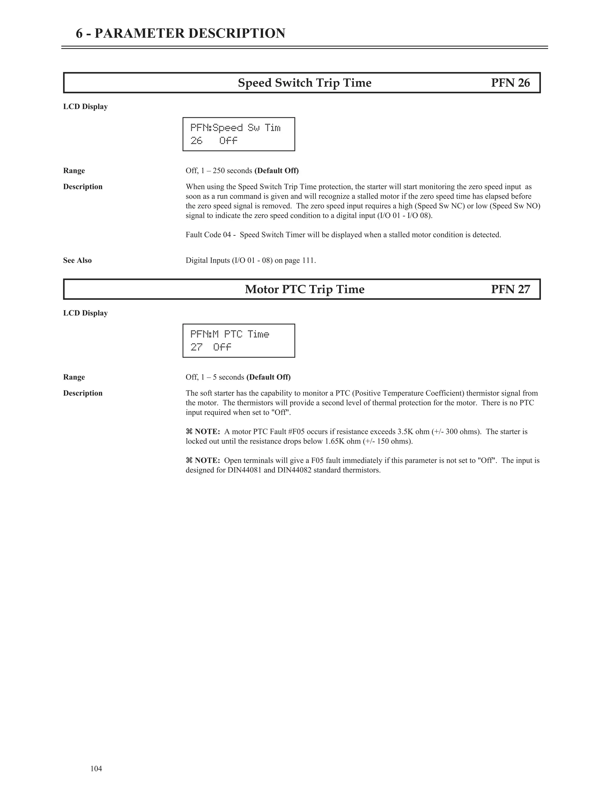
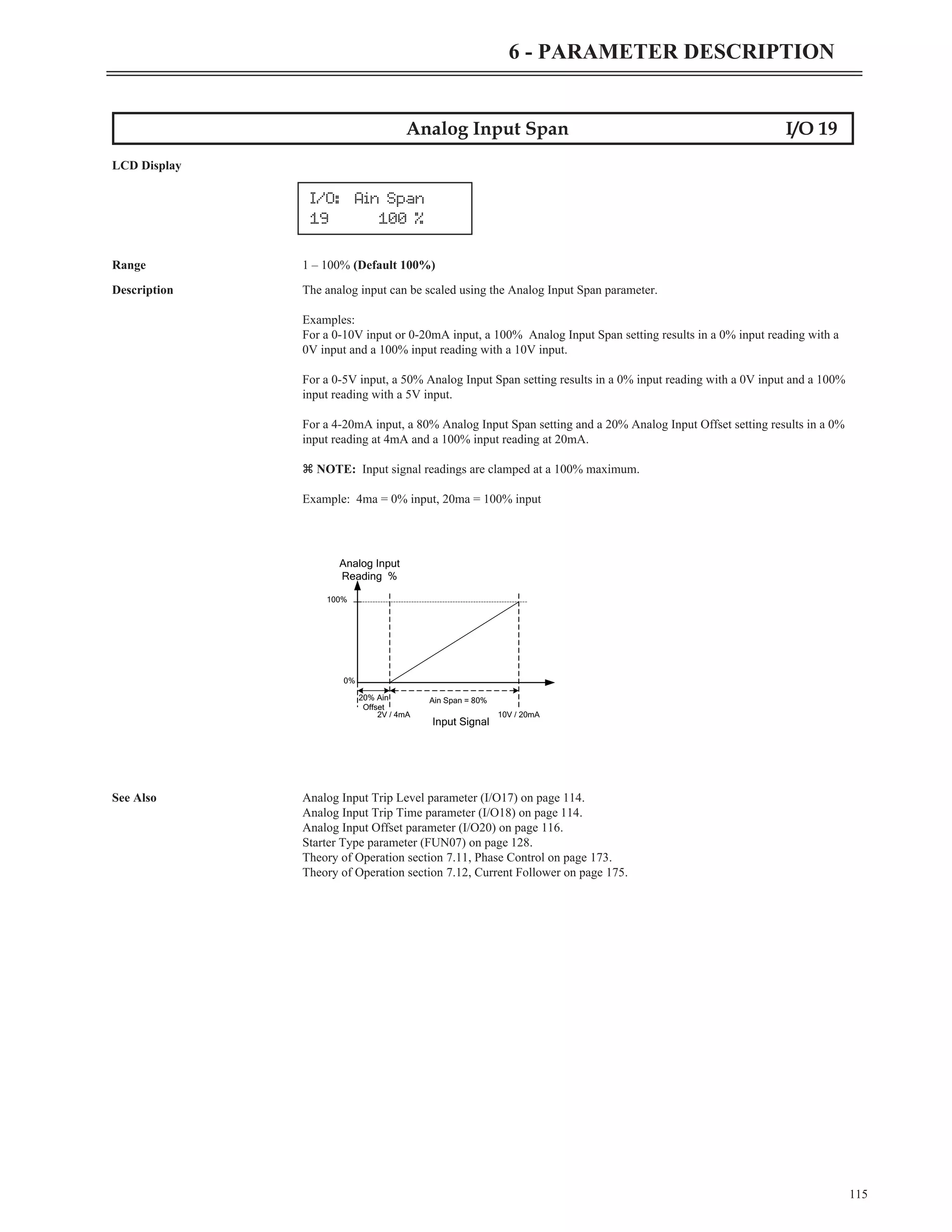
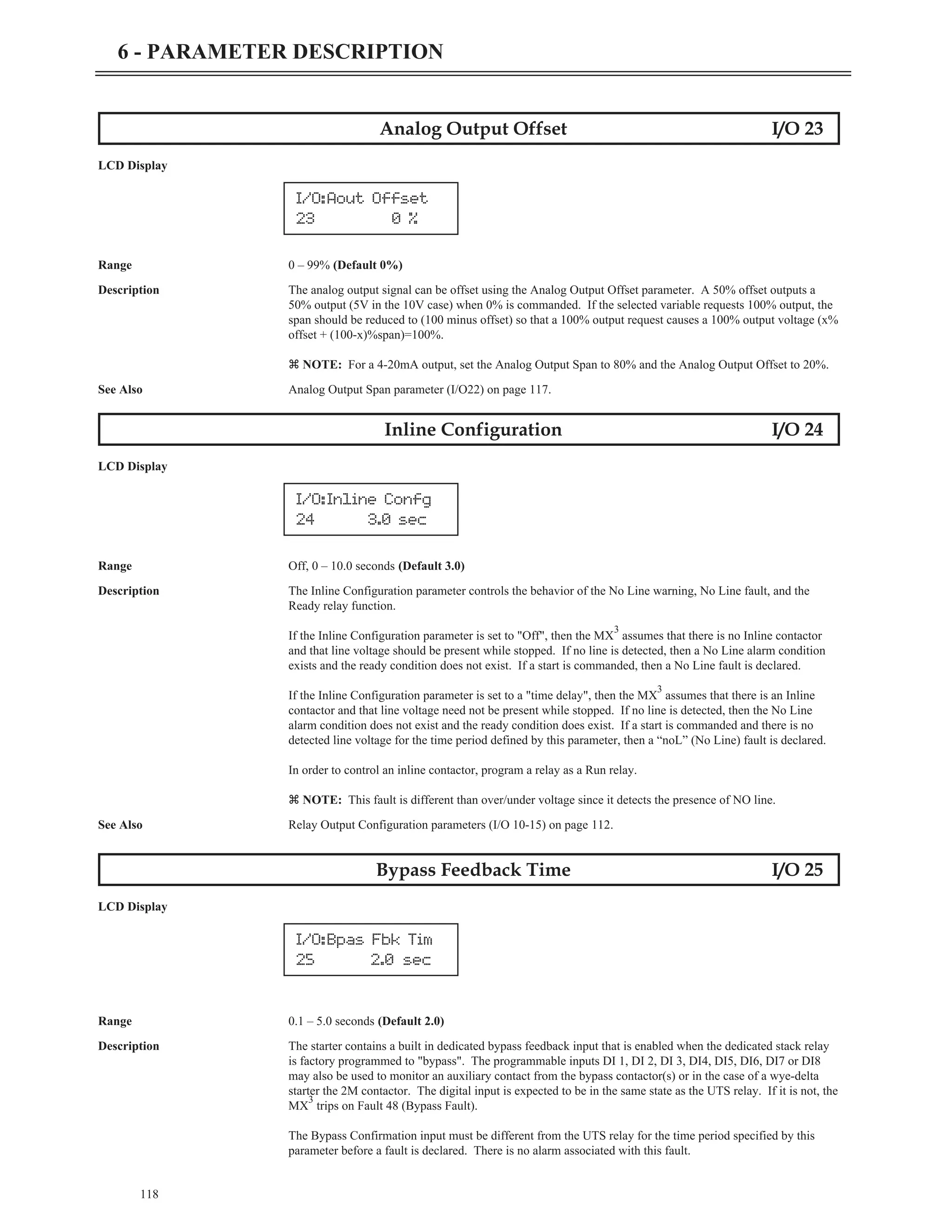
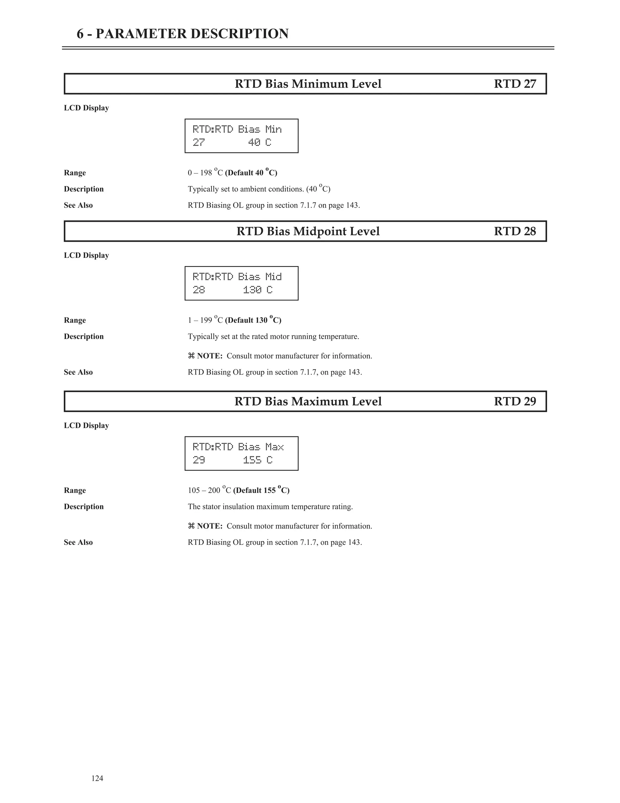
Range Parameter Value (Default: Constant)
OR
LCD
Keypad
Description The description of the function.
See Also Cross references to related parameters or other chapters.
Jump to Parameter QST 00
LCD Display
Description By changing the value of this parameter and pressing [ENTER], you can jump directly to any parameter
within the group.
Motor FLA QST 01
LCD Display
Range 1 – 6400 Amps RMS (Default 10A)
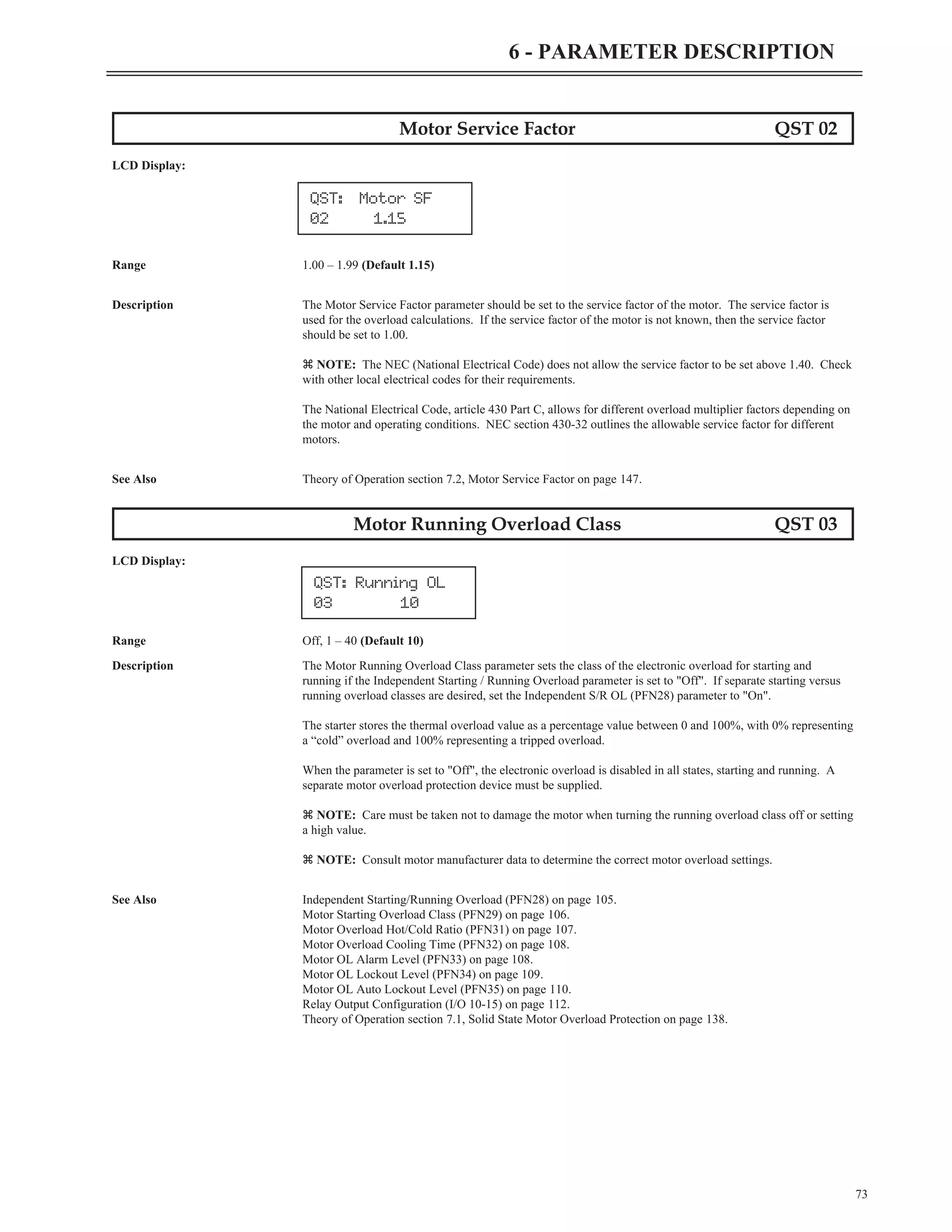
Description The Motor FLA parameter configures the motor full load amps, and is obtained from the nameplate on the
attached motor.
If multiple motors are connected, the FLA of each motor must be added together for this value.
z NOTE: Incorrectly setting this parameter prevents proper operation of the motor overload protection,
motor over current protection, motor undercurrent protection, ground fault protection and acceleration control.
72
6 - PARAMETER DESCRIPTION
MMM: Parameter
MI Value
QST: Motor FLA
01 10Amp
QST: Jump Code
00 1](https://image.slidesharecdn.com/01-890034-02-00-lv-mx3-user-manual-1-210614135928/75/01-890034-02-00-lv-mx3-user-manual-1-80-2048.jpg)
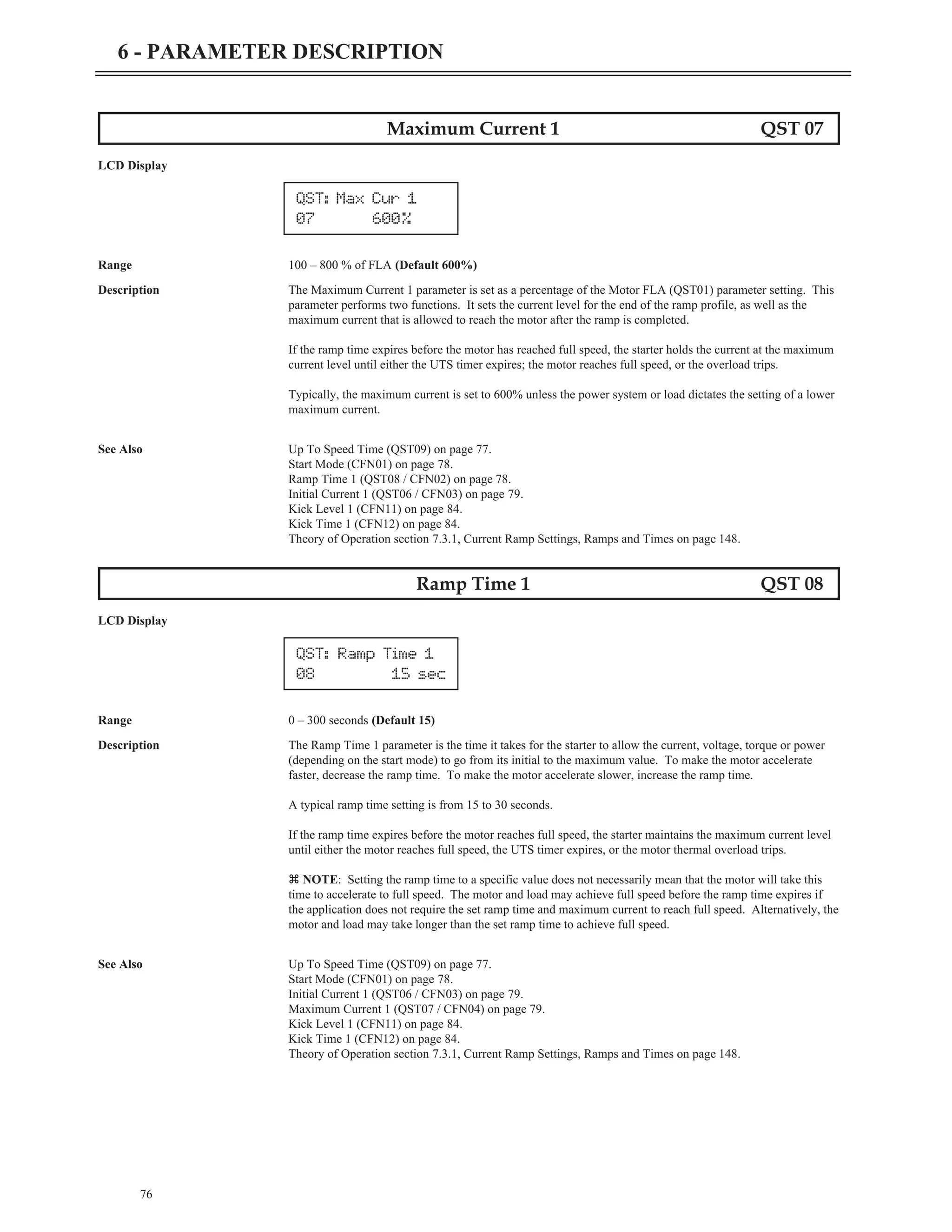
![77
6 - PARAMETER DESCRIPTION
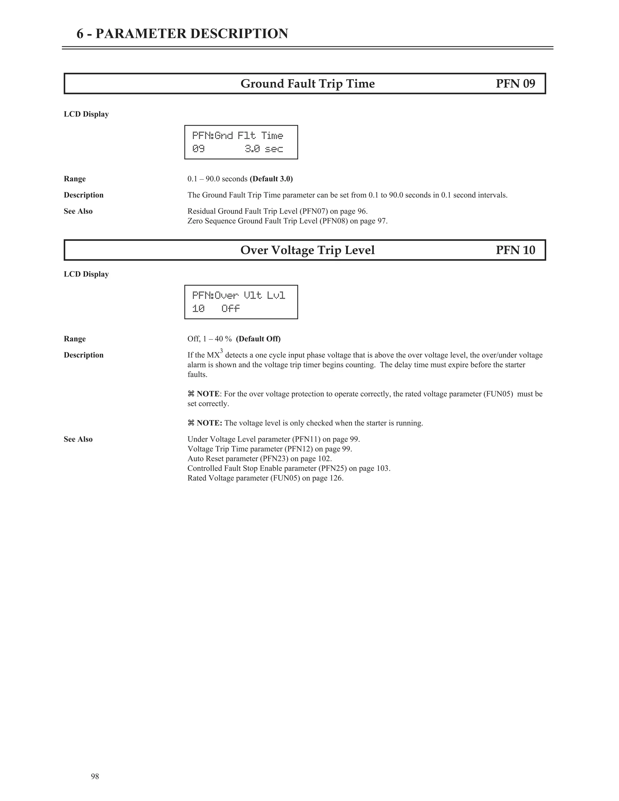
Up To Speed Time QST 09
LCD Display
Range 1 – 300 seconds (Default 20)
Description The Up To Speed Time parameter sets the maximum acceleration time to full speed that the motor can take. A
stalled motor condition is detected if the motor does not get up-to-speed before the up-to-speed timer expires.
The motor is considered up-to-speed once the current stabilizes below 175 percent of the FLA value and the
ramp time expires.
z NOTE: During normal acceleration ramps, the up-to-speed timer has to be greater than the sum of the
highest ramp time in use and the kick time. The up-to-speed timer does not automatically change to be greater
than the ramp time. If a ramp time greater than the up-to-speed timer is set, the starter will declare an
up-to-speed fault every time a start is attempted.
z NOTE: When the Start Mode parameter (CFN01) is set to "Voltage Ramp", the UTS timer acts as an
acceleration kick. When the UTS timer expires, full voltage is applied to the motor. This feature can be used
to reduce motor oscillations if they occur near the end of an open loop voltage ramp start.
z NOTE: When the starter type parameter (FUN07) is set to "Wye-Delta", the UTS timer is used as the
transition timer. When the UTS timer expires, the transition from Wye starting mode to Delta running mode
takes place if it has not already occurred.
Fault Code 01 - Up to Speed Fault is declared when a stalled motor condition is detected.
See Also Start Mode (CFN01) on page 78.
Ramp Time 1 (QST08 / CFN02) on page 78.
Ramp Time 2 (CFN05) on page 80.
Kick Time 1 (CFN12) on page 84.
Kick Time 2 (CFN14) on page 85.
Starter Type (FUN07) on page 128.
Theory of Operation section 7.3, Acceleration Control on page 148.
Theory of Operation section 7.8, Wye-Delta on page 168.
Jump to Parameter CFN 00
LCD Display
Description By changing the value of this parameter and pressing [ENTER], you can jump directly to any parameter
within the group.
CFN: Jump Code
00 1
QST: UTS Time
09 20sec](https://image.slidesharecdn.com/01-890034-02-00-lv-mx3-user-manual-1-210614135928/75/01-890034-02-00-lv-mx3-user-manual-1-85-2048.jpg)
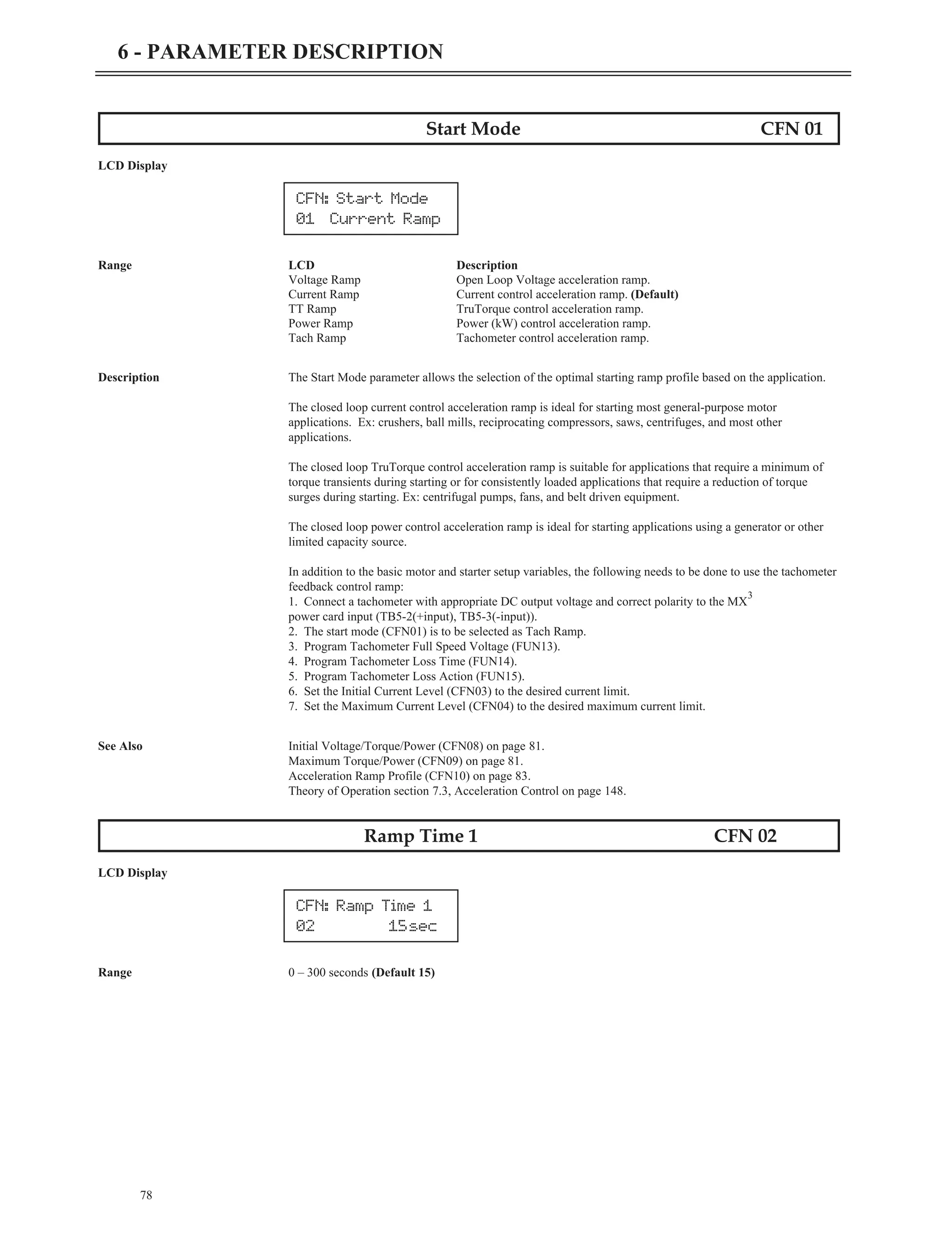
![92
6 - PARAMETER DESCRIPTION
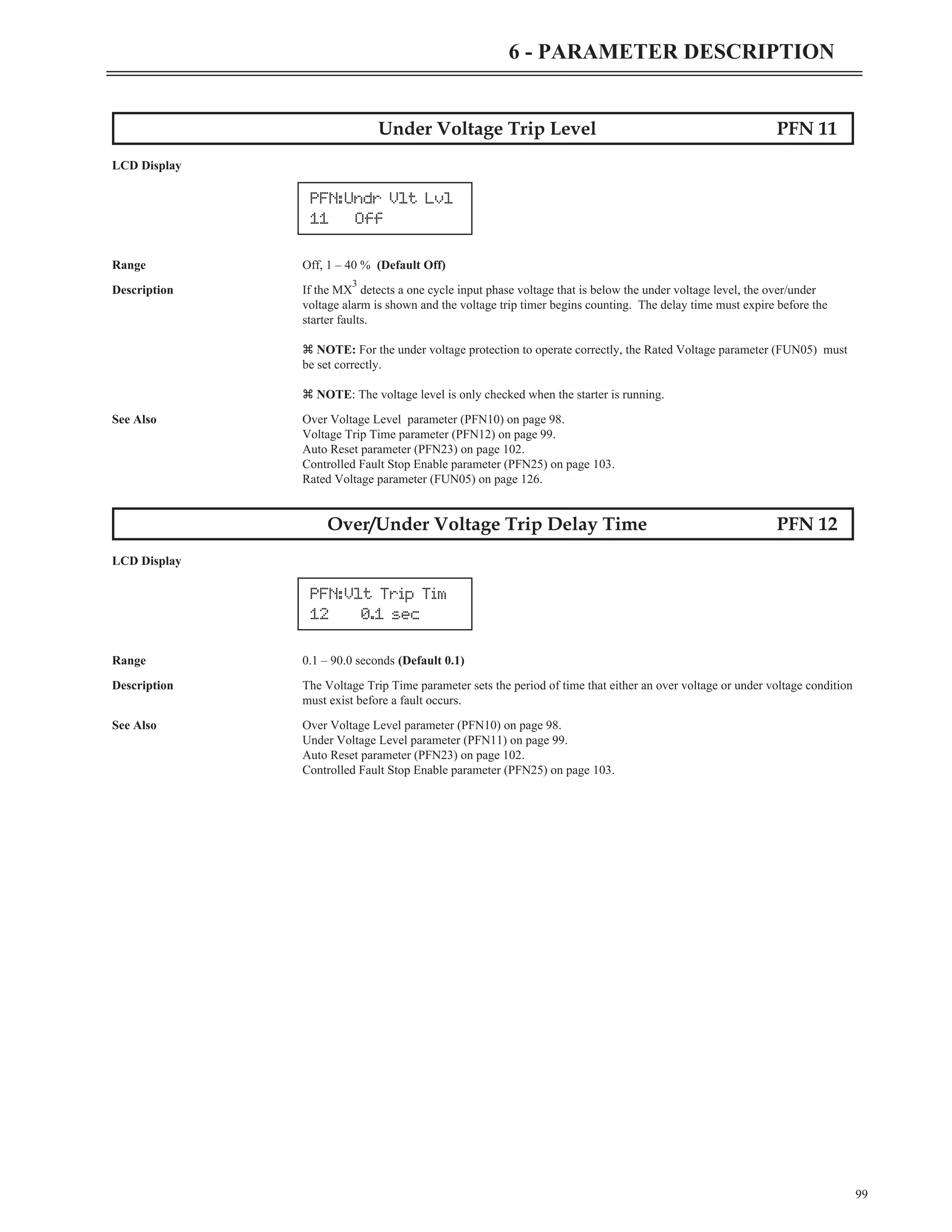
Slow Speed Kick Time CFN 27
LCD Display
Range 0.1 – 10.0 seconds (Default 1.0)
Description The Slow Speed Kick Time parameter sets the length of time that the Slow Speed Kick current level (CFN26)
is applied to the motor at the beginning of slow speed operation. After the Slow Speed Kick Level is set, the
Slow Speed Kick Time should be adjusted so that the motor starts rotating when a slow speed command is
given.
If the motor initially accelerates too fast then reduce the Slow Speed Kick Level and/or reduce the Slow Speed
Kick Time.
See Also Preset Slow Speed (CFN23) on page 90.
Slow Speed Kick Level parameter (CFN26) on page 91.
Motor PTC Trip Time (PFN27) on page 104.
Theory of Operations section 7.6, Slow Speed Operation on page 164.
Jump to Parameter PFN 00
LCD Display
Description By changing the value of this parameter and pressing [ENTER], you can jump directly to any parameter
within the group.
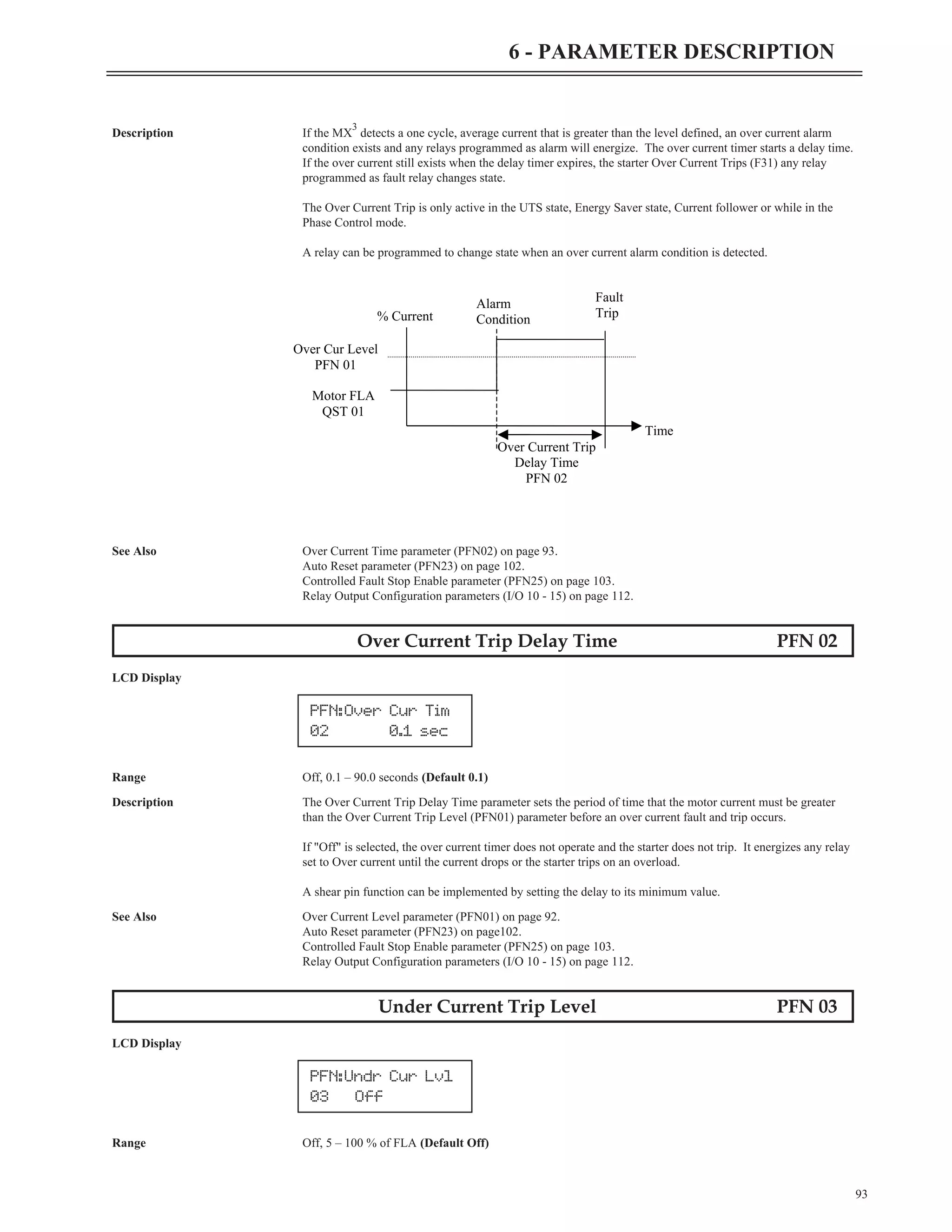
Over Current Trip Level PFN 01
LCD Display
Range Off, 50 – 800 % of FLA (Default Off)
PFN:Over Cur Lvl
01 Off
PFN: Jump Code
00 1
CFN:SSpd Kick T
27 1.0sec](https://image.slidesharecdn.com/01-890034-02-00-lv-mx3-user-manual-1-210614135928/75/01-890034-02-00-lv-mx3-user-manual-1-100-2048.jpg)
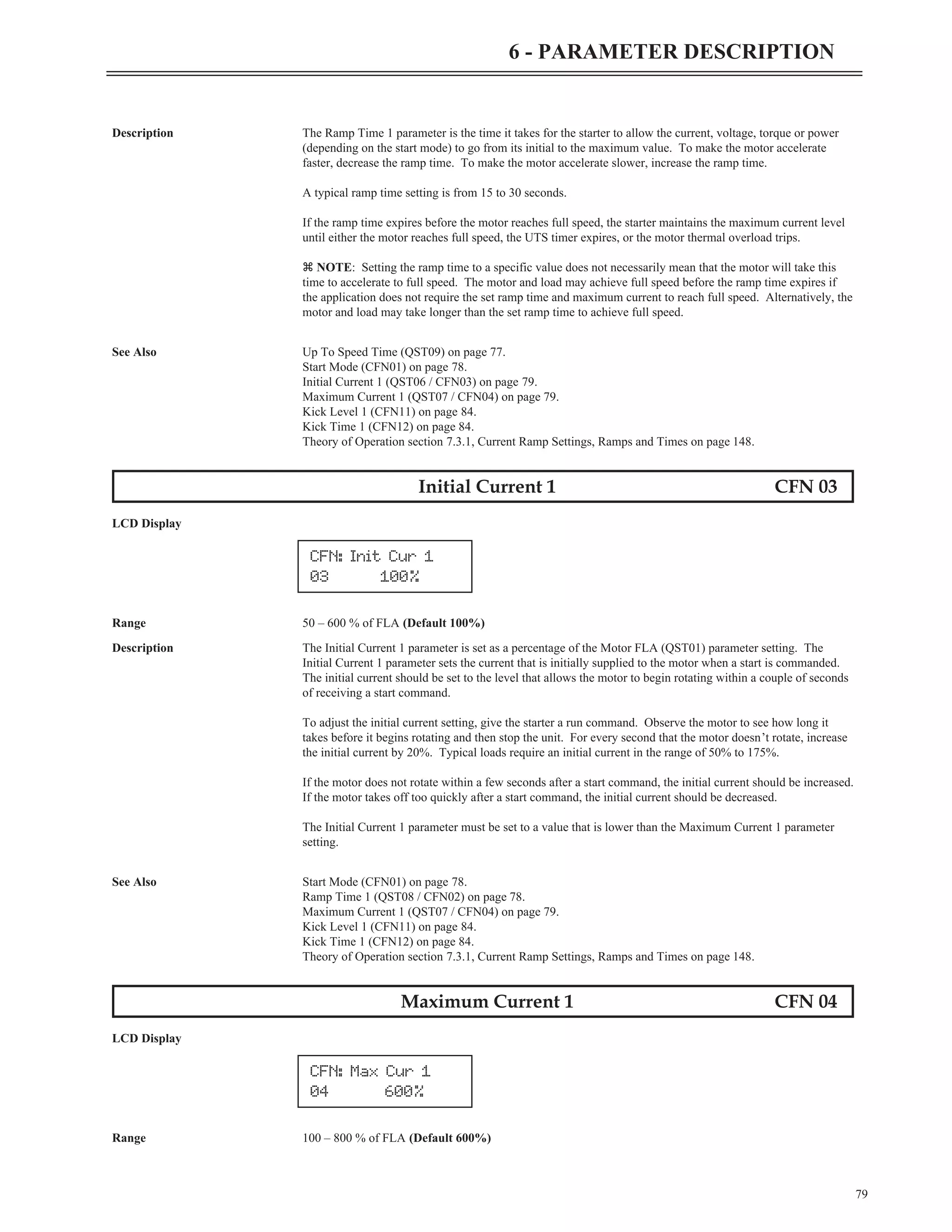
![110
6 - PARAMETER DESCRIPTION
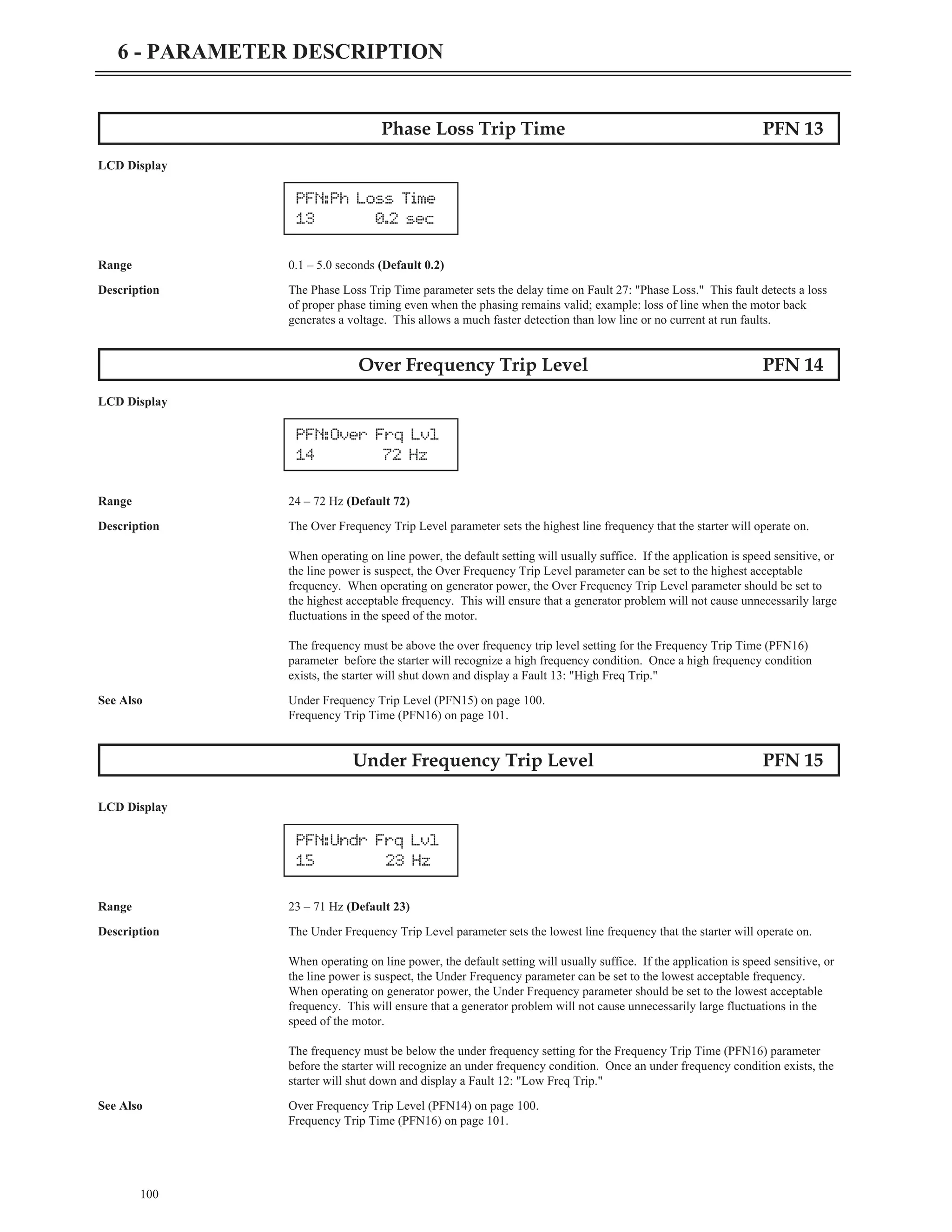
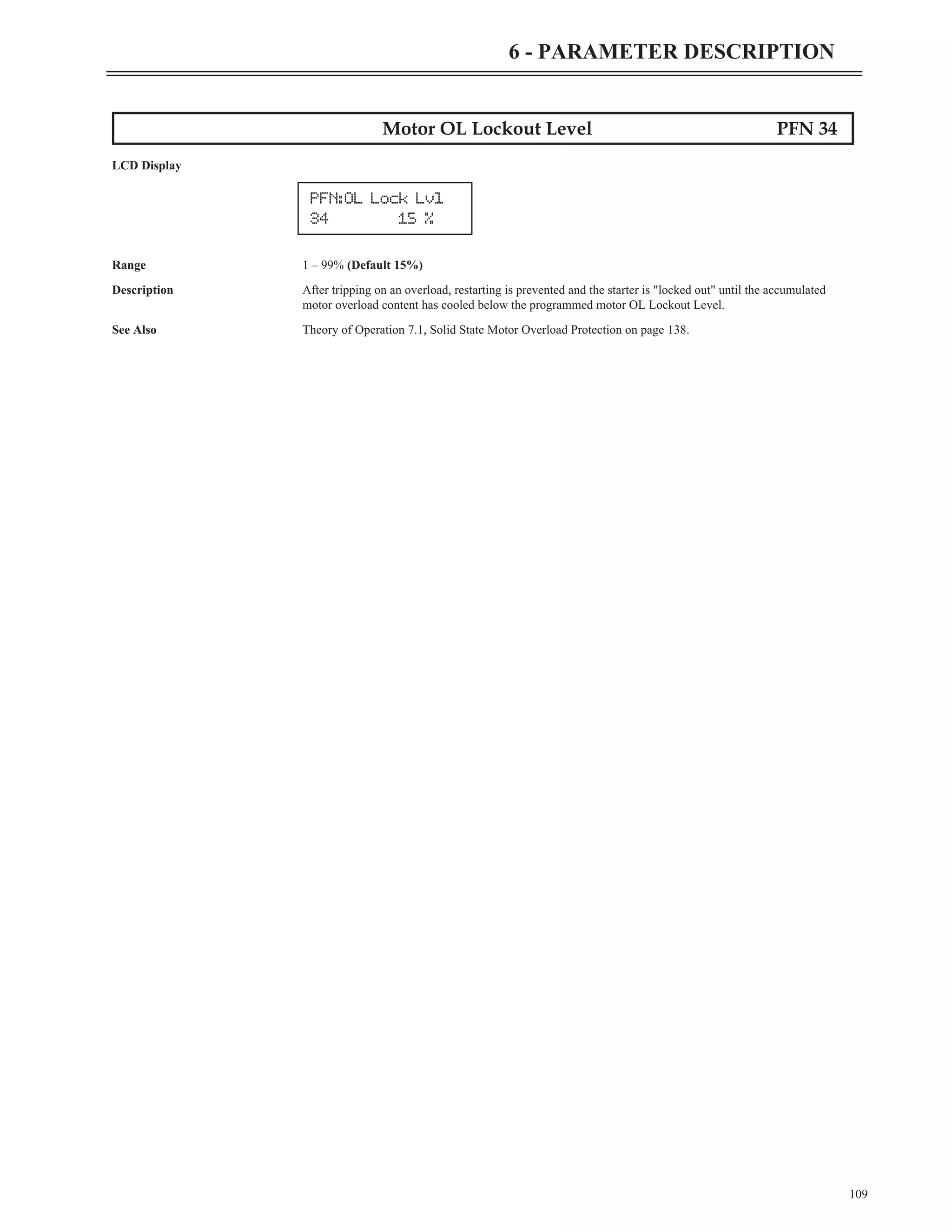
Motor OL Auto Lockout Level PFN 35
LCD Display
Range Off, Auto (Default Off)
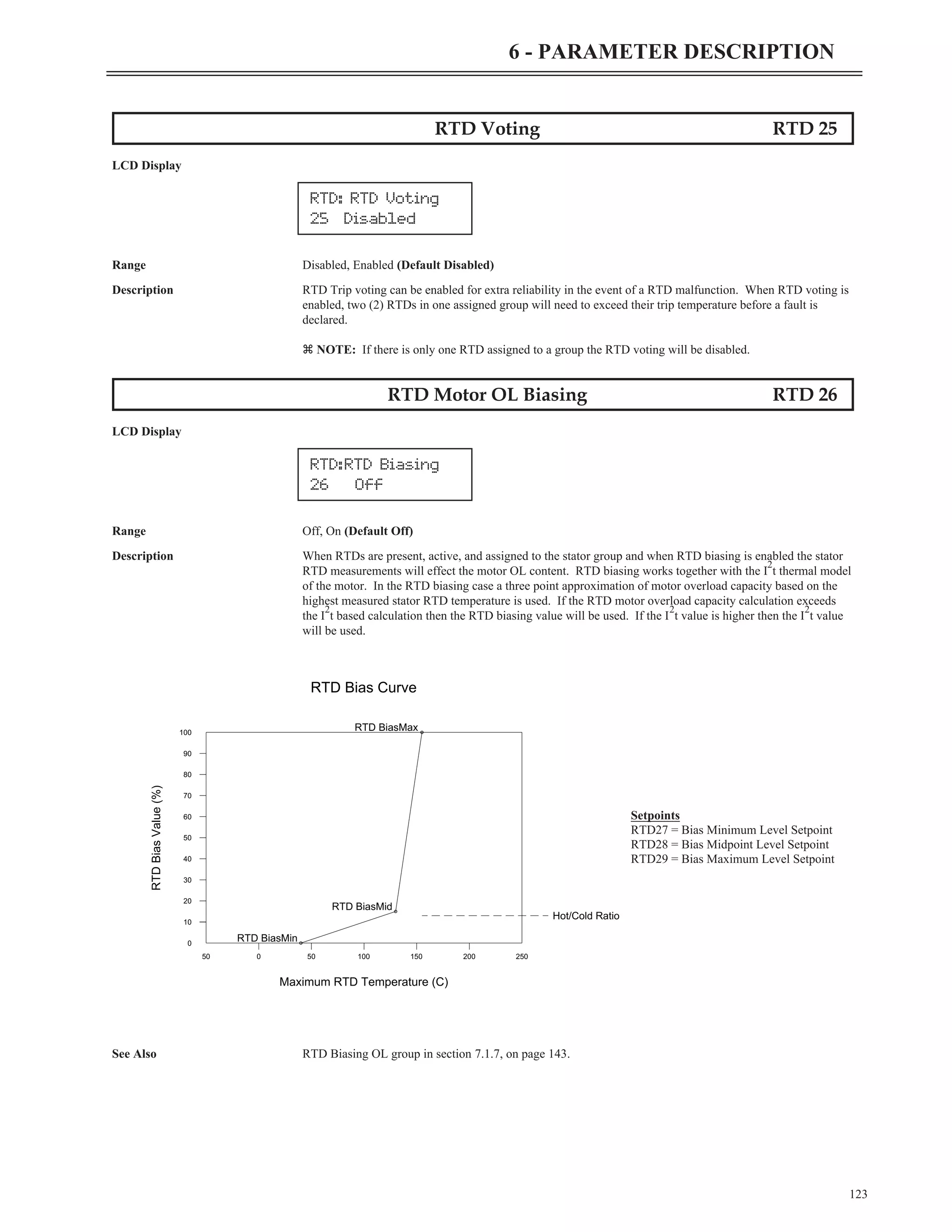
Description The MX
3
has the capability to automatically calculate a motor OL lockout release level. This level shall be
calculated so that the OL lockout is cleared when there is enough OL content available to start the motor
without tripping the OL. This prevents the motor from being started if the O/L will trip during the start.
The value shall be calculated based on OL content used for the past four (4) successful motor starts. A factor
of 1.25 shall be applied as a safety margin.
Example:
The OL content used for the past 4 starts were 30%, 29%, 30%, 27%
Average OL content used is 29% (using integer math).
Multiply result by 1.25 -> 36%
The new calculated motor OL lockout release level will be 100% - 36% -> 64%
The starting OL% content shall be latched when a start command is given. A value for OL content used
during a start shall only be added to the list if the motor start fully completes the start (i.e. the starter reaches
up to speed).
z NOTE: This feature should not be used on systems where the starting load varies greatly from start to
start.
z NOTE: The OL does not have to reach 100% for the lockout to occur.
See Also Motor OL Lockout Level (PFN34) on page 109.
Theory of Operation 7.1, Solid State Motor Overload Protection on page 138.
Jump to Parameter I/O 00
LCD Display
Description By changing the value of this parameter and pressing [ENTER], you can jump directly to any parameter
within the group.
PFN:OL Lock Calc
35 Off
I/O: Jump Code
00 1](https://image.slidesharecdn.com/01-890034-02-00-lv-mx3-user-manual-1-210614135928/75/01-890034-02-00-lv-mx3-user-manual-1-118-2048.jpg)
![See Also Digital Input Configuration parameters (I/O 01-08) on page 111.
Theory of Operation section 7.8, Wye-Delta Operation on page 168.
Keypad Stop Disable I/O 26
LCD Display
LCD Description
Range Disabled Keypad Stop does not stop the starter.
Enabled Keypad Stop does stop the starter. (Default)
Description If “Disabled”
When this parameter is set to "Disabled", the keypad [STOP] button is de-activated. This should be done with
caution, as the [STOP] will not stop the starter.
If the keypad is selected as local or remote control sources, the [STOP] key cannot be disabled.
If “Enabled”
When this parameter is set to "Enabled", the keypad stop button is enabled and stops the starter regardless of
the selected control source (keypad, terminal or serial).
See Also Local Source parameter (QST04) on page 74.
Remote Source parameter (QST05) on page 74.
Auto Start Selection I/O 27
LCD Display
LCD Description
Range Disabled When Disabled, the Start input must always transition from low to high
for a start to occur. (Default)
Power When set to Power, a start will occur if the Start input is high while
control power is applied.
Fault When set to Fault, a start will occur if the Start input is high when a
fault is reset.
Power, Fault When set to Power and Fault, a start will occur if the Start input is
high while control power is applied, and a start will occur if the Start
input is high when a fault is reset.
Description The Auto Start Selection parameter determines whether or not a transition from low to high is required on the
Start input for a start to occur after either a power up or a fault reset. This applies to lockout conditions being
cleared as well. The behavior for a lockout clearing is the same as for a fault being reset.
119
6 - PARAMETER DESCRIPTION
I/O:Keypad Stop
26 Enabled
I/O: Auto Start
27 Disabled](https://image.slidesharecdn.com/01-890034-02-00-lv-mx3-user-manual-1-210614135928/75/01-890034-02-00-lv-mx3-user-manual-1-127-2048.jpg)
![120
6 - PARAMETER DESCRIPTION
Jump to Parameter RTD 00
LCD Display
Description By changing the value of this parameter and pressing [ENTER], you can jump directly to any parameter
within the group.
RTD Module #1 Address RTD 01
LCD Display
Range Off, 16 to 23 (Default Off)
Description The module #1 address parameter has to be set to the Modbus address of the first RTD module attached to the
soft-starter. The address of the RTD module can be verified by checking the rotary switch on the top of the
RTD module.
RTD Module #2 Address RTD 02
LCD Display
Range Off, 16 to 23 (Default Off)
Description The module #2 address parameter has to be set to the Modbus address of the second RTD module attached to
the soft-starter. The address of the RTD module can be verified by checking the rotary switch on the top of
the RTD module. Ensure that module #2 is not set to the same address as module #1.
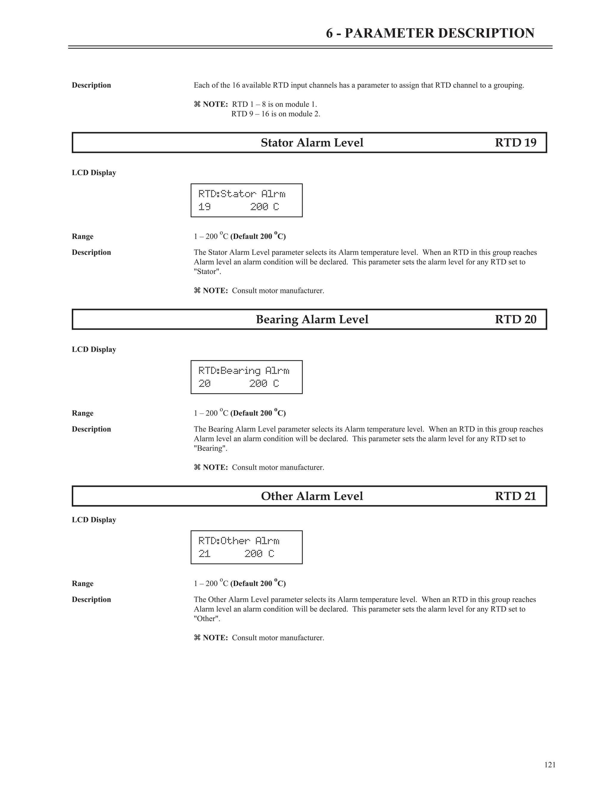
RTD Group RTD 03 - RTD 18
LCD Display
(? = RTD number)
(?? = menu index number)
LCD Description
Range Off RTD channel not read.
Stator RTD included in Stator metering group.
Bearing RTD included in Bearing metering group.
Other RTD acts independently.
RTD:RTDMod1 Addr
01 Off
RTD:RTDMod2 Addr
02 Off
RTD:RTD 1 Group
03 Off
RTD:RTD ? Group
?? Off
RTD: Jump Code
00 1](https://image.slidesharecdn.com/01-890034-02-00-lv-mx3-user-manual-1-210614135928/75/01-890034-02-00-lv-mx3-user-manual-1-128-2048.jpg)
![Jump to Parameter FUN 00
LCD Display
Description By changing the value of this parameter and pressing [ENTER], you can jump directly to any parameter
within the group.
Meter FUN 01, 02
LCD Display
LCD Description
Range Ave Current Average current. (Default Meter 1)
L1 Current Current in phase 1.
L2 Current Current in phase 2.
L3 Current Current in phase 3.
Curr Imbal Current Imbalance %.
Ground Fault Residual Ground Fault % FLA.
Ave Volts Average Voltage L-L RMS. (Default Meter 2)
L1-L2 Volts Voltage in, L1 to L2 RMS.
L2-L3 Volts Voltage in, L2 to L3 RMS.
L3-L1 Volts Voltage in, L3 to L1 RMS.
Overload Thermal overload in %.
Power Factor Motor power factor.
Watts Motor real power consumed.
VA Motor apparent power consumed.
vars Motor reactive power consumed.
kW hours Kilo-watt-hour used by the motor, wraps at 1,000.
MW hours Mega-watt-hour used by the motor, wraps at 10,000.
Phase Order Phase Rotation.
Line Freq Line Frequency.
Analog In Analog Input %.
Analog Out Analog Output %.
Run Days Running time in days, wraps at 2,730 days.
Run Hours Running time in Hours and Minutes, wraps at 24:00.
Starts Number of Starts, wraps at 65,536.
TruTorque % TruTorque %.
Power % Power %.
Pk accel Curr Peak starting current.
Last Start T Last starting duration.
Zero Seq GF Zero sequence ground fault.
Stator Temp Highest Stator temperature.
Bearing Temp Highest Bearing temperature.
Other Temp Highest Other temperature.
All Temp Highest of all temperatures.
Description Parameters FUN 01 and FUN 02 configure which meters are displayed on the two lines of the main display
screen.
125
6 - PARAMETER DESCRIPTION
FUN: Meter 2
02 Ave Volts
FUN: Meter 1
01 AveCurrent
FUN: Jump Code
00 1](https://image.slidesharecdn.com/01-890034-02-00-lv-mx3-user-manual-1-210614135928/75/01-890034-02-00-lv-mx3-user-manual-1-133-2048.jpg)
![See Also Over Voltage Level parameter (PFN10) on page 98.
Under Voltage Level parameter (PFN11) on page 99.
Voltage Trip Time parameter (PFN12) on page 99.
Meter parameter (FUN01, FUN02) on page 125.
Motor Rated Power Factor FUN 06
LCD Display
Range -0.01 lag – 1.00 unity (Default –0.92)
Description The Motor Rated Power Factor parameter sets the motor power factor value that is used by the MX
3
starter for
TruTorque and Power control calculations and metering calculations.
If TruTorque or Power acceleration and/or deceleration control is used, it is very important to properly set this
parameter to the motor's full load rated power factor (usually available on the motor nameplate or from the
motor manufacturer). For a typical induction motor, this value is between 0.80 and 0.95.
If the motor rated power factor is not available from either the motor nameplate or the motor manufacturer, the
value can be obtained by viewing the power factor meter.
With the motor running at full name plate current, view the power factor meter by pressing the [UP] arrow key
until the Motor PF meter is displayed using the LCD display.
The meter value can be entered into the Rated Power Factor parameter.
See Also Meter parameters (FUN01, FUN02) on page 125.
Theory of Operation section 7.3.3, TruTorque Acceleration Control Settings and Times on page 149.
Theory of Operation section 7.3.4, Power Control Acceleration Settings and Times on page 151.
127
6 - PARAMETER DESCRIPTION
FUN: Motor PF
06 -0.92](https://image.slidesharecdn.com/01-890034-02-00-lv-mx3-user-manual-1-210614135928/75/01-890034-02-00-lv-mx3-user-manual-1-135-2048.jpg)
![Passcode FUN 26
LCD Display
Description The MX
3
provides a means of locking parameter values so that they may not be changed. Once locked, the
parameters values may be viewed on the display, but any attempt to change their values by pressing the [UP]
or [DOWN] keys is ignored.
Viewing the Passcode parameter indicates whether or not the parameters are locked. If they are locked, the
Passcode parameter displays "On". If they are not locked, the Passcode parameter displays "Off".
To lock the parameters, press the [ENTER] key while viewing the Passcode parameter. This allows entry of a
4-digit number. Press the [UP] or [DOWN] keys and [ENTER] for each of the four digits. After entering the
fourth digit, the number is stored as the passcode and the parameters are locked.
Once parameters are locked, the same 4-digit number must be re-entered into the Passcode parameter in order
to unlock them. Any other 4-digit number entered will be ignored.
z NOTE: To re-establish password protection after it has been cleared, the password must be entered again.
Fault Log FL1 - 9
LCD Display
Range FL1 – FL9
Description When a fault occurs, the fault number is logged in non-volatile memory. The most recent fault is in FL1 and
the oldest fault is in FL9.
Pressing [ENTER] toggles through the Starter data recorded at the time of the fault. See section 4.4.5 for
more information.
See Also Appendix C - Fault Codes on page 205.
Event Recorder E01 - E99
Range E01 – E99
Description An event is anything that changes the present state of the starter. Some examples of events would be an
operation fault, a Start command, or a Stop command. The event recorder stores the last 99 events. When an
event occurs, the event number is logged in non-volatile memory. The most recent event is in E01 and the
oldest event is in E99.
See Also Appendix A – Event Codes on page 202.
Appendix C – Fault Codes on page 205.
135
6 - PARAMETER DESCRIPTION
FL1: Last Fault #
Fault Name
FUN: Passcode
26 Off](https://image.slidesharecdn.com/01-890034-02-00-lv-mx3-user-manual-1-210614135928/75/01-890034-02-00-lv-mx3-user-manual-1-143-2048.jpg)
![LCD Display The first screen displayed in the event recorder gives the starter state on the second line of the screen. See
below;
Pressing [ENTER] will now display the starter state at the time of the event on the bottom line of the screen.
See below;
Pressing [ENTER] for a 2nd time will display the time of the event on the bottom line of the screen. See
below;
Pressing [ENTER] for a 3rd time will display the date of the event on the bottom line of the screen. See
below;
Pressing [ENTER] again returns to the first display screen.
See Also Appendix A - Event Codes on Page 202.
136
6 - PARAMETER DESCRIPTION
E01: Event #??
hh:mm:ss
E01: Event #??
mm/dd/yy
E01: Event #??
Stop Complete
E01: Event #??
Fault](https://image.slidesharecdn.com/01-890034-02-00-lv-mx3-user-manual-1-210614135928/75/01-890034-02-00-lv-mx3-user-manual-1-144-2048.jpg)
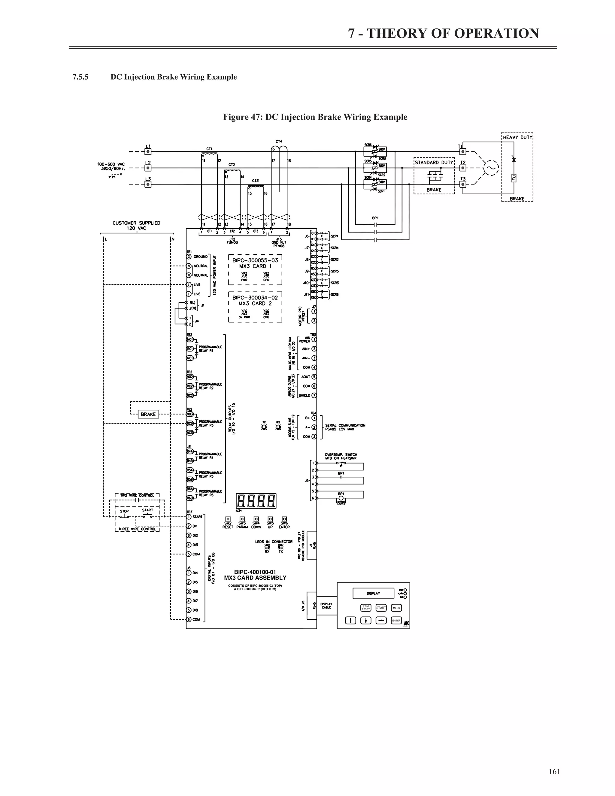
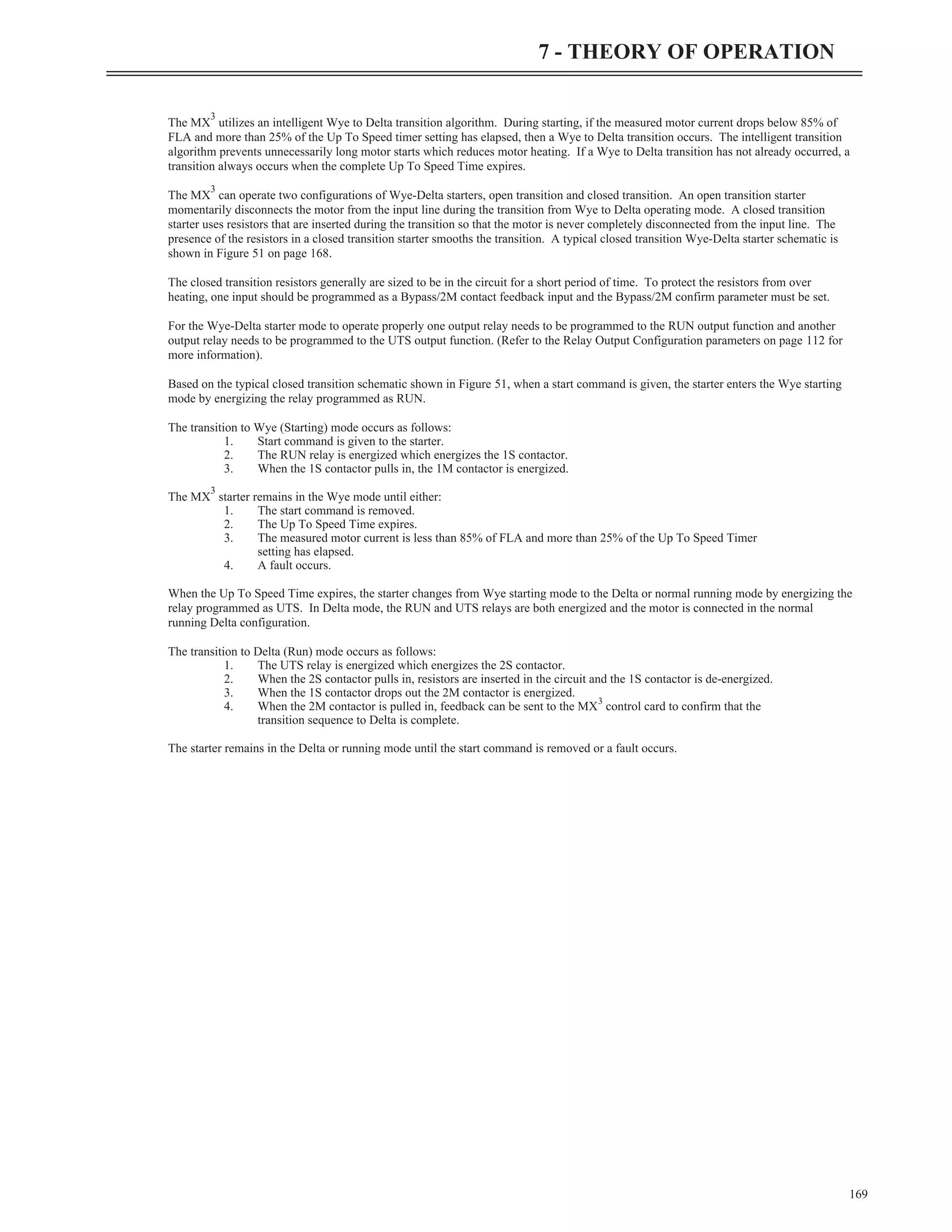
![If the motor manufacturer does not specify the motor cooling time, the following approximations for standard TEFC cast iron motors
based on frame size can be used:
For motors less than 300hp, another approximation based on allowable motor starts per hour can also be used to set an initial value of the
Motor Overload Cooling Time (PFN32) parameter:
z NOTE: The Motor Overload Cooling Time (PFN32) parameter is defined as the time that it takes for the motor to cool from 100%
overload content to less than 1% overload content. Sometimes a motor manufacturer may provide a cooling time constant (t or tau)
value. In these cases, the Motor Overload Cooling Time (PFN32) parameter should be set to five (5) times the specified time constant
value.
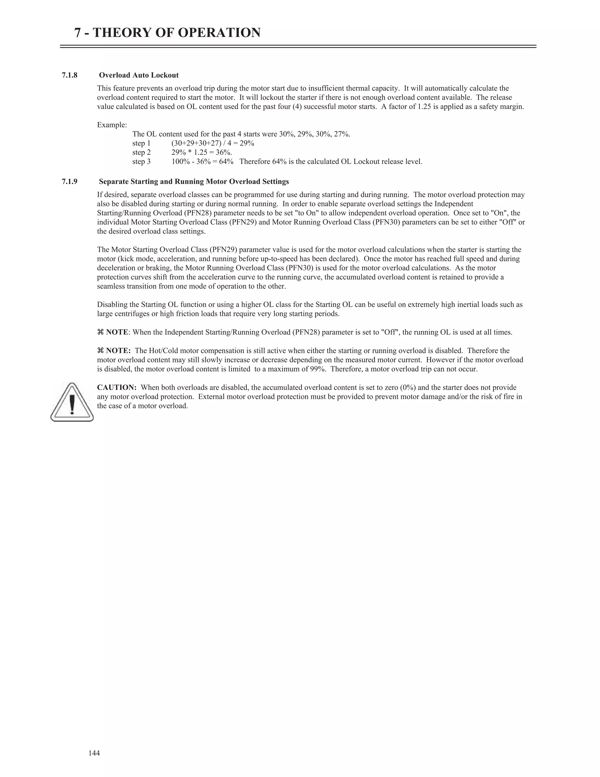
7.1.11 Motor Cooling While Running
When the motor is running, the Motor Overload Cooling Time (PFN32) parameter and the Motor Overload Hot/Cold Ratio (PFN31)
parameter settings control the motor OL content. If the motor overload content is above the steady state OL running level (See section
7.1.6, Hot / Cold Motor Overload Compensation for more details) the motor OL exponentially cools to the appropriate steady state OL
level. When the motor is running, the cooling time is adjusted based on the measured current level and current imbalance level at which
the motor is operating.
In all cases, the running motor cooling time is shorter (motor will cool faster) than when the motor is stopped. The faster cooling results
because it is assumed that when a motor is running, cooling air is being applied to the motor.
7.1.12 Emergency Motor Overload Reset
The MX
3
has an emergency motor overload reset feature that allows the user to override the overload starter lockout. This resets the
motor overload content to 0%. It does not reset the overload fault.
To perform an emergency overload reset, simultaneously press the [RESET] and [DOWN] buttons on the keypad. An emergency
overload reset may also be performed by applying 120 Volts to a digital input that is configured as an emergency overload reset input or
by setting the emergency overload reset bit in the starter control Modbus register.
CAUTION: This feature should only be used in an emergency. Before an emergency reset is performed the cause of the motor overload
should be investigated to ensure that the motor is capable of restarting without causing undesired motor or load damage. When the
emergency motor overload reset is used, the accumulated motor overload content is reset back to zero (0%). Therefore, the MX
3
motor
protection functions may not be able to fully protect the motor from damage during a restart after performing an emergency motor
overload reset.
146
7 - THEORY OF OPERATION
Frame Size Cooling Time
180 30 min
280 60 min
360 90 min
400/440 120 min
500 180 min
Larger frames
Consult
Manufacturer
hour
per
Starts
minutes
60
(minutes)
Time
Cooling
Motor »
Factor
Derate
Imbalance
Current
1
*
FLA
Motor
Current
Running
Measured
*
Stopped
Time
Cooling
Running
Time
Cooling =](https://image.slidesharecdn.com/01-890034-02-00-lv-mx3-user-manual-1-210614135928/75/01-890034-02-00-lv-mx3-user-manual-1-154-2048.jpg)


![SCR Testing
8.5 SCR Testing
8.5.1 Resistance
The SCRs in the starter can be checked with a standard ohmmeter to determine their condition.
Remove power from the starter before performing these checks.
Ÿ Check from L to T on each phase. The resistance should be over 50k ohms.
Ÿ Check between the gate leads for each SCR (red and white twisted pair).
The resistance should be from 8 to 50 ohms.
z NOTE: The resistance measurements may not be within these values and the SCR may still be good. The checks are to determine if
an SCR is shorted "L" to "T" of if the gate in an SCR is shorted or open. An SCR could also still be damaged even though the
measurements are within the above specifications.
8.5.2 Voltage
When the starter is running, the operation of the SCRs can be confirmed with a voltmeter.
Extreme caution must be observed while performing these checks since the starter has lethal voltages applied while operating.
While the starter is running and up to speed, use an AC voltmeter, check the voltage from "L" to "T" of each phase. The voltage should
be less than 1.5 Volts. If the starter has a bypass contactor, the voltage drop should be less than 0.3 volts.
Using a DC voltmeter, check between the gate leads for each SCR (red and white twisted pair). The voltage should between 0.5 and 2.0
volts.
8.5.3 Integral Bypass (RB3)
A voltage check from "L" to "T" of each phase of the RediStart starter should be preformed every 6 months to confirm the bypass
contactors are operating correctly.
Extreme caution must be observed while performing these checks since the starter has lethal voltages applied while operating.
While the starter is running and Up to Speed, use an AC voltmeter; check the voltage from "L" to "T" of each phase. The voltage drop
across the contactor contacts should be less than 300mV. The bypass should be serviced if the voltage drop is greater that 300mV. It
may be necessary to clean the contact tips or replace the contactor.
Built-In Self Test Functions
8.6 Built In Self Test Functions
The MX
3
has two built in self test (BIST) modes. The first test is the standard self test and is used to test many of the basic functions of
the starter without line voltage being applied. The second test is a line powered test that is used to verify the current transformer’s
locations and connections and to test for shorted SCRs/power poles, open or non-firing SCRs/power poles, and ground fault conditions.
8.6.1 Standard BIST Tests
(FUN 22 - Std BIST):
The standard BIST tests are designed to be run with no line voltage applied to the starter. In selected low voltage systems where a
disconnect switch is used, the Disconnect Switch must be opened before starting the standard tests. Standard BIST mode can be entered
by entering the appropriate value into the Miscellaneous Command (FUN22) user parameter.
CAUTION: In order to prevent backfeeding of voltage through the control power transformer (if used), control power must be carefully
applied to the MX
3
control card and contactors so that self testing can occur safely. In low voltage applications, the user must verify that
the applied test control power cannot be fed backwards through the system. “Run/Test” isolation switches, test power plugs, and wiring
diagrams are available from Benshaw.
CAUTION: In low voltage systems with an inline/isolation contactor. Before the inline test is performed verify that no line voltage is
applied to the line side of the inline contactor. Otherwise when the inline test is performed the inline contactor will be energized,
applying line voltage to the starter, and a BIST test fault will occur.
The standard BIST tests comprise of:
Step 1 LCD Display
Go to parameter (FUN22) - misc commands and press [ENTER].
Press [UP] button until it reads "Std BIST" and press [ENTER].
195
8 - TROUBLESHOOTING & MAINTENANCE](https://image.slidesharecdn.com/01-890034-02-00-lv-mx3-user-manual-1-210614135928/75/01-890034-02-00-lv-mx3-user-manual-1-203-2048.jpg)
![Std BIST test will commence.
z NOTE: Designed to run with no line voltage applied.
Step 2– RUN relay test and Inline Feedback Test:
In this test, the RUN assigned relays are cycled on and off once and the feedback from an inline contactor is verified. In order to have a
valid inline contactor feedback, a digital input needs to be set to Inline Confirm and the input needs to be wired to an auxiliary contact
of the inline contactor. The feedback is checked in both the open and closed state. If the feedback does not match the state of the RUN
relay within the amount of time set by the Inline Config (I/O24) parameter an “Inline” fault will occur.
z NOTE: If no digital input is assigned as an Inline Confirm input this test will always pass.
z NOTE: If the Inline Config (I/O24) parameter on page 118 is set to "Off" this test will be skipped.
Step 3 – UTS relay test and Bypass Feedback Test:
In this test, the dedicated bypass relay (if assigned) and UTS assigned relays are cycled on and off once and the feedback from a bypass
contactor is verified. In order to have a valid bypass contactor feedback, the dedicated bypass confirm input and any other inputs set to
bypass confirm needs to be wired to an auxiliary contact of the bypass contactor. The feedback is checked in both the open and closed
state. If the feedback does not match the state of the UTS relay within the amount of time set by the Bypass Feedback (I/O25)
parameter a “Bypass/2M Fault” will occur.
z NOTE: If the dedicated bypass relay is set to "fan" and if no digital input are assigned as a Bypass Confirm input this test will
always pass.
Step 4 – Sequential SCR gate firing (L1+, L1-, L2+, L2-, L3+, L3-):
In this test the SCR gate outputs are sequentially fired starting with the L1+ device(s) and ending with the L3- device(s). This test can
be used to verify that the SCR gate leads are connected properly. The gate voltage can be verified using a DC voltage meter or
oscilloscope. The voltage on each red and white wire pair should be between 0.5VDC and 2.0VDC.
This test will check all 6 gates separately. The order the BIST will check the gates is as follows: Gate 6, Gate 3, Gate 5, Gate 2, Gate 4,
Gate 1. The question mark (?) in the display below refers to which gate is being fired up.
Step 5 – Simultaneous SCR gate firing:
In this test the SCR gate outputs are simultaneously fired (all gates on). This test can be used to verify that the SCR gate leads are
connected properly. The gate voltage can be verified using a DC voltage meter or oscilloscope. The voltage on each red and white wire
pair should be between 0.5VDC and 2.0VDC.
Pressing [ENTER] on the keypad at any time will abort the current test in progress and proceed to the next BIST test.
During the standard BIST tests if line voltage or phase current is detected, the MX
3
will immediately exit BIST mode and declare a
“BIST Abnormal Exit” fault.
196
8 - TROUBLESHOOTING & MAINTENANCE
BIST Mode
Inline Closed
BIST Mode
Inline Open
BIST Mode
Bypass Closed
BIST Mode
Bypass Open
BIST Mode
Gate ? on
BIST Mode
All Gates on
FUN: Misc commands
22 Std BIST](https://image.slidesharecdn.com/01-890034-02-00-lv-mx3-user-manual-1-210614135928/75/01-890034-02-00-lv-mx3-user-manual-1-204-2048.jpg)
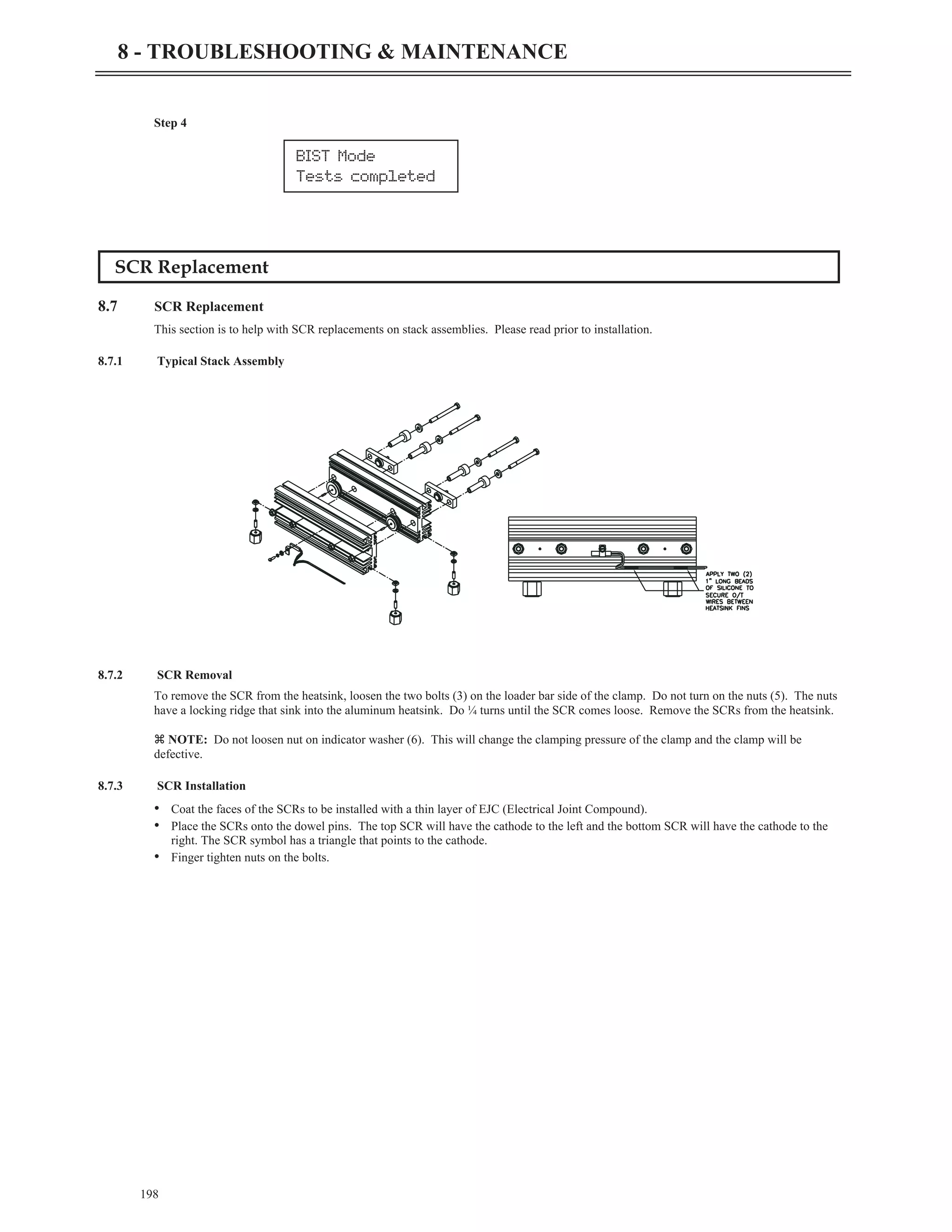
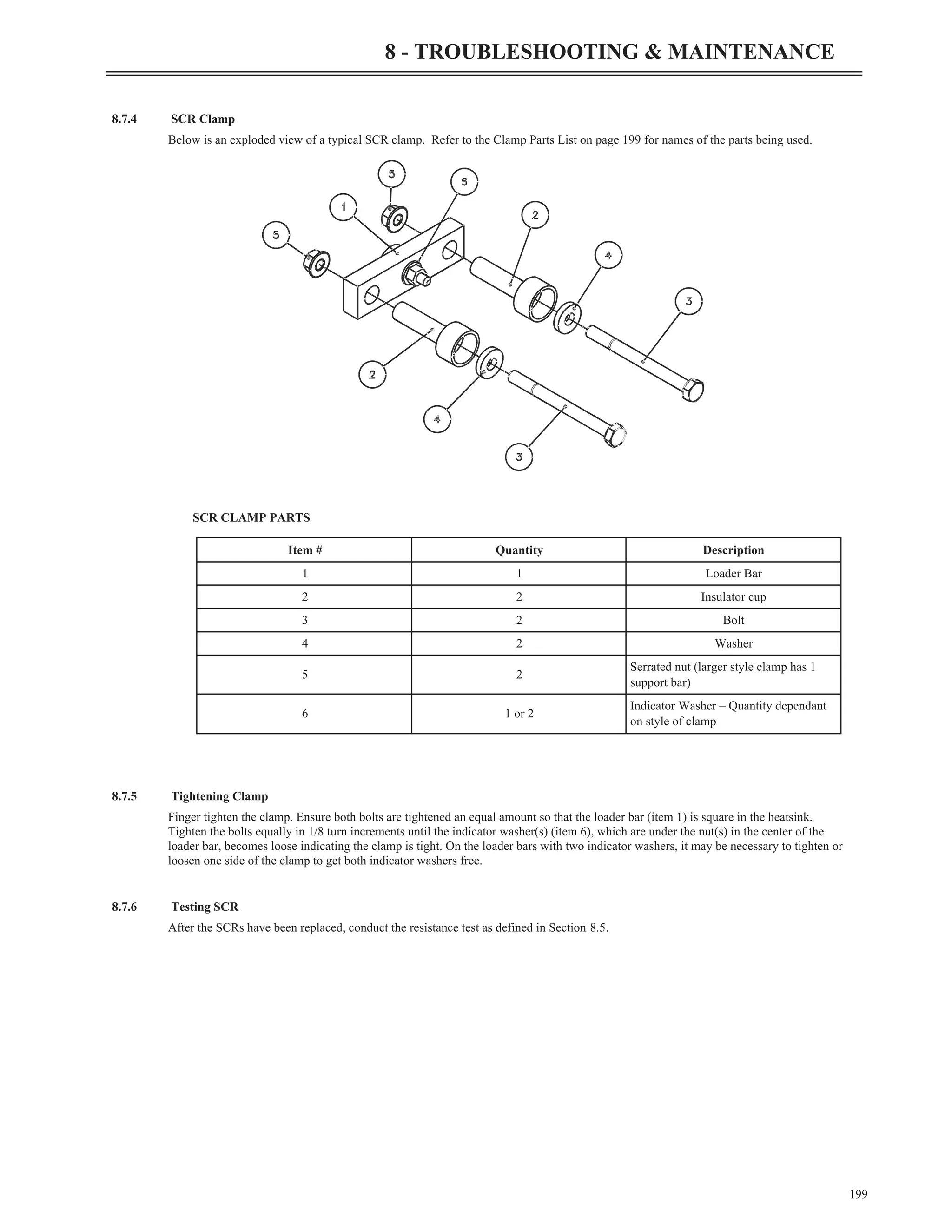
![Step 6
8.6.2 Powered BIST Tests
(FUN 22 - Powered BIST):
The powered BIST tests are designed to be run with normal line voltage applied to the starter and a motor connected. Powered BIST
verifies that the power poles are good, no ground faults exist, CTs are connected and positioned correctly and that the motor is
connected. Powered BIST mode can be entered by entering the appropriate value into the Miscellaneous Command (FUN22) user
parameter.
z NOTE: The powered BIST test is only for use with SCR based reduced voltage soft starters. Powered BIST can not be used with
wye-delta or ATL types of starters.
z NOTE: The motor wiring MUST be fully connected before starting the powered BIST tests. Also the motor must be at rest
(stopped). Otherwise the powered BIST tests will not function correctly.
z NOTE: Before using the powered BIST test function, the following MX
3
user parameters MUST be set for correct operation of the
powered BIST test: Motor FLA (QST01), CT Ratio (FUN03), Phase Order (FUN04), Rated Voltage (FUN05), and Starter Type
(FUN07).
The powered BIST tests comprise of:
Step 1 LCD Display
Go to FUN22- misc commands and press [ENTER].
Increment up to "Powered BIST" and press [ENTER].
Powered BIST test will commence.
Step 2– Shorted SCR and Ground Fault Test:
In this test each power pole is energized individually. If current flow is detected, the MX
3
controller attempts to differentiate whether it
is a shorted SCR/shorted power pole condition or a ground fault condition and either a “Bad SCR Fault” or “Ground Fault” will occur.
Step 3– Open SCR and Current Transformer (CT) Test
In this test, a low-level closed-loop controlled current is selectively applied to various motor phases to verify that the motor is connected,
all SCRs are turning on properly, and that the CTs are wired and positioned properly. If current is detected on the wrong phase then a
“BIST CT Fault” fault will be declared. If an open motor lead, open SCR, or non-firing SCR is detected then a “Bad SCR Fault” will
occur.
z NOTE: When this test is in progress audible humming or buzzing maybe heard from the motor.
Pressing [ENTER] on the keypad at any time will abort the current test in progress and proceed to the next BIST test.
z NOTE: If line voltage is lost during the powered tests a “BIST Abnormal Exit” fault will occur.
z NOTE: The powered BIST tests will verify that the input phase order is correct. If the measured phase order is not the same as the
Phase Order (FUN04) parameter a phase order fault will occur.
197
8 - TROUBLESHOOTING & MAINTENANCE
BIST Mode
Tests completed
FUN: Misc commands
22 Powered BIST
BIST Mode
Shorted SCR/GF
BIST Mode
Open SCR/CTs](https://image.slidesharecdn.com/01-890034-02-00-lv-mx3-user-manual-1-210614135928/75/01-890034-02-00-lv-mx3-user-manual-1-205-2048.jpg)