Downloaded 30 times

![automatic white balance adjustment function You can assign the desired functions to these
does not operate. switches on OPERATION >Assignable SW in
Chapter 1 Overview
BLACK: Adjust the black set and black balance the setup menu (see page 136).
automatically. EZ Mode is assigned to the ASSIGN. 1 switch,
You can use the AUTO W/B BAL switch even and Off is assigned to the ASSIGN. 2/3 switches
when the ATW (Auto Tracing White Balance) as the factory default setting.
function is operating. The ASSIGN.1/3 switches are provided with an
If you push the switch to the WHITE side once indicator to show whether a function is assigned
more during the automatic white balance to the switch (ON) or not (OFF).
adjustment, the adjustment is cancelled and the
white balance setting returns to the original b COLOR TEMP. (color temperature)
setting. button
If you push the switch to the BLACK side once Press to light the button and change the color
more during the automatic black balance temperature for shooting (factory default setting).
adjustment, the adjustment is cancelled and the You can use this as an assignable switch (see
black balance setting returns to the original page 136).
setting.
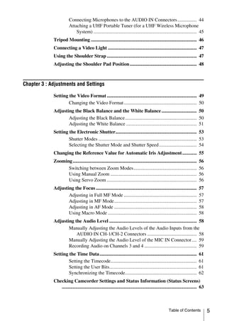
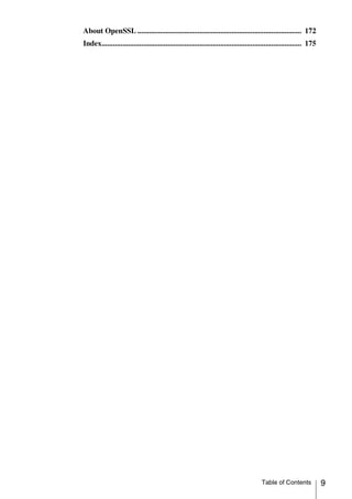
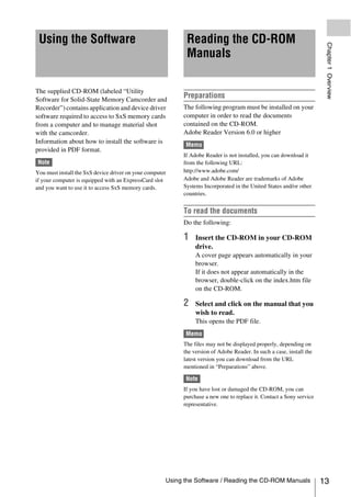
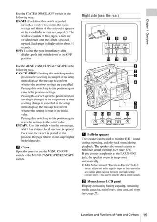
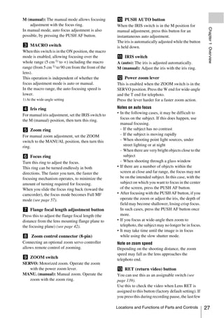
c ALARM (alarm tone volume
f MIC (microphone) LEVEL control adjustment) knob
Adjusts the input level of audio channels 1, 2, 3 Controls the volume of the warning tone that is
and 4 (see page 58). output via the built-in speaker or optional
earphones. When the knob is turned to the
Right side (near the front) minimum position, no sound can be heard.
However, if MAINTENANCE >Audio >Min
Alarm Volume in the setup menu is set to [Set],
the alarm tone is audible even when this volume
control is at the minimum position.
ALARM
Minimum Maximum
d MONITOR (monitor volume
adjustment) knob
Controls the volume of the sound other than the
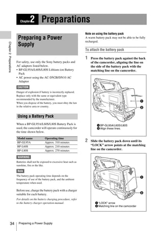
warning tone that is output via the built-in speaker
or earphones. When the knob is turned to the
minimum position, no sound can be heard.
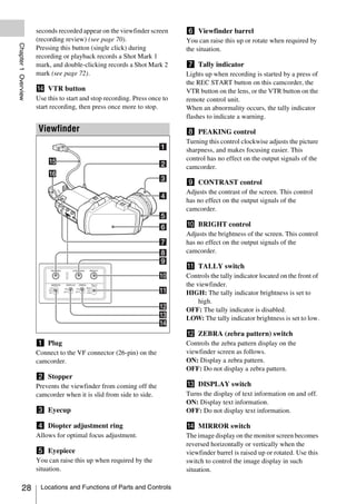
e MONITOR (audio monitor selection)
switches
By means of combinations of the two switches,
you can select audio that you want to hear through
the built-in speaker or earphones.
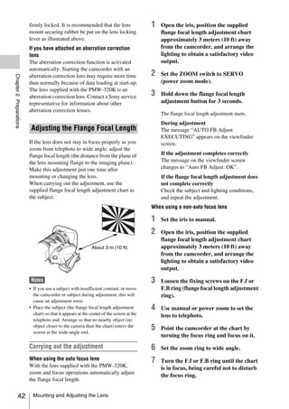
Position of down-side switch: CH-1/2
Position of up-side Audio output
switch
CH-1/CH-3 Channel 1 audio
MIX Channels 1 and 2 mixed
a ASSIGN. (assignable) 1/2/3 switches audio (stereo) a)
Locations and Functions of Parts and Controls 17](https://image.slidesharecdn.com/pmw-320lenk-120216080013-phpapp02/85/Sony-PMW-320K-Operation-Manual-17-320.jpg)
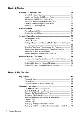
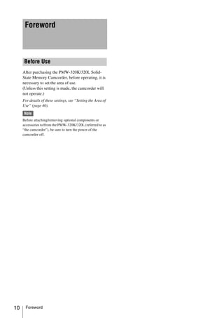
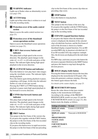
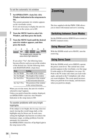
![Position of up-side Audio output • Shooting a subject indoors, against a background
switch through a window
Chapter 1 Overview
• Any high contrast scene
CH-2/CH-4 Channel 2 audio
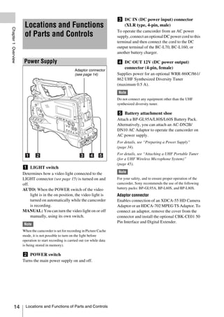
Position of down-side switch: CH-3/4 i WHITE BAL (white balance memory)
Position of up-side Audio output
switch
switch Controls adjustment of the white balance.
CH-1/CH-3 Channel 3 audio PRST: Adjust the color temperature to the preset
MIX Channels 3 and 4 mixed value (the factory default setting: 3200K).
audio (stereo) a) Use this setting when you have no time to
CH-2/CH-4 Channel 4 audio adjust the white balance.
A or B: Recall the white balance adjustment
a) By connecting stereo headphones to the EARPHONE settings already stored in A or B. Push the
jack, you can hear the audio in stereo. (Under AUTO W/B BAL switch (see page 16) on
MAINTENANCE >Audio in the setup menu, the WHITE side, to automatically adjust the
Headphone Out must be set to STEREO.) white balance, and save the adjustment
settings in memory A or memory B.
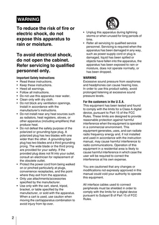
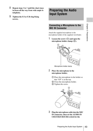
f ASSIGN. (assignable) 0 switch
You can assign the desired function to this switch B (ATW 1)): When this switch is set to B and
on OPERATION >Assignable SW in the setup OPERATION >White Setting >White
menu (see page 137). Switch<B> is set to [ATW] in the setup
Off is assigned to this switch when the camcorder menu, ATW is activated.
is shipped from the factory. You can use the AUTO W/B BAL switch
This is a momentary type switch. Each press of even when ATW is in use.
the switch turns the function assigned to this When this switch is adjusted, the new setting
switch on or off. appears on the viewfinder screen for about three
seconds.
g GAIN selector
1) ATW (Auto Tracing White Balance): The white
Switches the gain of the video amplifier to match balance of the picture being shot is adjusted
the lighting conditions during shooting. The gains automatically for varying lighting conditions.
corresponding to the L, M, and H settings can be
selected on OPERATION >Gain Switch in the j MENU ON/OFF switch
setup menu (see page 106). (The factory settings To use this switch, open the cover.
are L=0 dB, M=6 dB, and H=12 dB.) This switch is used to display the menu on the
When this switch is adjusted, the new setting viewfinder screen or the test signal screen. Each
appears on the viewfinder screen for about three time the switch is pushed down, the menu screen
seconds. is turned on and off.
The function of this switch is the same as that of
h OUTPUT/DCC (output signal/dynamic the MENU button in the thumbnail screen
contrast control) switch operations section.
Switches the video signal output from the camera
module, between the following two. k STATUS ON/SEL/OFF (menu display
BARS: Output the color bar signal. on/page selection/display off) switch
CAM: Output the video signal being shot. When
MENU CANCEL/PRST (preset) /
this is selected, you can switch DCC 1) on and ESCAPE switch
off.
When the menu is not displayed, this switch
1) DCC (Dynamic Contrast Control): Against a very
functions as the STATUS ON/SEL/OFF switch.
bright background with the iris opening adjusted to the
subject, objects in the background will be lost in the
When the menu is displayed, the switch functions
glare. The DCC function will suppress the high as the MENU CANCEL/PRST/ESCAPE switch.
intensity and restore much of the lost detail and is (To use the MENU CANCEL/PRST/ESCAPE
particularly effective in the following cases. switch, open the cover.)
• Shooting people in the shade on a sunny day
18 Locations and Functions of Parts and Controls](https://image.slidesharecdn.com/pmw-320lenk-120216080013-phpapp02/85/Sony-PMW-320K-Operation-Manual-18-320.jpg)
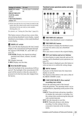
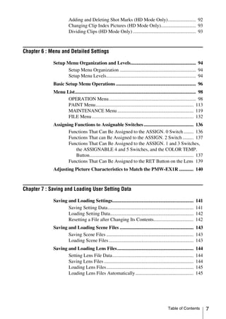
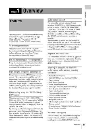
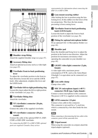
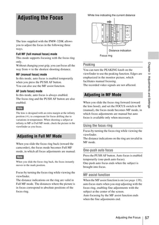
![x2D: The optional digital extender function of Indication Meaning
this camcorder is on. zS&Q REC Recording in progress in Slow &
Chapter 1 Overview
Ex2D: The lens extender and the optional digital Quick Motion mode
extender function of this camcorder are both S&Q STBY Standby in Slow & Quick Motion
on. mode
Digital extender function can be turned on or off zCALL Being called from a connected
by an assignable switch to which Digital Extender device
is assigned. BREVIEW During recording review
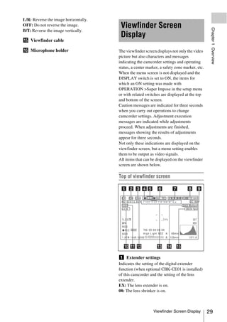
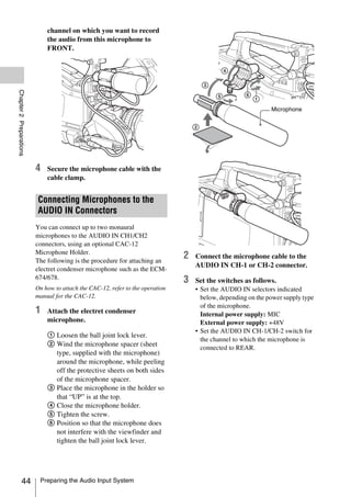
b Zoom position (when the serial lens is g Wireless receiver reception level
mounted) When a wireless receiver is installed in the
Indicates the zoom position of the zoom lens in camcorder, “W” appears together with four
the range from 0 to 99. segment reception level indicators for each of the
channels (1 to 4) that can be used by the receiver.
c Focus position (when the serial lens is The indications are as follows.
mounted) In normal situation: The number of white
Indicates the focus position as distance to the segments indicates the strength of the signal
subject (in units of m). level.
Muting (for an analog receiver) or error rate
d Green tally aggravation (for a digital receiver): The
Lights when the camcorder is the following number of gray segments indicates the
states. strength of the signal level.
• MAINTENANCE >Camera Config >HD-SDI Reception level over peak: “P” is displayed
Remote I/F is set to [G-Tally] in the setup menu instead of the indicators. 1)
and a recording control signal is output from the Tuner battery is low: The channel number and
HD/SD SDI OUT connector. indicator of the corresponding channel
• Green tally signal received (when a camera flash. 1)
adaptor is mounted on the camcorder and a 1) When an optional DWR-S01D is used
camera extension unit is connected)
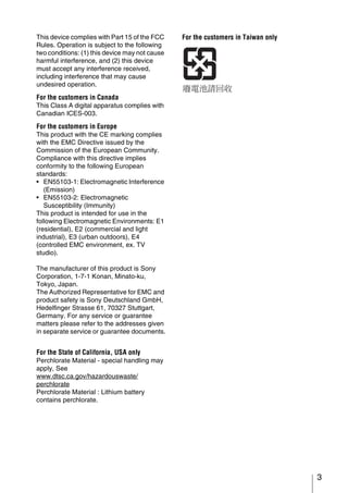
h Battery remaining/voltage capacity
e Media status The following is displayed depending on the type
Displays the name of the currently active media of power source.
slot (A or B).
Type of power What is displayed
f Recording mode/operation status source
Indicates the current recording mode/operation InfoLithium Remaining battery capacity icon
status as follows. battery and remaining recording time
Anton Bauer Remaining battery capacity (%
IndicationMeaning battery indication)
zREC Recording in progress Other type than Input voltage
STBY Standby for recording above
zCACHE Standby in Picture Cache mode
i External power input
zINT REC Recording in progress in Interval
Recording mode Appears when power is supplied from an external
power source connected to the DC IN connector.
zINT STBY Standby for next recording in
Interval Recording mode
j Color temperature
INT STBY Standby in Interval Recording
Displays a color temperature calculated from the
mode
gain of R and B, in the range 1.5 K to 50.0 K (in
zFRM REC Recording in progress in Frame
steps of 0.1 K). The +/– signs may be displayed
Recording mode
depending on the Offset White setting (see
zFRM Standby for next recording in
page 110).
STBY Frame Recording mode
No display: Offset White is OFF
FRM STBY Standby in Frame Recording mode
30 Viewfinder Screen Display](https://image.slidesharecdn.com/pmw-320lenk-120216080013-phpapp02/85/Sony-PMW-320K-Operation-Manual-30-320.jpg)
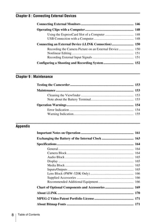
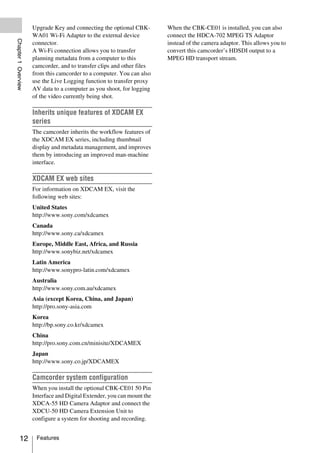
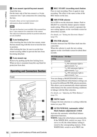
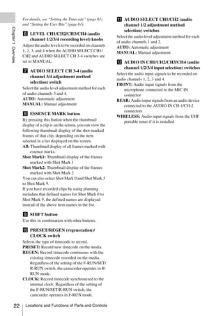
![+: The value of Offset White is greater than
3200K.
Bottom of viewfinder screen
Chapter 1 Overview
–: The value of Offset White is less than 3200K.
k Number of system lines
Indicates the number of system lines (1080/720/
576/480) of video currently being recorded or
played back.
l Video format
Indicates the format of video being currently
played back or recorded (see page 49).
The video aspect ratio (16:9 or 4:3) can also be
displayed when the recording format is set to
DVCAM.
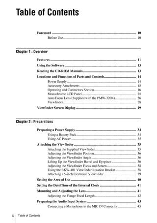
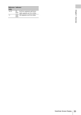
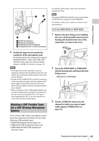
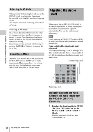
m Depth of field indication (when the a TLCS iris control mode
serial lens is mounted)
The following icons are displayed to indicate the
Error/warning indication video level control modes based on the Total
A bar indicates the depth of field. The display unit Level Control System (TLCS).
is meters or feet, as selected by OPERATION
>Display On/Off >Lens Info in the setup menu. Icon TLCS control mode
An error or warning message is displayed here Backlight mode
depending on the situation.
Standard mode
Under this area, you can also display the name of STD
the next clip to be recorded (see page 112). Spotlight mode
n Special recording mode indication
b Focus adjustment mode (when the auto
The following is displayed when the camcorder is
in a special recording mode. focus lens is mounted)
• Frame Rec (Frame Recording mode) Indicates the current focus adjustment mode of
• Interval Rec (Interval Recording mode) the camcorder.
• S&Q Motion (Slow & Quick Motion mode) • AF (Auto Focus mode)
• MF (Manual Focus mode)
o Special recording mode settings • MF* (Manual Focus mode when the MF Assist
indication function is on)
Appears when the camcorder is in a special • Full MF (Full Manual Focus mode)
recording mode.
c External device control
“REC2” is displayed when MAINTENANCE
>Camera Config >HD-SDI Remote I/F is set to
[Chara] in the setup menu and a recording control
signal is output from the HD/SD SDI OUT
connector.
d Operation status of connected i.LINK
device
The operating format (HDV or DV) and operation
status of that device are indicated as follows.
Indication Meaning
zREC HDV recording in progress
Viewfinder Screen Display 31](https://image.slidesharecdn.com/pmw-320lenk-120216080013-phpapp02/85/Sony-PMW-320K-Operation-Manual-31-320.jpg)

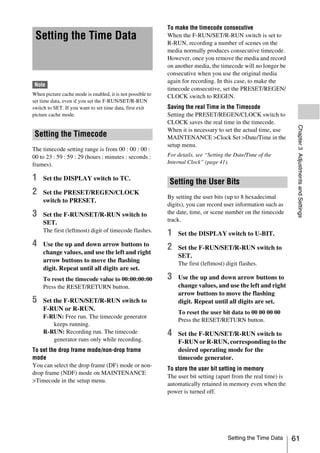
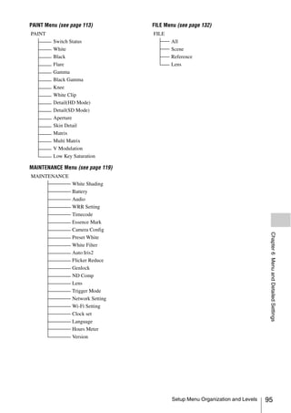
![Chapter 3 Adjustments and Settings
For menu operations, see “Basic Setup Menu Operations” (page 96).
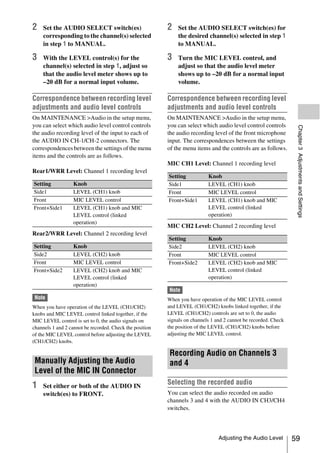
Setting the Video Format
Chapter 3 Adjustments and Settings
The following recording formats can be selected for different combinations of video resolution and system
frequency.
OPERATION >Format menu settings Video format (recording Frame size
HD/SD HD System Line Rec Format System Frequency a) format/system frequency)
HD 1080 HQ 1920 59.94i HQ 1920/59.94i 1920×1080
50i HQ 1920/50i
29.97P HQ 1920/29.97P
25P HQ 1920/25P
23.98P HQ 1920/23.98P
HQ 1440 59.94i HQ 1440/59.94i 1440×1080
50i HQ 1440/50i
29.97P HQ 1440/29.97P
25P HQ 1440/25P
23.98P HQ 1440/23.98P
SP 1440 59.94i SP 1440/59.94i
50i SP 1440/50i
23.98P b) SP 1440/23.98P
720 HQ 1280 59.94P HQ 1280/59.94P 720×1280
50P HQ 1280/50P
29.97P HQ 1280/29.97P
25P HQ 1280/25P
23.98P HQ 1280/23.98P
SD — DVCAM 59.94i DVCAM/59.94i 720×480
50i DVCAM/50i 720×576
29.97P c) DVCAM/29.97P 720×480
25P c) DVCAM/25P 720×576
a) 59.94i/29.97P/59.94P/23.98P: When OPERATION >Format >Country in the setup menu is set to [NTSC Area] or
[NTSC(J) Area]
50i/25P/50P: When OPERATION >Format >Country in the setup menu is set to [PAL Area]
b) 59.94i after 2-3 pulldown is recorded
c) Converted to PsF and recorded
Setting the Video Format 49](https://image.slidesharecdn.com/pmw-320lenk-120216080013-phpapp02/85/Sony-PMW-320K-Operation-Manual-49-320.jpg)
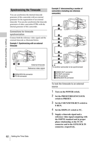
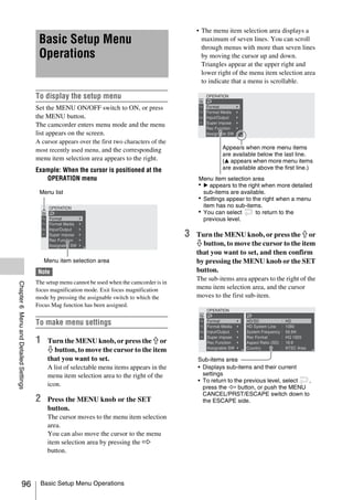
![Changing the Video Format
Adjusting the Black
Refer to the above table and change the settings of
the relevant items.
Balance and the White
Balance
1 Select OPERATION >Format in the
setup menu (see page 98).
To ensure excellent image quality when using this
camcorder, conditions may require that both the
black balance and the white balance be adjusted.
Black balance and white balance adjustment
values that are automatically set by the camcorder
and the various settings are stored in the
Chapter 3 Adjustments and Settings
camcorder memory and retained even when the
power is turned off.
2 Turn the MENU knob to select the item Black balance adjustment
to change, and press the knob. The black balance will require adjustment in the
following cases.
3 Turn the MENU knob to change the • When the camcorder is used for the first time
setting, and press the knob. • When the camcorder has not been used for a
A confirmation message appears. long time
• When the camcorder is used under conditions in
4 Select [Execute] to execute, or select which the surrounding temperature has changed
[Cancel] to cancel, and then press the greatly
MENU knob. • When the GAIN selector (L/M/H/Turbo) values
have been changed by using OPERATION
5 When the setting of HD/SD or Country >Gain Switch in the setup menu.
was changed, power the camcorder off It is not usually necessary to adjust the black
and on again. balance when using the camcorder after it has
been off.
White balance adjustment
Always readjust the white balance when the
lighting conditions change.
Adjusting the Black Balance
In automatic black balance mode, adjustments are
performed in the following order: black set and
black balance. Manual black balance adjustment
can be selected from the setup menu.
Note
Automatic black balance adjustment is disabled in the
following case.
• During recording
• In a special recording modes (Picture Cache Rec,
Interval Rec, Frame Rec, Slow & Quick)
• When the shutter mode is SLS
50 Adjusting the Black Balance and the White Balance](https://image.slidesharecdn.com/pmw-320lenk-120216080013-phpapp02/85/Sony-PMW-320K-Operation-Manual-50-320.jpg)
![1 Set the OUTPUT/DCC switch to CAM.
Adjusting the White Balance
2 Push the AUTO W/B BAL switch to
BLACK and release the switch. 1 Set the switches and selectors as shown
The message “Executing...” appears during below.
execution, and changes to “Done” when the • GAIN switch: L (set to a gain value that is
adjustment finishes. Adjustment values are as small as possible)
saved to memory automatically. • OUTPUT/DCC switch: CAM
• WHITE BAL switch: A or B 1)
Notes 1) Adjustment values are saved to memory B only
• During the black balance adjustment, the iris is when OPERATION >White Setting >White
automatically closed. Switch<B> in the setup menu, is set to
• During the black balance adjustment, the gain [Memory].
selection circuit is automatically activated so you may
2
Chapter 3 Adjustments and Settings
see flickering on the viewfinder screen, but this is not Set the FILTER selector to suit the
a fault. lighting conditions as follows.
• Output from the i.LINK connector stops temporarily if
you execute black balance adjustment during i.LINK 3 Place a white test card under the same
output. Output from the connector resumes when black lighting conditions as for the subject to
balance adjustment finishes. be shot and zoom up to it.
Alternatively, any white object such as a
If automatic black balance adjustment cloth or a wall can be used.
cannot be made The absolute minimum white area is as
If the black balance adjustment cannot be follows.
completed normally, an error message will appear Rectangle centered on the screen. The
for about three seconds on the viewfinder screen. lengths of the sides are 70% of the length
and width of the screen.
Possible messages are listed below.
Error message Meaning
NG: Iris Not The lens iris did not close;
Closed adjustment was impossible.
NG: Timeout Adjustment could not be
completed within the standard
number of attempts.
NG: Out of The difference between the
Range reference value and the current Note
value is so great that it exceeds Make sure there are not bright spots in the
the range. Adjustment was rectangle.
impossible.
If any of the above error messages is displayed,
4 Adjust the lens iris.
Manually adjusted lens: set the iris to an
retry the black balance adjustment.
appropriate setting.
If the error message occurs again, an internal
Lens with automatic iris: set the automatic/
check is necessary.
manual switch on the lens to automatic.
For information about this internal check, refer to
the Maintenance Manual. 5 Push the AUTO W/B BAL switch to
Note WHITE and then release the switch.
The message “Executing...” appears during
If the lens cable is not firmly connected to the LENS
execution, and changes to “OK: (color
connector, it may not be possible to adjust the lens iris. If
this happens, the black balance will be incorrect.
temperature of subject)” when the
adjustment finishes.
Adjusting the Black Balance and the White Balance 51](https://image.slidesharecdn.com/pmw-320lenk-120216080013-phpapp02/85/Sony-PMW-320K-Operation-Manual-51-320.jpg)
![The adjustment values are saved
automatically in the memory selected in
To change the color temperature when
step 1 (A or B). the ND filter is switched
You can assign electrical CC (color correction)
Note
filters to ND filters (see page 16). This allows you
If the camcorder has a zoom lens with an automatic
to change the color temperature automatically
iris, the iris may hunt 1) during the adjustment. To
when the ND filter is switched.
prevent this, adjust the iris gain knob (indicated as
IG, IS, or S) on the lens.
1 Set MAINTENANCE >White Filter
For details, refer to the lens operation manual. >ND Filter C.Temp in the setup menu
(see page 127) to On.
1) Hunting: Repeated brightening and darkening of
the image, resulting from repeated response to
automatic iris control.
2 To assign an electrical CC filter to
FILTER selector position number 1,
Chapter 3 Adjustments and Settings
If the automatic white balance adjustment select [ND FLT C.Temp<1>]. To assign
cannot be made it to positions 2 to 4, select [ND FLT
If the white balance adjustment cannot be
C.Temp<2-4>].
completed normally, an error message will appear
for about three seconds on the viewfinder screen. 3 Turn the MENU knob to select the
Possible messages are listed below. desired color temperature.
Error message Meaning As you turn the MENU knob, the color
NG: Low Light The white video level is too low.
temperature changes as follows: 3200K y
Either open the lens iris or 4300K y 5600K y 6300K.
increase the gain.
NG: Timeout Adjustment could not be
4 Repeat steps 2 and 3 as required.
completed within the standard
number of attempts. To switch between electrical CC filters
NG: High Light The white video level is too with an assignable switch
high. Either stop down the lens You can assign the function that switches
iris or change the ND filter. between electrical CC filters to an assignable
If any of the above error messages is displayed, switch. This allows you to switch between color
retry the white balance adjustment. If the error temperatures (3200K/4300K/5600K/6300K) that
message occurs again, an internal check is have been assigned to up to four positions (A to
necessary. D) with each press of the assignable switch.
Regardless of assignments to assignable
For information about this internal check, refer to
the Maintenance Manual. switches, you can also switch between the color
temperatures assigned to each position from a
RM-B150/B750 Remote Control Unit.
If you have no time to adjust the white
balance 1 Select MAINTENANCE >White Filter
Set the WHITE BAL switch to PRST. in the setup menu (see page 127).
This makes it possible to automatically set the
white balance to 5600K (factory default value) by 2 Select the position to which to assign a
pressing the COLOR TEMP. button. CC filter by selecting one of [Electrical
The color temperature to which the white balance CC<A>] to [Electrical CC <D>], and
is set when the COLOR TEMP. button is pressed then turn the MENU knob to select the
can be selected from among 3200K, 4300K, desired color temperature.
5600K, and 6300K on OPERATION As you turn the MENU knob, the color
>Assignable SW in the setup menu. You can also temperature changes as follows: 3200K y
assign color temperatures to the ASSIGN. 1/3 4300K y 5600K y 6300K.
switches or ASSIGNABLE 4/5 switches.
52 Adjusting the Black Balance and the White Balance](https://image.slidesharecdn.com/pmw-320lenk-120216080013-phpapp02/85/Sony-PMW-320K-Operation-Manual-52-320.jpg)
![To set no color temperature
Select “-----” with Electrical CC<C> or <D>
selected.
Setting the Electronic
When the assignable switch is pressed, the Shutter
setting for that position is not displayed. For
example, if “-----” is set for one position, then
switching between the remaining three
positions is carried out.
Shutter Modes
3 Repeat step 2 as required.
The shutter modes that can be used with the
4 Assign the electrical CC filter switching electronic shutter and the shutter speeds that can
function (ELECTRICAL CC) to an be selected are listed below.
assignable switch (see page 139).
Chapter 3 Adjustments and Settings
Standard mode
White balance memory Select this mode for shooting fast-moving
Values stored in memory are held until the white subjects with little blurring.
balance is next adjusted even when the camcorder You can set the shutter speed in one of two shutter
power is turned off. modes: Speed mode, in which the speed is set in
The camcorder has two white balance memories, seconds, and Angle mode, in which the speed is
A and B. You can automatically save adjustment set in degrees.
values for each ND filter in the memory that
Speed mode
corresponds to the WHITE BAL switch setting
(A or B). The camcorder has four built-in ND System Shutter speed (unit: seconds)
filters, allowing you to save a total of eight frequency
adjustment values (4 × 2). However, the contents 59.94i 1/ 1/ 1 1 1 1
60, 100, /120, /125, /250, /500,
of the memories are not linked to ND filter 59.94P 1/ 1/
50i 1000, 2000
settings in the following cases.
• When the number of memories allocated to 50P
29.97P 1/ a), 1/ a) 1/ , 1/ 1 1
each of A and B is limited to one by setting 40 50 , 60 100, /120, /125,
OPERATION >White Setting >Filter White 1/ , 1/ 1/ 1/
250 500, 1000, 2000
Memory in the setup menu to Off.
25P 1/ a), 1/ a), 1/ 1/ , 1/ 1
• When the electrical CC filter switching function 33 50 60, 100 120, /125,
1/ , 1/ 1 1
has been assigned to an assignable switch, or 250 500, /1000, /2000
when a remote control unit has been connected. 23.98P 1/ a), 1/ a), 1/ a), 1/ , 1/ , 1/ ,
32 48 50 60 96 100
(In these cases, the contents of white balance 1/ 1 1 1 1 1
memory are linked to electrical CC filter 120, /125, /250, /500, /1000, /2000
positions (A to D).) a) This speed cannot be selected when the camcorder is
in Slow & Quick Motion mode and OPERATION
Also, when OPERATION >White Setting >Rec Function >Frame Rate in the setup menu is set
>White Switch<B> in the setup menu is set to to a value that is greater than the system frequency.
[ATW (Auto Tracing White Balance)], and the Angle mode
WHITE BAL switch is set to B, the ATW 180°, 90°, 45°, 22.5°, and 11.25°
function is activated to automatically adjust the
white balance of the picture being shot for ECS (Extended Clear Scan) mode
varying lighting conditions.
Select this mode for obtaining images with no
horizontal bands of noise when shooting subjects
such as monitor screens.
Setting the Electronic Shutter 53](https://image.slidesharecdn.com/pmw-320lenk-120216080013-phpapp02/85/Sony-PMW-320K-Operation-Manual-53-320.jpg)

![CH3 switch Channel 3 recording target Setting Knob
FRONT Front microphone audio Side4 LEVEL (CH4) knob
REAR Audio signal input to AUDIO IN Front MIC LEVEL control
CH-1 connector Front+Side4 LEVEL (CH4) knob and
WIRELESS Wireless microphone audio MIC LEVEL control (linked
operation)
CH4 switch Channel 4 recording target You can now adjust the levels of audio
FRONT Front microphone audio channels 3 and 4 with the knobs selected
REAR Audio signal input to AUDIO IN here.
CH-2 connector
WIRELESS Wireless microphone audio
You can have the selection made automatically,
Chapter 3 Adjustments and Settings
as follows.
To automatically select the same audio as on
channels 1 and 2
Set MAINTENANCE >Audio >Audio CH3/4
Mode of the setup menu to [Ch 1/2].
Adjusting the audio recording levels
To adjust automatically
Set the AUDIO SELECT CH 3-4 switch to
AUTO.
To adjust manually
1 Set the AUDIO SELECT CH 3-4 switch
to MANUAL.
2 Select the knobs that adjust the audio
levels with the Audio CH3 Level and
Audio CH4 Level items under
MAINTENANCE >Audio in the setup
menu.
Audio CH3 Level: Channel 3 recording
level
Setting Knob
Side3 LEVEL (CH3) knob
Front MIC LEVEL control
Front+Side3 LEVEL (CH3) knob and
MIC LEVEL control (linked
operation)
Audio CH4 Level: Channel 4 recording
level
60 Adjusting the Audio Level](https://image.slidesharecdn.com/pmw-320lenk-120216080013-phpapp02/85/Sony-PMW-320K-Operation-Manual-60-320.jpg)
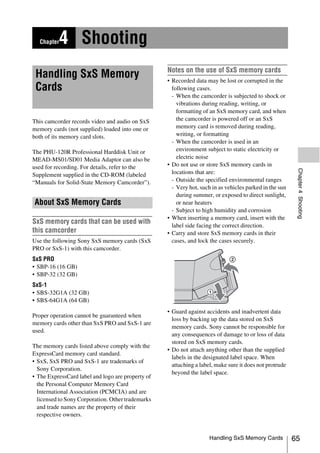
![The camcorder switches automatically to the
To eject SxS memory cards other card if the selected card becomes full during
recording.
1 Open the cover, and then press the
EJECT button to release the lock and Note
pull the button out. The SLOT SELECT button is disabled during playback.
Even when pressed, it does not change the selected slot.
Button operations are enabled when a thumbnail screen
(see page 82) is displayed.
Formatting (Initializing) SxS
Memory Cards
When you load an unformatted SxS memory card,
or load an SxS memory card that has been
formatted to other specifications, a message
“Cannot Use Media(A)/Unsupported File
System” appears in the viewfinder. In this case,
Press the button once format the memory card in the following way.
Chapter 4 Shooting
to release the lock.
Note
2 Press the EJECT button again to eject SxS memory cards must be formatted on an XDCAM
EX device. Cards in other formats cannot be used.
the card.
To format (initialize) a memory card
1 Select OPERATION >Format Media in
the setup menu (see page 99).
2 Select [Media(A)] (slot A) or [Media(B)]
(slot B).
3 Turn the MENU knob to select
[Execute], and then press the knob.
The confirmation message for formatting is
displayed on the viewfinder screen.
Note 4 Turn the MENU knob to select
Data integrity cannot be guaranteed if you power the “Execute”, and press the knob.
camcorder off or remove a memory card while the card Execution of the format starts.
is being accessed. Doing so may corrupt all data recorded
During execution of the format, a progress
on the card. Always make sure that the ACCESS lamp is
lit green or not lit before you power the camcorder off or
indication appears (%), and the ACCESS lamp
remove a memory card. lights in orange.
Recording and playback during format execution
Even during execution of a format, recording and
Selecting the SxS Memory Card to playback are possible using an SxS memory card
Use loaded into the other card slot.
When SxS memory cards are loaded in both slot If the format operation fails
A and slot B, you can press the SLOT SELECT A format operation may fail because the SxS
button to select the SxS memory card to use. memory card is write protected, or because it is
not the type of card specified for use with this
camcorder.
Handling SxS Memory Cards 67](https://image.slidesharecdn.com/pmw-320lenk-120216080013-phpapp02/85/Sony-PMW-320K-Operation-Manual-67-320.jpg)
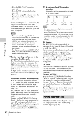
![1 Insert the SxS memory card to play (see 2 Turn the MENU knob to select
page 66). [Execute], and then press the knob.
2 Press the PREV button (see page 20) or
the F REV button (see page 20) to cue
up the clip to play.
3 Press the PLAY/PAUSE button.
The PLAY/PAUSE indicator lights, and the
playback picture appears in the viewfinder.
To pause the playback
Press the PLAY/PAUSE button.
The PLAY/PAUSE indicator flashes during
pause.
Press the button again to return to playback mode.
To play at high speed
Press the F FWD button (see page 20) or the
F REV button (see page 20).
To return to normal playback, press the PLAY/
Chapter 4 Shooting
PAUSE button.
To switch between memory cards
When two memory cards are loaded, press the
SLOT SELECT button (see page 23) to select the
active slot.
It is not possible to switch between memory cards
during playback.
To end playback
Press the STOP button: Playback stops, and the
camcorder enters E-E mode.
Press the THUMBNAIL button: Playback
stops, and a thumbnail screen (see page 82)
appears in the viewfinder.
Playback also stops and the timecode screen
appears in the viewfinder when you start
recording during playback, and when you eject an
SxS memory card.
Deleting Recorded Clips
You can use the assignable switches to delete the
last recorded clips (Last Clip DEL function).
You can also use the THUMBNAIL menu to delete all
recorded clips (All Clips DEL function) or to delete
selected clips. For details, see “Deleting Clips”
(page 90).
1 Turn on the assignable switch to which
the Last Clip DEL function has been
assigned (see page 137).
A confirmation message appears.
Basic Operations 71](https://image.slidesharecdn.com/pmw-320lenk-120216080013-phpapp02/85/Sony-PMW-320K-Operation-Manual-71-320.jpg)
![automatically whenever you select Frame Rec, • In picture cache mode, you cannot set time data
Interval Rec, or Slow & Quick Motion mode. by setting the F-RUN/SET/R-RUN switch to
• The data stored in picture cache memory is cleared SET.
when you change the system settings, for example by To set time data, exit picture cache mode.
selecting a different video format. Picture data from
• If the remaining free capacity of the media in
before the change is not recorded even if you start
recording immediately after the change. The
the currently selected slot is less than the picture
camcorder exits picture cache mode automatically. cache time, and the media in the other slot has
• It is not possible to set the picture cache time during enough remaining capacity, then data is
recording. recorded to the media in the other slot.
However, no data is recorded when there is no
1 In the setup menu, select OPERATION media in the other slot, and when the media in
>Rec Function >Picture Cache Rec. the other slot does not have enough remaining
For menu operations, see “Basic Setup Menu capacity. (A message appears in the viewfinder
Operations” (page 96). to inform you that there is not enough remaining
capacity.)
2 Turn the MENU knob to select [On], • Shot marks are not recorded if they are set
and then press the knob. before the recording start operation.
• When you select a video format that supports
3 Select [P. Cache Rec Time], turn the i.LINK HDV output and play a clip that was
Chapter 4 Shooting
MENU knob to select the desired recorded in picture cache mode, two or more
picture cache time, and then press the frames with the same picture and timecode may
knob. follow on each other.
You can select from 0-2sec, 2-4sec, 4-6sec, • i.LINK output is possible during picture cache
6-8sec, 8-10sec, 10-12sec, 12-14sec, and recording. However, the picture cache time is
13-15sec. limited.
If power is lost during recording
Once made, picture cache mode settings remain • If you set the camcorder’s POWER switch to
in effect until changed. OFF, the camcorder is powered off
Instead of carrying out steps 1 and 2, you can also automatically after a few seconds, during which
select picture cache mode by using an assignable the media is accessed to record the video and
switch to which the Picture Cache function has audio data stored in the camcorder’s memory up
been assigned (see page 136). to that point.
Camcorder data handling while recording in • If power is lost because the battery was
picture cache mode removed, the DC cable was disconnected, or the
Recording procedures in picture cache mode are power was turned off on the AC adaptor side,
basically the same as normal recording then the video and audio data stored in memory
procedures. However, note the following is lost. The data stored in memory is not
differences with respect to how the camcorder recorded. Be careful to avoid this when
handles video, time, and output data. exchanging the battery.
• If you start recording while the media is being
accessed, the start point of the video that is
actually recorded may be later than the
Recording Time-lapse Video
currently specified picture cache time. Because (Interval Rec Function)
the delay increases as the number of recorded
clips increases, you should avoid rapid start- The camcorder’s Interval Rec function allows
and-stop recording operations in picture cache you to capture time-lapse video to the
mode. camcorder’s internal memory. This function is an
• Regardless of the setting of the F-RUN/SET/ effective way to shoot slow-moving subjects.
R-RUN switch, the advance mode of the When you start recording, the camcorder
internal timecode generator is always F-RUN. automatically records a specified number of
frames at a specified interval time.
Advanced Operations 73](https://image.slidesharecdn.com/pmw-320lenk-120216080013-phpapp02/85/Sony-PMW-320K-Operation-Manual-73-320.jpg)
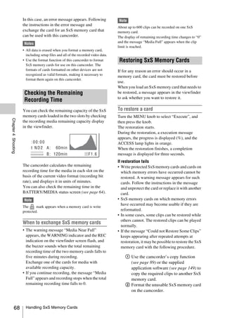
![Interval time 2 Turn the MENU knob to select [On],
and then press the knob.
The camcorder enters Interval Rec mode, the
“Interval” indication on the viewfinder
screen flashes.
3 Select [Number of Frames], turn the
MENU knob to select the number of
frames to record in one take, and then
press the knob.
You can select from 1, 3, 6, 9 (or from 2, 6,
12 when the video format setting is 720/
59.94P or 720/50P).
Number of frames in one take
A pre-lighting function is available when Interval 4 Select [Interval Time], turn the MENU
Rec is enabled. This function automatically turns knob to select the desired interval, and
on a video light before recording starts, which then press the knob.
allows you to record pictures under stable light You can select 1 to 10/15/20/30/40/50 sec,
and color temperature conditions. 1 to 10/15/20/30/40/50 min, 1 to 4/6/12/24
Chapter 4 Shooting
hour.
Interval Rec settings and shooting 5 As required, select [Pre-Lighting], turn
Notes the MENU knob to select the length of
lighting time before recording starts,
• The Interval Rec function cannot be used at the same
time as the picture cache, Frame Rec, or Slow & Quick
and then press the knob.
Motion function. When you select Interval Rec mode, You can select 1 to 10/15/20/30/40/50 sec,
the picture cache, Frame Rec, and Slow & Quick 1 to 10/15/20/30/40/50 min, 1 to 4/6/12/24
Motion functions are disabled. When you select hour.
picture cache, Frame Rec, or Slow & Quick Motion
mode, the Interval Rec function is disabled. Notes
• The data stored in picture cache memory is cleared • If you want to turn the video light on before the start of
when you change the system settings, for example by recording, set the camcorder’s LIGHT switch to
selecting a different video format. Picture data from [AUTO]. The video light’s switch must also be turned
before the change is not recorded even if you start on. When this is done, the video light turns on and off
recording immediately after the change. The automatically. However, the video light remains lit
camcorder exits picture cache mode automatically. when the time that it is off is five seconds or less.
• Interval Rec settings cannot be changed during • If you set the LIGHT switch to [MANUAL] and turn
recording. the video light’s switch on, the video light is always lit.
• Interval Rec is disabled when the following formats (It does not go on and off automatically.)
are selected.
- SP 1440/59.94i or SP 1440/50i, when the output The camcorder exits Interval Rec mode when it is
setting is HD and OPERATION >Input/Output powered off, but the number of frames, interval
>i.LINK I/O in the setup menu is set to [Enable] time, and pre-lighting settings are maintained.
- SP 1440/23.98P (pull-down recording) You do not need to set them again the next time
- Other than HQ 1920/23.98P or HQ 1280/23.98P, you shoot in Interval Rec mode.
when the output setting is SD and OPERATION
>Input/Output >i.LINK I/O in the setup menu is set To shoot in Interval Rec mode
to [Enable] Make the settings and preparations described in
To make Interval Rec settings “Basic Operations” (page 69), secure the
camcorder so that it does not move, and begin
1 Select OPERATION >Rec Function shooting.
>Interval Rec in the setup menu.
When recording starts, the “Interval” indication
For menu operations, see “Basic Setup Menu
in the viewfinder changes from flashing to lit, and
Operations” (page 96).
74 Advanced Operations](https://image.slidesharecdn.com/pmw-320lenk-120216080013-phpapp02/85/Sony-PMW-320K-Operation-Manual-74-320.jpg)
![“INT REC” and “INT STBY” appear
alternatively at the position of the REC Shooting Stop Motion Animations
indication. The TALLY indicators and the tally (Frame Rec Function)
indicator on the front panel of the viewfinder light
as they do during normal recording. The Frame Rec function is useful for shooting
If you are using the pre-lighting function, the stop motion animations, such as animations with
video light comes on before recording starts. puppets or clay figures.
Each time that you press the recording start
To stop shooting
button, the camcorder shoots a specified number
Stop the recording.
of frames and then stops.
When shooting ends, the video data stored in
memory up to that point is written to the media. Frame Rec settings and shooting
To exit Interval Rec mode Notes
Do one of the following. • The Frame Rec function cannot be used at the same
• Set the POWER switch to OFF. time as the picture cache, Interval Rec, or Slow &
• With the camcorder in recording standby mode, Quick Motion function. When you select Frame Rec
set OPERATION >Rec Function >Interval Rec mode, the picture cache, Interval Rec, and Slow &
in the setup menu to “Off”. Quick Motion functions are disabled. When you select
picture cache, Interval Rec, or Slow & Quick Motion
Chapter 4 Shooting
Limitations during recording mode, the Frame Rec function is disabled.
• The i.LINK (HDV/DV) connector cannot be • The data stored in memory is cleared when you change
used. the system settings, for example by selecting a
• Regardless of the setting of the F-RUN/SET/ different video format. Picture data from before the
R-RUN switch, the advance mode of the change is not recorded even if you start recording
internal timecode generator is always F-RUN. immediately after the change. The camcorder exits
• Audio cannot be recorded. Frame Rec mode automatically.
• Recording review is not possible. • Frame Rec settings cannot be changed during
recording.
• If you press the SLOT SELECT button, the
• Frame Rec is disabled when the following formats are
camcorder completes recording of the specified
selected.
number of frames, creates a clip, and switches
- SP 1440/59.94i or SP 1440/50i, when the output
to the other media. setting is HD and OPERATION >Input/Output
• Genlock is not possible. >i.LINK I/O in the setup menu is set to Enable
If power is lost during recording - SP 1440/23.98P (pull-down recording)
• If you set the camcorder’s POWER switch to - Other than HQ 1920/23.98P or HQ 1280/23.98P,
when the output setting is SD and OPERATION
OFF, the camcorder is powered off
>Input/Output >i.LINK I/O in the setup menu is set
automatically after a few seconds, during which
to Enable
the media is accessed to record the video and
audio data stored in the camcorder’s memory up To make Frame Rec settings
to that point.
• If power is lost because the battery was 1 Select OPERATION >Rec Function
removed, the DC cable was disconnected, or the >Frame Rec in the setup menu.
power was turned off on the AC adaptor side, For menu operations, see “Basic Setup Menu
then the video and audio data shot up to that Operations” (page 96).
point may be lost (maximum 10 seconds). Be
careful to avoid this when exchanging the 2 Turn the MENU knob to select [On],
battery. and then press the knob.
The camcorder enters Frame Rec mode, the
“Frame Rec” indication on the viewfinder
screen flashes.
3 Select [Number of Frames], turn the
MENU knob to select the number of
Advanced Operations 75](https://image.slidesharecdn.com/pmw-320lenk-120216080013-phpapp02/85/Sony-PMW-320K-Operation-Manual-75-320.jpg)
![frames to record in one take, and then If power is lost during recording
press the knob. • If you set the camcorder’s POWER switch to
You can select from 1, 3, 6, 9 (or from 2, 6, OFF, the camcorder is powered off
12 when the video format setting is 720/ automatically after a few seconds, during which
59.94P or 720/50P). the media is accessed to record the video and
audio data stored in the camcorder’s memory up
The camcorder exits Frame Rec mode when it is to that point.
powered off, but the setting for the number of • If power is lost because the battery was
frames setting is maintained. You do not need to removed, the DC cable was disconnected, or the
set it again the next time you shoot in Frame Rec power was turned off on the AC adaptor side,
mode. then the video and audio data shot up to that
point may be lost (maximum 10 seconds). Be
To shoot in Frame Rec mode
careful to avoid this when exchanging the
Make the settings and preparations described in
battery.
“Basic Operations” (page 69), secure the
camcorder so that it does not move, and begin
shooting. Shooting with Slow & Quick
When recording starts, the “Frame Rec”
Motion
indication in the viewfinder changes from
Chapter 4 Shooting
When the camcorder is in HD mode and the video
flashing to lit, and “FRM REC” and “FRM
format (see page 49) is set to one of the formats
STBY” appear alternatively at the position of the
listed below, you can specify a recording frame
REC indication. The TALLY indicators and the
rate that is different from the playback frame rate.
tally indicator on the front panel of the viewfinder
When the Country setting is [NTSC Area]/
light as they do during normal recording.
[NTSC Area(J)]: HQ 1920/29.97P, HQ
To stop shooting 1920/23.98P, HQ 1280/59.94P, HQ 1280/
Stop the recording. 29.97P, HQ 1280/23.98P
When the Country setting is [PAL Area]: HQ
When shooting ends, the video data stored in 1920/25P, HQ 1280/50P, HQ 1280/25P
memory up to that point is written to the media.
To exit Interval Rec mode By shooting with a frame rate that differs from the
Do one of the following. playback frame rate, you can obtain slow and
• Set the POWER switch to OFF quick motion effects that are smoother than low-
• With the camcorder in recording standby mode, speed or high-speed playback of content recorded
set OPERATION >Rec Function >Interval Rec at the normal frame rate.
in the setup menu to [Off]. Example
Limitations during recording When the video format is HQ 1280/23.98P, you
• The i.LINK (HDV/DV) connector cannot be can obtain quick-motion effects by setting the
used. frame rate to 1 to 23, and obtain slow-motion
• Regardless of the setting of the F-RUN/SET/ effects by setting the frame rate to 25 to 60.
R-RUN switch, the advance mode of the
internal timecode generator is always R-RUN. Slow & Quick Motion settings and
• Audio cannot be recorded. shooting
• Recording review is not possible.
• If you press the SLOT SELECT button, the Notes
camcorder completes recording of the specified • The Slow & Quick Motion function cannot be used at
number of frames, creates a clip, and switches the same time as the picture cache, Interval Rec, or
to the other media. Frame Rec function. When you select Slow & Quick
• Genlock is not possible. Motion mode, the picture cache, Interval Rec, and
Frame Rec functions are disabled. When you select
picture cache, Frame Rec, or Interval Rec mode, the
Slow & Quick Motion function is disabled.
76 Advanced Operations](https://image.slidesharecdn.com/pmw-320lenk-120216080013-phpapp02/85/Sony-PMW-320K-Operation-Manual-76-320.jpg)
![• Slow & Quick Motion is disabled when the slow Note
shutter function (viewfinder display “SLS”) function is
enabled. The slow shutter function is disabled when It takes longer than normal for recording to stop when
the Slow & Quick Motion function is enabled. Frame Rate is set to a low value (for a slow frame rate).
• Slow & Quick Motion is disabled when OPERATION To exit Slow & Quick Motion mode
>Input/Output >i.LINK I/O in the setup menu is set to With the camcorder in recording standby mode,
[Enable]. When Slow & Quick Motion is enabled, set OPERATION >Rec Function > Slow & Quick
i.LINK I/O is fixed as [Disable].
in the setup menu to “Off”.
• Slow & Quick Motion settings cannot be changed
during recording. Limitations during recording
• The i.LINK (HDV/DV) connector cannot be
To make Slow & Quick Motion settings
used.
1 Select OPERATION >Rec Function > • Regardless of the setting of the F-RUN/SET/
Slow & Quick in the setup menu. R-RUN switch, the advance mode of the
internal timecode generator is always R-RUN.
For menu operations, see “Basic Setup Menu
• Audio cannot be recorded when the recording
Operations” (page 96).
and playback frame rates differ.
2 Turn the MENU knob to select [On], • Recording review is not possible.
and then press the knob. • If you change the recording frame rate to a value
faster than the current shutter speed, the shutter
The camcorder enters Slow & Quick Motion
Chapter 4 Shooting
speed is changed to the slowest value for which
mode, and the “S&Q STBY” indication in
shooting is possible.
the viewfinder lights.
Example: If the frame rate is 32 and the shutter
3 Select [Frame Rate], turn the MENU speed is 1/40, and you change the frame rate to
knob to select the recording frame rate, 55, then the shutter speed is changed to 1/60.
and then press the knob. If is not possible to select a shutter speed that is
The setting range for the frame rate is as slower than the recording frame rate.
follows. • Genlock is not possible.
System lines Frame rate
1080 1 to 30
Framing Shots with the Freeze
720 1 to 60 Mix Function
When you finish making these settings, the The freeze mix function allows you to
system frequency and the frame rate appear at the temporarily overlap a still image (freeze picture)
top of the viewfinder screen. You can change the from a clip shot in HD mode onto the current
frame rate while viewing the display in the camera picture. This makes it easier to frame the
viewfinder by turning the MENU knob. shot.
The Slow & Quick Motion mode setting and the
frame rate are retained even after the camcorder is Note
powered off. The freeze mix function is not available in the following
cases.
To shoot in Slow & Quick Motion mode
• When the recording format is SP 1440/23.98P
Shoot as described in “Basic Operations”
• When the video formats of the recorded picture and the
(page 69). camera picture differ
• When you are shooting in Slow & Quick Motion mode
When recording starts, the “S&Q STBY” or slow shutter mode
indication in the viewfinder changes to the • When there is i.LINK input
“z S&Q REC” indication. The TALLY
indicators and the tally indicator on the front To display a freeze mix picture
panel of the viewfinder light as they do during
normal recording.
1 Play a clip or conduct a recording
To stop shooting review of a clip with the same format as
Stop the recording. the camera picture.
Advanced Operations 77](https://image.slidesharecdn.com/pmw-320lenk-120216080013-phpapp02/85/Sony-PMW-320K-Operation-Manual-77-320.jpg)
![information that it contains, such as file names,
Loading a Planning Metadata File date and time of creation, and titles.
into Camcorder’s Internal Memory
1 Under OPERATION >Plan.Metadata
To record planning metadata together with >Properties in the setup menu, select
recording clips, you need to load a planning [Execute].
metadata file into the camcorder’s memory before
starting to shoot. 2 Turn the MENU knob to select
There are two ways to load files. [Execute], and then press the knob.
• Load a file that has been written to the following The PLANNING METADATA
directories on an SxS memory card. PROPERTIES list appears.
The list contains the following information.
Media Directory to which files are
written Item Information
SxS memory BPAV/General/Sony/Planning File Name File name
card Assign ID Assign ID
SDHC PRIVATE/SONY/BPAV/General/ Created Date and time of creation
Sony/Planning Modified Date and time of most recent
• When a Wi-Fi connection is made between the modification
Chapter 4 Shooting
camcorder and a computer, operate the Web Modified by Name of person who
menu built in the camcorder from the computer modified the file
to transfer a file. Title Title1 specified in file (ASCII
format clip name)
For details on how to use the Web menu to load a
Title2 Title2 specified in file (UTF-8
planning metadata file, refer to the Supplement
format clip name)
supplied in the CD-ROM (labeled “Manuals for
Material Gp Number of clips in material
Solid-State Memory Camcorder”).
group a)
Shot Mark0 to Names defined in file for Shot
To load a planning metadata file by menu Shot Mark9 Mark 0 to Shot Mark 9
operation
a) Material group: A group of clips recorded with
Do the following procedures with OPERAION the same planning metadata.
>Planning Metadata in the setup menu.
You can turn the MENU knob to scroll the
1 Insert an SxS memory card into the list.
memory card slot A or B, and set Load/ After turning the MENU knob to select an
Slot(A) or Load/Slot(B) to [Execute]. item, you can press the SET button to display
A file list appears. the selected item only.
Note
The file list displays up to 64 files.
To clear the planning metadata loaded
Even if the total number of planning metadata files
is 64 or less, all of the planning metadata files may 1 Under OPERATION >Plan.Metadata
not appear if the directory where they are located on >Clear in the setup menu, select
the SxS memory card (General/Sony/Planning) [Execute].
contains 512 or more files.
2 Turn the MENU knob to select
2 Turn the MENU knob to select a file to [Execute], and then press the knob.
load and press the knob. Deletion of the file starts.
The message “Clear Planning Metadata File
To display detailed information in OK” appears when the deletion finishes.
planning metadata
After loading planning metadata into the
camcorder, you can check the detailed
Planning Metadata Operations 79](https://image.slidesharecdn.com/pmw-320lenk-120216080013-phpapp02/85/Sony-PMW-320K-Operation-Manual-79-320.jpg)
![</Properties>3
Defining Clip Names in Planning </PlanningMetadata>3
Metadata Notes
The following two types of clip name strings can • When you create a file, enter each statement as a single
be written in a planning metadata file. line with a CRLF only after the last character in the
statement line, and do not enter spaces except where
• The ASCII format name that appears in the
specified.
viewfinder
• Up to 44 bytes (or characters) string is available for the
• The UTF-8 format name that is actually clip name.
registered as the clip name If the UTF-8 format string exceeds 44 bytes, 44 bytes
string is used as the clip name.
You can select which type of clip name is If only ASCII format name is specified, 44 characters
displayed with OPERAION >Planning Metadata string is used as the clip name.
>Clip Name Disp in the setup menu. When neither an ASCII format name string nor UTF-8
When a clip name is set with planning metadata, format name string can be used, the standard format
the name is displayed under the depth of field clip name is used.
indication on the viewfinder screen. You can use the Sony Planning Metadata Add-in
application software supplied with the CBK-WA01
Note Wi-Fi Adapter to define clip names. For details, refer
When you define both of ASCII format name and UTF- to the Operating Instructions supplied with the CBK-
Chapter 4 Shooting
8 format name with planning metadata, the UTF-8 WA01.
format string is used as the clip name string. If you define
either of ASCII format name and UTF-8 format name
with planning metadata, the defined format name is
To set clip names
displayed though it is not selected by menu setting.
1 Load a planning metadata file that
Clip name string example contains clip names into this
camcorder.
Use a text editor to modify the two fields in the
<Title> tag that contain the clip name strings. 2 Set OPERATION >Clip >Auto Naming
The shaded fields in the example are clip name in the setup menu to [Plan].
strings. “Typhoon” is described in ASCII format Each time that you record a clip, the unit
(up to 44 characters). “Typhoon_Strikes_Tokyo” automatically generates a name consisting of
is described in UTF-8 format (up to 44 bytes). the clip name defined in the planning
“sp” indicates a space and 3 indicates a carriage metadata file, with the addition of an
return. underbar (_) and a five-digit serial number
(00001 to 99999).
<?xmlspversion="1.0"spencoding=" Examples:
UTF-8"?>3 Typhoon_Strikes_Tokyo_00001,
<PlanningMetadataspxmlns="http:// Typhoon_Strikes_Tokyo_00002, ...
xmlns.sony.net/pro/metadata/
planningmetadata"spassignId=" Note
P0001"spcreationDate=" When you load another planning metadata file, the serial
2011-08-20T17:00:00+09:00"sp number returns to 00001 with the next recording
lastUpdate=" operation.
2011-09-28T10:30:00+09:00"sp To select the clip name display format
version="1.00">3 When names are defined in both ASCII format
<PropertiessppropertyId=" and UTF-8 format, you can use OPERATION
assignment"spupdate=" >Clip >Clip Name Disp in the setup menu to
2011-09-20T10:30:00+09:00"sp select which of the names to display on the
modifiedBy="Chris">3 viewfinder screen.
<TitlespusAscii=" Typhoon "sp To display ASCII format names: Select
xml:lang="en"> Typhoon_Strikes_Tokyo Title1(ASCII).
</Title>3 The clip name becomes
80 Planning Metadata Operations](https://image.slidesharecdn.com/pmw-320lenk-120216080013-phpapp02/85/Sony-PMW-320K-Operation-Manual-80-320.jpg)
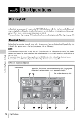
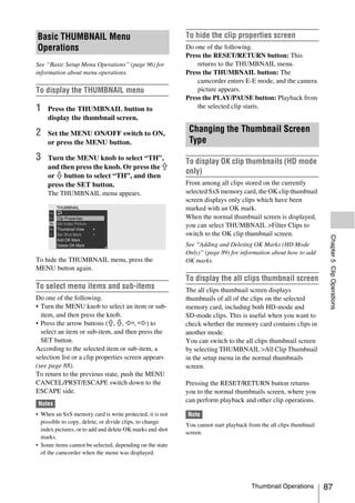
![a Index picture f Video format of recording
When a clip is recorded, its first frame is set
automatically as the index picture. You can g Special recording information
change to index picture to any frame (see This displays the mode of clips that have been
page 93). recorded in a special mode (Slow & Quick
Motion, Interval Rec, Frame Rec).
b Lock mark For Slow & Quick Motion clips, the frame rates
Indicates the selected clip is marked with an OK are displayed to the right as [Recording frame
mark and protected. rate/Playback frame rate] fps.
c Date and start time of recording h OK mark
An OK mark appears only when the clip has been
d Clip name marked with an OK mark (see page 89).
e Independent AV file icon i File format
This appears only when a clip is an independent Indicates the file format of the selected clip
AV file. SxS memory cards may contain (MP4).
independent files that have been added directly
from a computer. Because independent files lack j Clip duration
the associated management files, some operations
and information displays may not be available. k Timecode
This is the timecode of the index picture.
SD mode thumbnail screen
Chapter 5 Clip Operations
The icon of the currently selected SxS memory card is highlighted.
Cursor (yellow) (If the card is write protected, a lock appears on the left.)
Clip number/Number of components
a Take mark b Index picture
Indicates that the file size is larger than 2 GB, and When a clip is recorded, its first frame is set
that the clip has been split before being saved. automatically as the index picture.
You can check the segment files on the expand
thumbnail screen (see page 91).
Clip Playback 83](https://image.slidesharecdn.com/pmw-320lenk-120216080013-phpapp02/85/Sony-PMW-320K-Operation-Manual-83-320.jpg)
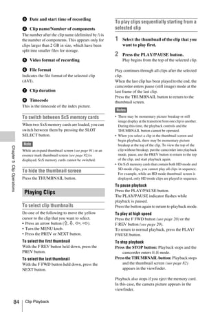
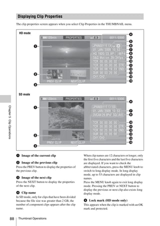
![f OK mark (HD mode only) An OK mark is added to the selected clip.
This appears only when an OK mark has been
added. To delete an OK mark
A Delete OK Mark item appears in the
g Date and start time of recording
THUMBNAIL menu when you have selected a
h File format clip that has an OK mark.
The file format of the clip (MP4 or AVI) appears. 1 In the thumbnail screen, select
i Special recording information (HD THUMBNAIL >Delete OK Mark.
The screen changes to the clip properties
mode only)
screen, and a confirmation message appears
This displays the mode of clips that have been
beneath the index picture.
recorded in a special mode (Slow & Quick
Motion, Interval Rec, Frame Rec). 2 Select [Execute], and press the MENU
For Slow & Quick Motion clips, the frame rates knob.
are displayed to the right as [Recording frame
rate/Playback frame rate]. The OK mark is deleted from the selected clip.
j Timecode of the displayed image
k Timecode of the recording start point
Copying Clips
You can copy clips to other SxS memory cards.
l Timecode of the recording end point
Clips are copied to destination SxS memory cards
m Duration using the same names as the original clips.
Chapter 5 Clip Operations
Notes
n Recorded audio channels
• If a clip with the same name already exists at the copy
destination SxS memory card, a one-digit number in
o Video format of recording
parentheses is added to the original name.
The number in parentheses is the smallest number that
does not exist at the copy destination.
Adding and Deleting OK Marks
Examples:
(HD Mode Only) ABCD0002tABCD0002(1)
ABCD0002(1)tABCD0002(2)
You can add OK marks to clips. This makes it
ABCD0005(3)tABCD0005(4)
possible to display thumbnails of only the clips • If the parenthetical numbers (1) to (9) already exist at
that you need by pressing the THUMBNAIL the copy destination, it is not possible to copy any more
button. clips under that name. (A tenth clip cannot be copied.)
Clips with OK marks cannot be deleted or • A message appears if there is not enough free capacity
divided. If you want to delete or divide such a at the copy destination SxS memory card. Exchange
clip, delete the OK mark first. the card for one with more free capacity.
• When multiple clips are recorded in a source SxS
memory card, it may not be possible to copy all clips
To add an OK mark
to the end. Depending on memory characteristics and
usage of the memory cards, this can occur even when
1 In the thumbnail screen, select the source and destination memory cards have the
THUMBNAIL >Add OK Mark. same capacity.
The screen changes to the clip properties
screen, and a confirmation message appears 1 In the thumbnail screen, select the
beneath the index picture. thumbnail of the clip to copy, and then
select THUMBNAIL >Copy Clip.
2 Select [Execute], and press the MENU The screen changes to the properties screen
knob. of that clip, and a confirmation message
appears beneath the index picture.
Thumbnail Operations 89](https://image.slidesharecdn.com/pmw-320lenk-120216080013-phpapp02/85/Sony-PMW-320K-Operation-Manual-89-320.jpg)
![2 Select [Execute], and press the MENU To copy all files together with all clips, select
knob. THUMBNAIL >Copy All >All Clips & General
The copy starts. Files in step 1.
During the copy, an execution message and
progress bar are displayed. Deleting Clips
When the copy finishes, the display returns to the
You can delete clips from SxS memory cards.
thumbnail screen.
To cancel a copy operation Note
Press the RESET/RETURN button. HD clips with OK marks cannot be deleted.
The copy is cancelled, and the display returns to If you want to delete such clips, first delete the OK marks
the thumbnail screen. (see page 89).
To batch copy groups of clips/files 1 In the thumbnail screen, select the
thumbnail of the clip to delete, and then
You can batch copy groups of clips from one SxS select THUMBNAIL >Delete Clip.
memory card to another SxS memory card. The screen changes to the properties screen
When both HD-mode and SD-mode clips exist on of that clip, and a confirmation message
the source SxS memory card, only clips in the appears beneath the index picture.
currently selected mode are copied. This is a
convenient way to extract clips in one of the 2 Select [Execute], and press the MENU
modes. knob.
You can also copy of the files in the General The clip is deleted.
directory, either together with or separately from
clips. In the thumbnail screen, the clips that followed
Chapter 5 Clip Operations
the deleted clip move up one position.
1 In the thumbnail screen, select the
thumbnails of the clips to copy and then
To batch delete groups of clips
select THUMBNAIL >Copy All >All
Clips. You can batch delete groups of clips from an SxS
The confirmation message “Copy All Clip?” memory card.
appears. Notes
2 Select [Execute], and press the MENU • When both HD-mode and SD-mode clips exist on the
SxS memory card, only clips in the currently selected
knob. mode are deleted.
The copy starts. • In HD mode, clips with OK marks are not deleted,
During the copy, the progress of the copy is even when a deletion is executed for a group of clips
displayed. that includes them.
If you executed the copy in HD mode, only
HD-mode clips are copied. 1 In the thumbnail screen, select the
If you executed the copy in SD mode, only thumbnails of the clips to delete and
SD-mode clips are copied. then select THUMBNAIL >Delete All
To cancel the copy operation Clips.
Press the RESET/RETURN button. The confirmation message “Delete All
Clips?” appears.
When the copy finishes
A completion message appears, and the 2 Select [Execute], and press the MENU
THUMBNAIL menu screen appears again. knob.
To copy all files in the General directory The deletion starts.
To copy all files only, without copying clips, During the deletion, the progress of the
select THUMBNAIL >Copy All >General Files deletion is displayed.
in step 1.
90 Thumbnail Operations](https://image.slidesharecdn.com/pmw-320lenk-120216080013-phpapp02/85/Sony-PMW-320K-Operation-Manual-90-320.jpg)
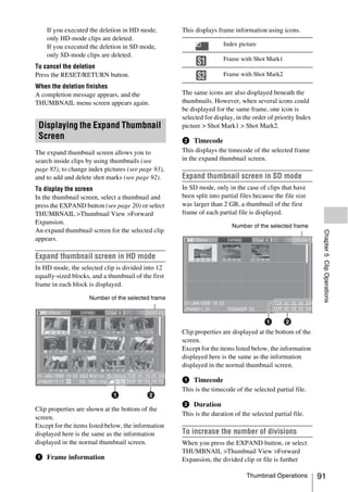
![divided into 12 equally-sized blocks (a clip or file
that has been divided into 12 is further divided
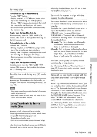
Example shot mark thumbnail screen
into 12, for 12 × 12 = 144 divisions). You can (with Shot Mark1 selected)
repeat the same operation to increase the number
of division.
To return to the previous division level
Press the EXPAND button with the SHIFT button S1 S2 S2 S1
held down, or select THUMBNAIL >Thumbnail
View >Back Expansion. The expand thumbnail S1 S1
screen returns to the previous division level.
Displaying the Shot Mark
Thumbnail Screen (HD Mode
Only)
The properties of the clip appear at the bottom of
In the shot mark thumbnail screen (shown only in the screen.
HD mode), you can search for shot marks in clips Except for the following item, the information
(see page 85), change index pictures (see displayed here is the same as the information
page 93), and add and delete shot marks (see displayed in the expand thumbnail screen.
page 92).
a Timecode
1 In the thumbnail screen, select the This is the timecode of the selected frame in the
thumbnail of a clip, and press the shot mark thumbnail screen.
Chapter 5 Clip Operations
ESSENCE MARK button (see page 22)
or select THUMBNAIL >Thumbnail
View >Essence Mark Thumbnail. Adding and Deleting Shot Marks
The shot mark thumbnail screen appears, and (HD Mode Only)
a selection list is displayed.
In the shot mark thumbnail screen (see page 92)
2 Select the type of the essence mark or the expand thumbnail screen (see page 91),
thumbnail screen. you can add thumbnails to any frame of clips
All: Thumbnail display of all frames marked recorded in HD mode, and delete recorded shot
with essence marks. marks.
Shot Mark1: Display only frames marked
with Shot Mark1 marks. To add shot marks
Shot Mark2: Display only frames marked
with Shot Mark2 marks. 1 Select the frame where you want to add
You can also select Shot Mark 0 and Shot
a shot mark, and then select
Mark 3 to Shot Mark 9.
THUMBNAIL > Set Shot Mark > Add
If you have recorded clips by using planning
Shot Mark1 (or Add Shot Mark2).
metadata that defined names for Shot Mark 0
The properties screen of the selected frame
to Shot Mark 9, the defined names are
appears, and a confirmation message appears
displayed instead of the above item names in
below the image.
the list.
2 Select [Execute], and press the MENU
knob.
92 Thumbnail Operations](https://image.slidesharecdn.com/pmw-320lenk-120216080013-phpapp02/85/Sony-PMW-320K-Operation-Manual-92-320.jpg)
![The properties screen of the selected frame
To delete shot marks appears, and a confirmation message appears
below the image.
1 Select the frame where you want to
delete a shot mark, and then select 2 Select [Execute], and press the MENU
THUMBNAIL > Set Shot Mark > knob.
Delete Shot Mark1 (or Delete Shot The clip is divided at the selected frame, and
Mark2). two clips with different names are created.
The properties screen of the selected frame
appears, and a confirmation message appears The first four characters of the clip name are
below the image. taken from the name of the original clips, and the
last four characters are new serial numbers.
2 Select [Execute], and press the MENU
Example: When the name of a newly recorded
knob.
clip would be EFGH0100, and a clip named
ABCD0002 is divided, the names of the two
Changing Clip Index Pictures newly created clips are ABCD0100 and
ABCD0101.
(HD Mode Only)
Note
In the shot mark thumbnail screen (see page 92) When there is not enough remaining capacity on the SxS
or the expand thumbnail screen (see page 91), memory cards to store the divided clips, a message
you can set the selected frame as the clip index appears to inform you that there is not enough capacity.
picture in HD mode.
1 Select the thumbnail of the frame that
Chapter 5 Clip Operations
you want to use as the index picture,
and then select THUMBNAIL >Set
Index Picture.
The properties screen of the selected frame
appears, and a confirmation message appears
below the image.
2 Select [Execute], and press the MENU
knob.
Note
Even if you set the index picture to a frame that is not the
first frame of a clip, playback of that clip from a
thumbnail screen always begins at the first frame.
Dividing Clips (HD Mode Only)
In the expand thumbnail screen (see page 91) and
the shot mark thumbnail screen (see page 92) ,
HD-mode clips can be divided into two clips at
the selected frame.
1 Select the thumbnail of the frame where
you want to divide the clip, and then
select THUMBNAIL >Divide Clip.
Thumbnail Operations 93](https://image.slidesharecdn.com/pmw-320lenk-120216080013-phpapp02/85/Sony-PMW-320K-Operation-Manual-93-320.jpg)
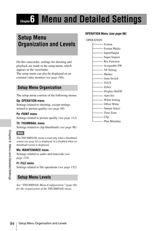
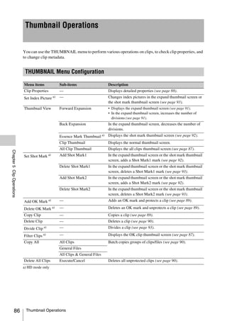
![4 Turn the MENU knob, or press the J or 1 Turn the MENU knob, or press the J or
j button, to move the cursor to the sub- j button, to select a character, and then
item that you want to set, and then confirm by pressing the MENU knob or
confirm the selection by pressing the the SET button.
MENU knob or the SET button. The cursor moves to the next position.
The settings of the selected sub-item appear, To return to the previous position, push the
and the cursor moves to the currently MENU CANCEL/PRST/ESCAPE switch
selected value. down to the ESCAPE side.
2 Select characters for all positions up to
the last.
The cursor moves to “SET”.
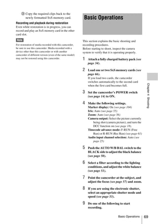
NTSC Area
3 Press the MENU knob or the SET
button.
Settings area This confirms the setting.
• The settings area displays a maximum of To cancel the setting change
seven lines. You can scroll through menus
Push the MENU CANCEL/PRST/ESCAPE
with more than seven sub-items by moving
switch down to the ESCAPE side.
the cursor up and down. Triangles appear at
the upper right and lower right of the
settings area to indicate that a sub-item To reset a setting to the initial value
menu is scrollable.
• For sub-items with a large settings range 1 Before a setting is changed or after a
(for example, –99 to +99), the settings area setting change is cancelled, push the
is not displayed. Instead, the sub-item name MENU CANCEL/PRST/ESCAPE
is highlighted to indicate that the sub-item switch up to the CANCEL/PRST side.
can be set.
2 When the message to confirm whether
5 Turn the MENU knob, or press the J or the current setting is reset to the initial
Chapter 6 Menu and Detailed Settings
j button, to select the value to set, and value, push the MENU CANCEL/
then confirm by pressing the MENU PRST/ESCAPE switch up to the
knob or the SET button. CANCEL/PRST side again.
The setting is changed, and the display is The current setting is reset to the initial value.
updated to show the new setting.
If you select [Execute] for an executable To exit the menu
item, the corresponding function is executed.
Set the MENU ON/OFF switch to OFF or press
Items that require confirmation before execution the MENU button.
In step 3, the menu disappears and a confirmation The normal camera picture reappears.
message appears if you select an item that
requires confirmation before execution. Follow
the instructions in the message to execute or
cancel the operation.
To enter text
Some items, such as time data or file names, must
be set by entering text. When you select one of
these items, the text entry area is highlighted, with
“SET” displayed to the right.
Basic Setup Menu Operations 97](https://image.slidesharecdn.com/pmw-320lenk-120216080013-phpapp02/85/Sony-PMW-320K-Operation-Manual-97-320.jpg)
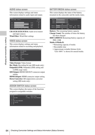
![Menu List
OPERATION Menu
Settings in bold are the factory default values.
OPERATION
Menu items Sub-item Settings Description
Format HD/SD HD/SD Switches between HD or SD as the
Specifies the operating mode (execute by
camcorder’s operating selecting Execute).
mode and recording
HD System Line 1080/720 When the operating mode is HD,
format.
sets the number of system lines to
1080 or 720 (execute by selecting
Execute).
System Frequency The available settings Selects the system frequency
vary depending on the (execute by selecting Execute).
settings in HD/SD, HD
System Line, and
Country.
59.94i/29.97P/23.98P When the HD/SD setting is [HD],
the HD System Line setting is
[1080], and the Country setting is
other than [PAL Area].
59.94P/29.97P/23.98P When the HD/SD setting is [HD],
the HD System Line setting is [720],
and the Country setting is other than
Chapter 6 Menu and Detailed Settings
[PAL Area].
59.94i/29.97P When the HD/SD setting is [SD],
and the Country setting is other than
[PAL Area].
50i/25P • When the HD/SD setting is [HD], the
HD System Line setting is [1080],
and the Country setting is [PAL
Area].
• When the HD/SD setting is [SD], and
the Country setting is [PAL Area].
50P/25P When the HD/SD setting is [HD],
the HD System Line setting is [720],
and the Country setting is [PAL
Area].
98 Menu List](https://image.slidesharecdn.com/pmw-320lenk-120216080013-phpapp02/85/Sony-PMW-320K-Operation-Manual-98-320.jpg)
![OPERATION
Menu items Sub-item Settings Description
Format Rec Format The available settings Selects the recording format
Specifies the vary depending on the (execute by selecting Execute).
camcorder’s operating settings in HD/SD, HD
mode and recording System Line, and System
format.
Frequency.
HQ 1920/HQ 1440 When the HD/SD setting is [HD],
the HD System Line setting is
[1080], and the System Frequency
setting is [29.97P] or [25P].
HQ 1920/HQ 1440/ When the HD/SD setting is [HD],
SP 1440 the HD System Line setting is
[1080], and the System Frequency
setting is other than [29.97P] and
[25P].
HQ 1280 When the HD/SD setting is [HD],
and the HD System Line setting is
[720].
DVCAM When the HD/SD setting is [SD].
Aspect Ratio (SD) 16:9/4:3 Selects the aspect ratio when SD
mode (recording format: DVCAM)
is selected (execute by selecting
Execute).
Country NTSC Area/NTSC(J) Selects the area of use (execute by
Area/PAL Area selecting Execute).
Format Media Media(A) Execute/Cancel Initializes the SxS memory card in
Executes a media slot A (execute by selecting
format. Execute).
Media(B) Execute/Cancel Initializes the SxS memory card in
slot B (execute by selecting
Chapter 6 Menu and Detailed Settings
Execute).
Menu List 99](https://image.slidesharecdn.com/pmw-320lenk-120216080013-phpapp02/85/Sony-PMW-320K-Operation-Manual-99-320.jpg)
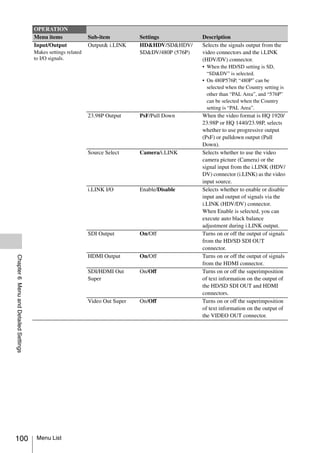
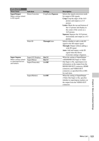
![OPERATION
Menu items Sub-item Settings Description
Rec Function Slow & Quick On/Off Turns the Slow & Quick Motion
Makes settings related function on or off. (When this is set
to special recording to On, the Picture Cache Rec,
modes. Interval Rec, and Frame Rec sub-
Note items are set to Off.)
When Picture Cache is Frame Rate The available settings When the Slow & Quick setting is
assigned to an vary depending on the On, sets the frame rate for Slow &
assignable switch, this Format >HD System Line Quick Motion shooting.
item is disabled setting.
(displayed in grey).
When Format >Country When the HD System Line setting is
is set to other than [PAL 1080.
Area]: 1 to 30
When Format >Country
is set to [PAL Area]: 1 to
25 to 30
When Format >Country When the HD System Line setting is
is set to other than [PAL 720.
Area]: 1 to 30 to 60
When Format >Country
is set to [PAL Area]: 1 to
25 to 60
Picture Cache Rec On/Off Turns the picture cache function on
or off. (When this is set to On, the
Slow & Quick, Interval Rec, Frame
Rec sub-items are set to Off.)
P. Cache Rec Time 0-2sec/2-4sec/4-6sec/ When the Picture Cache Rec setting
6-8sec/8-10sec/10-12sec/ is On, set the picture cache time.
12-14sec/13-15sec
Interval Rec On/Off Turns the Interval Rec function on or
Chapter 6 Menu and Detailed Settings
off. (When this is set to On, the Slow
& Quick, Picture Cache Rec, and
Frame Rec sub-items are set to Off.)
Frame Rec On/Off Turns the Frame Rec function on or
off. (When this is set to On, the Slow
& Quick, Picture Cache Rec, and
Interval Rec sub-items are set to
Off.)
Number of Frames The available settings When Interval Rec or Frame Rec is
vary depending on the set to On, specifies the number of
settings in Format >HD frames to shoot in one Interval Rec
System Line and Format or Frame Rec take.
>System Frequency.
2frame/6frame/12frame When the HD System Line setting is
720, and the System Frequency
setting is 59.94P or 50P.
1frame/3frame/6frame/ When the HD System Line setting is
9frame other than 720, or the System
Frequency setting is other than
59.94P or 50P.
102 Menu List](https://image.slidesharecdn.com/pmw-320lenk-120216080013-phpapp02/85/Sony-PMW-320K-Operation-Manual-102-320.jpg)
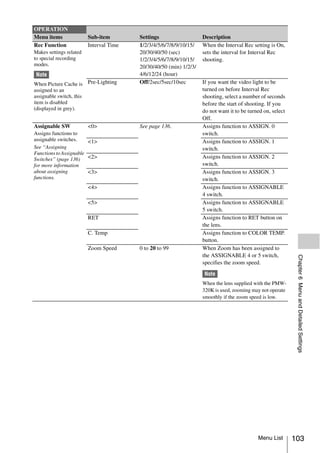
![OPERATION
Menu items Sub-item Settings Description
VF Setting Color –99 to ±0 to +99 Adjusts the density of the colors
Makes settings related displayed in the viewfinder screen.
to the viewfinder Mode Color/B&W Selects Color or B&W as the display
screen.
mode of the viewfinder screen.
(Even when B&W is selected, some
indications are always displayed in
color. Examples include tally
indications, thumbnails, and the skin
gate area.)
Peaking Type Normal/Color/Both Selects the peaking type.
Normal: Normal peaking
Color: Color peaking
Both: Both
Peaking Frequency Normal/High Selects Normal or High as the
peaking frequency.
Peaking Color White/Red/Yellow/Blue When the Peaking Type setting is
Color, selects the peaking color from
among White, Red, Yellow, and
Blue.
Peaking Level Low/Mid/High When the Peaking Type setting is
Both, selects the color peaking level
from among Low, Mid, and High.
DXF Rec Tally Upper/Both When a separately sold viewfinder is
installed, specified whether to light
the tally indicator on the upper side
only (Upper), or on both the upper
and lower sides (Both).
Marker Setting On/Off Turns all markers on or off.
Makes settings related
Chapter 6 Menu and Detailed Settings
to marker display in the Note
viewfinder screen. When Marker is assigned to the
ASSIGN. 2 switch, this setting is
disabled.
Center Marker 1/2/3/4/Off When the center marker is
displayed, selects the type. Select
Off if you do not want to display the
marker.
Note
When Safety Zone, User Box, and
Guide Frame are set to [On], this
setting cannot be turned on.
Center H Position –40 to 0 to 40 Specifies the horizontal position of
the center marker.
Center V Position –40 to 0 to 40 Specifies the vertical position of the
center marker.
104 Menu List](https://image.slidesharecdn.com/pmw-320lenk-120216080013-phpapp02/85/Sony-PMW-320K-Operation-Manual-104-320.jpg)
![OPERATION
Menu items Sub-item Settings Description
Marker Safety Zone On/Off Turns the safety zone display on or
Makes settings related off.
to marker display in the
viewfinder screen. Note
When Center Marker, User Box, and
Guide Frame are set to [On], this
setting cannot be turned on.
Safety Area 80%/90%/92.5%/95% Selects the safety zone range.
Aspect Marker Line/Mask/Off When an aspect marker is to be
displayed, selects the display
method. Select Off if you do not
want to display the marker.
Line: Show as white lines.
Mask: Display by lowering the
video signal level of areas
outside the marker range.
Aspect Select 15:9/14:9/13:9/4:3/ Selects the aspect ratio of the
1.66:1/1.85:1/2.35:1/ marker.
2.4:1
Aspect Mask 0% to 30% to 90% (10% When the Aspect Marker setting is
step) Mask, specifies the video signal
level of areas outside the marker
range as a percentage value relative
to the video signal level of areas
inside the marker range.
User Box On/Off Turns the box cursor display on or
off.
Note
Chapter 6 Menu and Detailed Settings
When Center Marker, Safety Zone,
and Guide Frame are set to [On],
this setting cannot be turned on.
User Box Width 40 to 500 to 999 Specifies the box cursor width
(distance from the center to the left
and right edges).
User Box Height 70 to 500 to 999 Specifies the box cursor height
(distance from the center to the top
and bottom edges).
User Box H Position –479 to 0 to 479 Specifies the horizontal position of
the box cursor center.
User Box V Position –464 to 0 to 464 Specifies the vertical position of the
box cursor center.
Guide Frame On/Off Turns display of the guide frame on
or off.
Note
When Center Marker, Safety Zone,
and User Box are set to [On], this
setting cannot be turned on.
Menu List 105](https://image.slidesharecdn.com/pmw-320lenk-120216080013-phpapp02/85/Sony-PMW-320K-Operation-Manual-105-320.jpg)
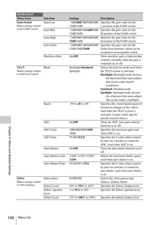
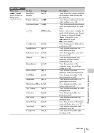
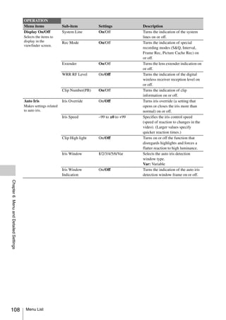
![OPERATION
Menu items Sub-item Settings Description
White Setting White Switch<B> Memory/ATW Specifies the operating mode
Makes settings related selected by the B position of the
to auto white balance WHITE BAL switch.
adjustments. Memory: Auto white balance
ATW: Auto tracing white balance
Shockless White Off/1/2/3 Specifies the reaction speed when
the WHITE BAL switch setting is
changed. Off is an instant reaction,
and 1 is faster than 2 or 3.
ATW Speed 1/2/3/4/5 Specifies the reaction speed when
the White Switch<B> setting is
[ATW]. 1 is the fastest reaction.
AWB Fixed Area On/Off Specifies whether auto white
balance is executed at the center of
the screen.
On: Execute in an area
corresponding to 25% of the
height and width of the screen.
Off: Execute in an area
corresponding to 70% of the
height and width of the screen.
Filter White Memory On/Off Specifies whether to allocate a white
balance memory area for each
FILTER knob position.
On: Allocation a white balance
memory area for each FILTER
knob position.
Off: Use A/B memory regardless of
the filter position.
Chapter 6 Menu and Detailed Settings
Menu List 109](https://image.slidesharecdn.com/pmw-320lenk-120216080013-phpapp02/85/Sony-PMW-320K-Operation-Manual-109-320.jpg)
![OPERATION
Menu items Sub-item Settings Description
Offset White Offset White <A> On/Off Specifies whether to add (On) or not
Makes settings related to add (Off) an offset value to the
to white balance offset white balance value in memory A.
values.
Warm Cool <A> Approximate color When the setting of Offset
temperature White<A> is [On], specifies (as a
color temperature) the offset to add
to the white balance value in
memory A. (Note that the error
range becomes larger for higher
offset color temperatures. Adjust
while viewing the actual video.)
Warm Cool –99 to ±0 to +99 Specifies a more precise color
Balance<A> temperature, for use when
satisfactory video cannot be
obtained with the Warm Cool <A>
setting.
Offset White <B> On/Off When this is set to [On], the offset
adjusted set with this item is added
to the white balance of channel B.
Warm Cool <B> Approximate color When the setting of Offset
temperature White<B> is [On], specifies (as a
color temperature) the offset to add
to the white balance value in
memory B. (Note that the error
range becomes larger for higher
offset color temperatures. Adjust
while viewing the actual video.)
Warm Cool –99 to ±0 to +99 Specifies a more precise color
Balance<B> temperature, for use when
Chapter 6 Menu and Detailed Settings
satisfactory video cannot be
obtained with the Warm Cool <B>
setting.
Shutter Select Shutter Select Second/Degree Specifies the unit used to select
Makes settings related shutter speeds.
to shutter speed Second: Select in units of seconds.
selection. Degree: Select in units of degrees.
Time Zone Zone –12:00 to +0:00 to Specifies a difference from UTC
Specifies the time zone. +14:00 (in steps of (Greenwich Mean Time) in units of
30 minutes) 30 minutes.
Clip Auto Naming Title/Plan Selects the clip naming format.
Make settings for clip Title: Name specified by Title Prefix
name or clip Plan: Name specified in planning
management. metadata (if no name is
Note specified in planning metadata,
Do not assign clip
the name specified by Title
names that begin with Prefix is selected.)
the “.” (period) symbol.
Clips with names in
which the first
character is “.” cannot
be viewed on the
application software for
computers.
110 Menu List](https://image.slidesharecdn.com/pmw-320lenk-120216080013-phpapp02/85/Sony-PMW-320K-Operation-Manual-110-320.jpg)
![OPERATION
Menu items Sub-item Settings Description
Clip Title Prefix Text input Specifies the title part (4 to 46
Make settings for clip alphanumeric characters) of clip
name or clip titles.
management. When the currently specified title is
Note eight characters or fewer in length,
Do not assign clip
the entire title appears. When the
names that begin with title is longer than eight characters,
the “.” (period) symbol. the first seven characters appear and
Clips with names in a “···” symbol appears in place of the
which the first eighth character.
character is “.” cannot
Displays the Character Set screen.
be viewed on the
application software for Character Set screen configuration
computers. • Character selection area (three
lines)
Select the character to insert at the
title prefix cursor position.
!#$%()+.-.;=@[]^_~0123456789
abcdefghijklmnopqrstuvwxyz
ABCDEFGHIJKLMNOPQRSTUV
WXYZ
• Cursor operation area (one line)
Space: Changes the character at the
cursor position to a space
INS: Inserts a space at the cursor
position
DEL: Deletes the character at the
cursor position
T: Moves the cursor to the left
t: Moves the cursor to the right
Chapter 6 Menu and Detailed Settings
ESC: Cancels the change and return
to the normal menu
END: Executes the change and
return to the normal menu
• Title prefix area (one line)
An area to enter the title
To set titles
1 Turn the MENU knob or press the
arrow buttons to select a
character, highlighting it, in the
character selection area, and then
press the MENU knob or the SET
button to insert it at the cursor
position in the title prefix area.
(The cursor moves to the right.)
2 Repeat step 1 to add more
characters to the title (using
Space, INS, and DEL as
required).
3 When you have finished entering
the title, select END to close the
Character Set screen.
Menu List 111](https://image.slidesharecdn.com/pmw-320lenk-120216080013-phpapp02/85/Sony-PMW-320K-Operation-Manual-111-320.jpg)
![OPERATION
Menu items Sub-item Settings Description
Clip Number Set 0001 to 9999 Specifies the initial value of the
Make settings for clip numeric part (four digits) of clip
name or clip names (unless the name specified in
management. planning metadata with Auto
Note Naming set to [Plan]).
Do not assign clip Name Display Off/On Selects whether to display the name
names that begin with of the next clips to be recorded in E-
the “.” (period) symbol. E mode (On) or not (Off).
Clips with names in Update Media<A>/Media<B> Updates the management files on the
which the first
character is “.” cannot
media in the selected slot (execute
be viewed on the by selecting Execute).
application software for
computers.
Plan.Metadata Load/Slot(A) Execute/Cancel Executes load of planning metadata
Makes settings for from the SxS memory card in slot A.
operating planning Select [Execute] to show the list of the
metadata. planning metadata files stored in the
slot A SxS memory card and select a
file to execute the load.
Load/Slot(B) Execute/Cancel Executes load of planning metadata
from the SxS memory card in slot B.
Select [Execute] to show the list of
the planning metadata files stored in
the slot B SxS memory card and
select a file to execute the load.
Properties Execute/Cancel Displays the detailed information in
the planning metadata loaded on the
camcorder (execute by selecting
[Execute]).
Clear Execute/Cancel Clears the planning metadata loaded
Chapter 6 Menu and Detailed Settings
on the camcorder (execute by
selecting [Execute]).
Clip Name Disp Title1(ASCII) Selects the display mode of the clip
Title2(UTF-8) name specified in planning metadata
(see page 80).
112 Menu List](https://image.slidesharecdn.com/pmw-320lenk-120216080013-phpapp02/85/Sony-PMW-320K-Operation-Manual-112-320.jpg)
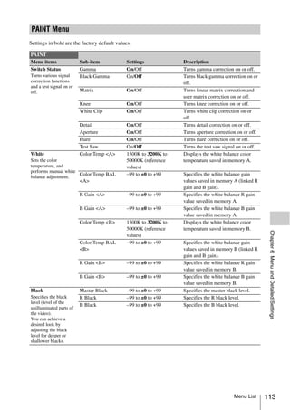
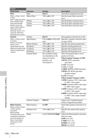
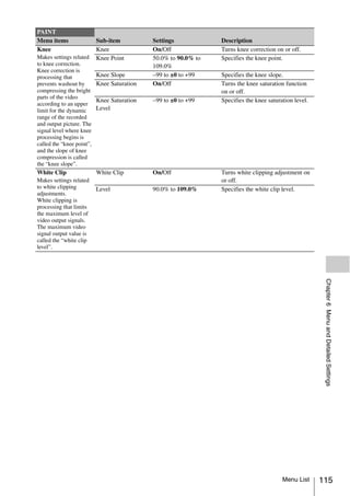
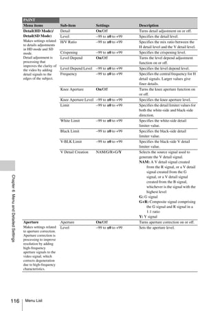
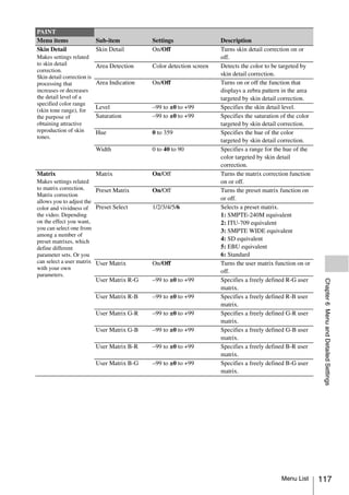
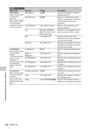
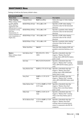
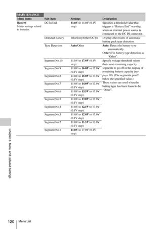
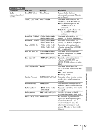
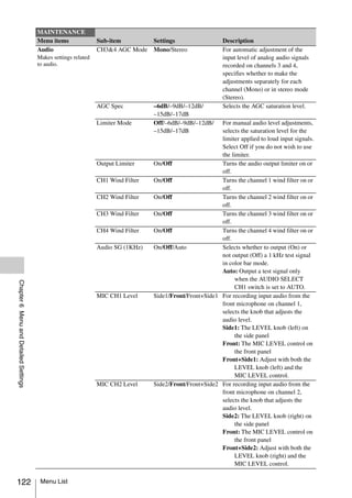
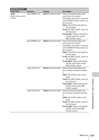
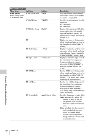
![MAINTENANCE
Menu items Sub-item Settings Description
Timecode TC Out Auto/Generator Selects the source for timecode
Makes settings related output.
to timecode. Auto: During recording, output
values generated by the
timecode generator, and during
playback output values
obtained by the timecode
reader.
Generator: Output values
generated by the timecode
generator during both recording
and playback.
DF/NDF DF/NDF When the Country setting is other
than [PAL Area], selects drop-frame
mode (DF) or non-drop-frame mode
(NDF).
LTC UBIT Fix/Time Specifies the data recorded in LTC
user bits.
Fix: Record user-specified data.
Time: Record the current time.
Counter Display Counter/Duration Select the method used to reset the
counter value displayed on the
viewfinder screen.
Counter: Continue to increment
until the RESET button is
pressed.
Duration: Reset each time that
recording is started.
Essence Mark Ret Shot Mark 1 On/Off Specify whether to input Shot
Chapter 6 Menu and Detailed Settings
Makes settings related Mark1 marks using the RET button
to shot marks and clip on the lens.
index picture
thumbnails.
Ret Shot Mark 2 On/Off Specify whether to input Shot
Mark2 marks using the RET button
on the lens.
Menu List 125](https://image.slidesharecdn.com/pmw-320lenk-120216080013-phpapp02/85/Sony-PMW-320K-Operation-Manual-125-320.jpg)
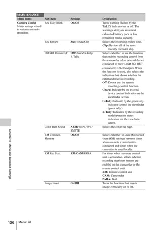
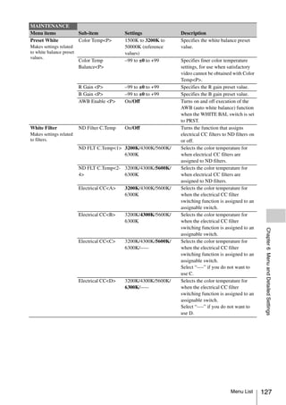
![MAINTENANCE
Menu items Sub-item Settings Description
Auto Iris2 Iris Window 1/2/3/4/5/6/Var Selects the type of iris detection
Makes settings related window.
to auto iris. Var: Variable
Iris Window Ind On/Off Turns on or off the function that
displays a frame marker for the auto
iris detection window.
Iris Level –99 to ±0 to +99 Adjusts the level of the auto iris
target value.
Iris APL Ratio –99 to ±0 to +99 Adjusts the mix ratio of auto iris
detection peak value and average
value (available when OPERATION
>TLCS >Mode is set to [Standard]).
Iris Var Width 40 to 500 to 999 Adjusts the width of the detection
window when the setting of Iris
Window is VAR.
Iris Var Height 70 to 500 to 999 Adjusts the height of the detection
window when the setting of Iris
Window is VAR.
Iris Var H Position –249 to 0 to +249 Specifies the horizontal position of
the detection window when the
setting of Iris Window is VAR.
Iris Var V Position –249 to 0 to +249 Specifies the vertical position of the
detection window when the setting
of Iris Window is VAR.
Iris Speed –99 to ±0 to +99 Specifies the control speed (speed of
reaction to changes in the video).
(Larger values specify quicker
reaction times.)
Clip High Light On/Off Turns on or off the function that
Chapter 6 Menu and Detailed Settings
disregards highlights and forces a
flatter reaction to high luminance.
Flicker Reduce Mode Auto/On/Off Enables or disables flicker
Makes settings related reduction.
to flicker reduction. On: Always enabled.
Reduces the flicker that Auto: Enabled when flicker is
can occur when a
subject is shot under a detected.
light source with a Off: Disabled
periodically varying Frequency 60Hz/50Hz Set to the frequency of the lighting
brightness, such as fixture that is causing the flicker.
fluorescent lights, due
(The factory default setting is 50 Hz
to the relationship with
the camcorder’s when the Country setting is
recording frame rate. “PAL Area”, 60 Hz when it is other
than “PAL Area”.)
Genlock H Phase(HD) –999 to ±0 to +999 Specifies the H phase of HD output
Makes settings related when genlock is enabled.
to genlock. H Phase(SD) –99 to ±0 to +99 Specifies the H phase of SD output
when genlock is enabled.
Reference Internal/Genlock Displays the type of reference signal
used by the camcorder.
128 Menu List](https://image.slidesharecdn.com/pmw-320lenk-120216080013-phpapp02/85/Sony-PMW-320K-Operation-Manual-128-320.jpg)
![MAINTENANCE
Menu items Sub-item Settings Description
ND Comp ND Offset Adjust On/Off ND filter color compensation
Makes settings related function.
to ND filter color Clear ND Offset Execute/Cancel Clears ND filter color compensation
compensation.
Although the
values (execute by selecting
differences are very Execute).
slight, each of the built-
in ND filters has
different color
characteristics. When
you switch between ND
filters, the white
balance may be
disturbed. You can
correct for these slight
color differences
automatically by
registering
compensation values
for each filter.
Lens Auto FB Adjust Execute/Cancel Executes auto flange back
Executes auto flange adjustment, only for supported
back adjustment. lenses (execute by selecting
Execute).
Trigger Mode i.LINK Trigger Internal/Both/External Select Internal when recording start
Makes settings related Mode and stop operations target SxS
to triggers for starting memory cards only. Select External
and stopping recording. when they target only devices
connected to the i.LINK (HDV/DV)
or HD/SD SDI OUT connectors.
Select Both when they target both
memory cards and external devices.
Chapter 6 Menu and Detailed Settings
Network Setting a) DHCP Enable/Disable Selects whether to acquire the IP
Makes settings for address automatically from a DHCP
network connection. server (Enable) or not (Disable).
IP Address 0.0.0.0 to When DHCP is set to [Disable], sets
Notes
255.255.255.255 the IP address.
• The CBK-WA01 (192.168.1.10)
Wi-Fi Adapter is Subnet Mask 0.0.0.0 to When DHCP is set to [Disable], sets
required. 255.255.255.255 the subnet mask.
• This item is
Default Gateway 0.0.0.0 to When DHCP is set to [Disable], sets
disabled (displayed
255.255.255.255 the default gateway.
in grey) during
User Name admin Sets a desired user name in 1 to 31
recording and play.
alphanumeric characters.
For details on Password pmw-320 (model name) Sets a password (model name) in 0
network connection, to 31 alphanumeric characters.
refer to the
Set Execute/Cancel Confirms the settings in Network
Supplement supplied
Settings (execute by selecting
in the CD-ROM
[Execute]).
(labeled “Manuals for
MAC Address Displays the MAC address.
Solid-State Memory
Camcorder”). Net Config Reset Execute/Cancel Resets the settings in Network
Settings to the preset values
(execute by selecting [Execute]).
Menu List 129](https://image.slidesharecdn.com/pmw-320lenk-120216080013-phpapp02/85/Sony-PMW-320K-Operation-Manual-129-320.jpg)
![MAINTENANCE
Menu items Sub-item Settings Description
Wi-Fi Setting a) Scan Networks Execute/Cancel When Wi-Fi is set to [Enable], scan
Makes settings for the available network connection.
Wi-Fi connection. SSID Network connection Sets the network connection name
name of up to 32 characters.
Notes
Network Type Infra/Adhoc Selects the connection mode.
• The CBK-WA01 Infra: Infrastructure mode
Wi-Fi Adapter is Adhoc: Ad hoc mode
required.
Ch 1 to 11 When Network Type is set to
• This item is
[Adhoc], set the wireless channel.
disabled (displayed
Authentication Open/Shared/WPA/ Selects the network authentication.
in grey) during
WPA2 OPEN: Open system authentication
recording and play.
SHARED: Shared key
For details on Wi-Fi authentication
connection, refer to WPA: WPA (Wi-Fi Protected
the Supplement Access) authentication
supplied in the CD- WPA2: WPA2 (Wi-Fi Protected
ROM (labeled Access 2) authentication
“Manuals for Solid- Encryption Disable/WEP/TKIP/AES Selects whether to apply data
State Memory encryption and the type of data
Camcorder”). encryption.
Disable: Do not apply data
encryption.
WEP: Apply WEP (Wired
Equivalent Privacy) when
Authentication is set to [Open]
or [Shared]
TKIP: Apply TKIP (Temporal Key
Integrity Protocol) when
Authentication is set to [WPA]
Chapter 6 Menu and Detailed Settings
or [WPA2]
AES: Apply AES (Advanced
Encryption Standard) when
Authentication is set to [WPA]
or [WPA2]
WEP Key Index 1/2/3/4 When Encryption is [WEP], selects
the key index.
Input Select When Encryption is set to Selects the input format depending
[WEP]: ASCII5, on the network key (or security key).
ASCII13, HEX10, ASCII5: Five characters ASCII
HEX26 format
When Encryption is set to ASCII13: 13 characters ASCII
[TKIP] or [AES]: format
ASCII8-63, HEX64 HEX10: 10 hexadecimal digits
HEX26: 26 hexadecimal digits
ASCII8-63: 8 to 63 characters
ASCII 8-bit format
HEX64: 64 hexadecimal digits
(characters)
Key Sets the network key (or security
key).
130 Menu List](https://image.slidesharecdn.com/pmw-320lenk-120216080013-phpapp02/85/Sony-PMW-320K-Operation-Manual-130-320.jpg)
![MAINTENANCE
Menu items Sub-item Settings Description
Wi-Fi Setting a) Set Enables settings for Wi-Fi Setting
Makes settings for when Wi-Fi is set to [Enable]
Wi-Fi connection. (execute by selecting [Execute]).
Wi-Fi Status xxxxx Displays “Connecting” while
Notes
Connecting connection is being attempted.
• The CBK-WA01 Displays black squares to show the
Wi-Fi Adapter is connection status by the number of
required. squares when the camcorder is
• This item is connected to a computer or a LAN.
disabled (displayed Wireless Mode 802.11b/802.11g/802.11n Displays an IEEE802.11 standard.
in grey) during
Wi-Fi Enable/Disable Selects whether to enable or disable
recording and play.
Wi-Fi connection.
For details on Wi-Fi
connection, refer to
the Supplement
supplied in the CD-
ROM (labeled
“Manuals for Solid-
State Memory
Camcorder”).
Clock Set Date/Time Sets the current date and time.
Sets the internal clock. 12H/24H 12H/24H Selects the 12-hour format (12H) or
the 24-hour format (24H) for
display of times.
Date Mode YYMMDD/MMDDYY/ Selects the display format for dates.
DDMMYY YYMMDD: Year, Month, Day
MMDDYY: Month, Day, Year
DDMMYY: Day, Month Year
Language Language English/Chinese Selects the language for messages
Chapter 6 Menu and Detailed Settings
Selects the language for from English or Chinese.
messages.
Hours Meter Hours(Sys) Displays the cumulative hours of
Makes settings related use (cannot be reset).
to the digital hours Hours(Reset) Displays the hours of use (can be
meter.
reset).
Reset Execute/Cancel Resets Hours(Reset) to 0.
(Execute by selecting Execute.)
Version Version Displays the software version of the
Displays the version of camcorder (Vx.xx).
the camcorder, and Version Up Execute/Cancel Updates the camcorder (execute by
updates the camcorder.
selecting Execute).
Note
This cannot be selected unless an SxS
memory card is inserted.
a) When the optional CBK-UPG02 is installed.
Menu List 131](https://image.slidesharecdn.com/pmw-320lenk-120216080013-phpapp02/85/Sony-PMW-320K-Operation-Manual-131-320.jpg)
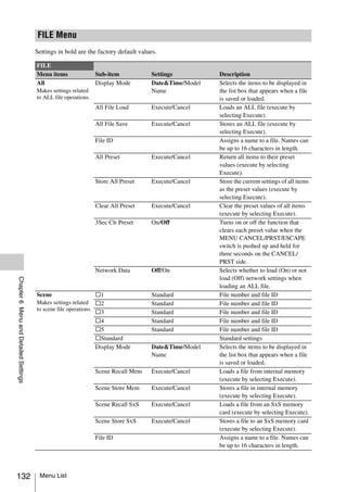
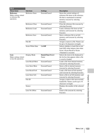
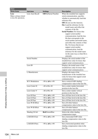
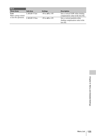
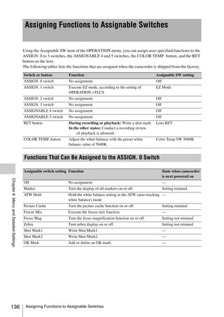
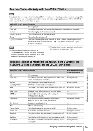
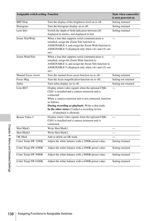
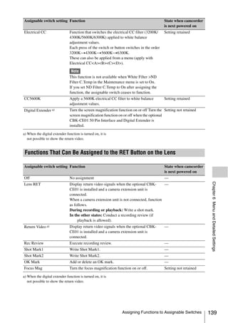
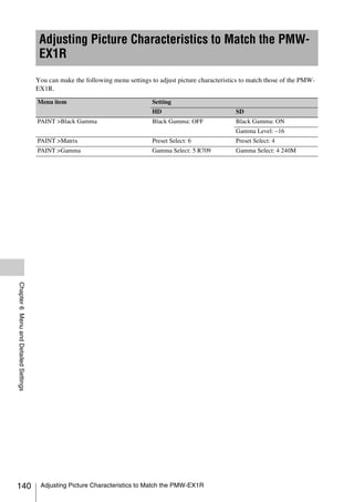
![7 Saving and Loading User Setting Data
Chapter 7 Saving and Loading User Setting Data
Chapter
Saving Setting Data
Saving and Loading
Settings This section explains how to save setting data in
an ALL file.
Before starting, insert a writable SxS memory
card into a memory card slot.
See “Basic Setup Menu Operations” (page 96) for
You can save setup menu settings in the
information about menu operations.
camcorder’s internal memory and on SxS
memory cards. This allows you to quickly recall 1 Select FILE >All in the setup menu.
an appropriate set of menu settings for the current
situation. To assign a name to the data before saving
Setting data is saved in the following categories. it
ALL files: ALL files save the setting data of all Assign a name before proceeding to step 2.
menus. You can save up to 64 ALL files on
an SxS memory card. For details, see “To assign names to files”
(page 142).
Note
Device specific data (shading, output levels, and 2 Select All File Save >Execute.
other data that requires adjustment for the specific An ALL file list box appears.
device) is not saved. File numbers where “No File” is displayed
Scene files: Scene file save adjustments to are empty file numbers. File numbers with a
PAINT menu items for the purpose of file name or a date and time are the number
shooting a particular scene. You can save up of files that already contain data.
to five scene files in the camcorder’s internal
memory and up to 64 scene files on an SxS 3 Turn the MENU knob to select the
memory card. desired file number.
Reference files: Reference files save the
reference values that are set when you 4 Press the MENU knob.
execute FILE >Scene > Standard in the setup A confirmation message appears.
menu. You can save one reference file in the
camcorder’s internal memory and one on an
5 To execute the save, select [Execute],
and then press the MENU knob.
SxS memory card.
Lens files: Lens files save the setting data used to To cancel the save, select [Cancel], and
compensate for lens characteristics, such as then press the MENU knob.
flare, white shading, white balance and If you choose to execute the save, the
center markers. You can save up to 32 lens ACCESS lamp lights (in blue on the right-
files in the camcorder’s internal memory and side panel and in orange in the card slot
up to 64 lens files on an SxS memory card. section). A completion message appears and
the ACCESS lamp goes out when the data
The first settings stored in a file are called has been saved to the SxS memory card.
“preset” values. If an error message appears
Even after loading files to set up the camcorder, One of the following error messages may appear
and overwriting original files with new settings, during execution of the save, or as soon as you
you can still recover preset values and reset files select [Execute]. In this case, the file is not saved
to their initial states (see page 142). to the SxS memory card.
Saving and Loading Settings 141](https://image.slidesharecdn.com/pmw-320lenk-120216080013-phpapp02/85/Sony-PMW-320K-Operation-Manual-141-320.jpg)
![3 Turn the MENU knob to select the
Error message Problem What to do
desired file number.
Chapter 7 Saving and Loading User Setting Data
NG:Cannot Save No recordable Insert
media is recordable 4 Press the MENU knob.
inserted. media. A confirmation message appears.
NG:Media Full The media is Use media with
full. free capacity 5 To execute the load, select [Execute],
remaining. and then press the MENU knob.
To cancel the load, select [Cancel], and
To assign names to files then press the MENU knob.
Assigning a name before you save data in an ALL If you choose to execute the load, the
file can make it easier to distinguish your files. ACCESS lamp lights (in blue on the right-
The following characters can be used in file side panel and in orange in the card slot
names. section). The ACCESS lamp goes out and a
Alphanumeric characters (a–z, A–Z, 0–9) and completion message appears when the data
special characters ( ! # $ % & ' ( ) * + , - . / : ; < = has been loaded from the SxS memory card.
> ? @ [ ] ~) If an error message appears
One of the following error messages may appear
1 Select FILE >All >File ID in the setup
during execution of the load, or as soon as you
menu.
select [Execute]. In this case, the file is not loaded
2 Turn the MENU knob to select a from the SxS memory card.
character, and then press the MENU Error message Problem What to do
knob. NG:No Data • There is no Insert the
readable media media that
3 Repeat step 3. • The specified contains the
file does not file you want.
4 When you have finished entering exist on the
characters, press the MENU knob to media
move the cursor to “SET”, and then
press the MENU knob. Resetting a File after Changing Its
The specified name is displayed. Contents
When you save the file (see page 141), the
data will be saved under this name. See “Basic Setup Menu Operations” (page 96) for
information about menu operations.
Loading Setting Data 1 Select FILE >All in the setup menu.
Note 2 Select [All Preset], and then press the
When you load a file from an SxS memory card, the data MENU knob.
saved in the camcorder’s internal memory is overwritten.
See “Basic Setup Menu Operations” (page 96) for
3 To execute the reset, select [Execute],
information about menu operations. and then press the MENU knob.
To cancel the reset, select [Cancel], and
1 Select FILE >All in the setup menu. then press the MENU knob.
If you choose to execute the reset, all settings
2 Select All File Load >Execute. in the ALL file are reset to preset values.
A list box of ALL files appears.
File numbers where “No File” is displayed
are empty file numbers. File numbers with a
file name or a date and time are the number
of files that already contain data.
142 Saving and Loading Settings](https://image.slidesharecdn.com/pmw-320lenk-120216080013-phpapp02/85/Sony-PMW-320K-Operation-Manual-142-320.jpg)
![5 To execute the save, select [Execute],
Saving and Loading and then press the MENU knob.
Chapter 7 Saving and Loading User Setting Data
To cancel the save, select [Cancel], and
Scene Files then press the MENU knob.
If you selected Scene Store SxS in step 2, the
ACCESS lamp lights when you execute the
save (in blue on the right-side panel and in
Scene files allow you to save the following types orange in the card slot section).
of data. When the data has been saved to the SxS
• Values set in the PAINT menu memory card, a completion message appears
• Shutter speeds set in standard mode or ECS and the ACCESS lamp goes out.
mode
• White balance data
The data that is saved and loaded depends on the Loading Scene Files
setting of FILE >Reference >Scene White Data
To load a scene file from an SxS memory card,
in the setup menu.
insert the SxS memory card into a memory card
slot, and then proceed as follows.
Saving Scene Files See “Basic Setup Menu Operations” (page 96) for
information about menu operations.
To save a scene file to an SxS memory card, insert
the card into a memory card slot and then proceed 1 Select FILE >Scene in the setup menu.
as follows.
See “Basic Setup Menu Operations” (page 96) for
2 Select Scene Recall Mem or Scene
information about menu operations. Recall SxS.
Select Scene Recall Mem if you want to load
1 Select FILE >Scene in the setup menu. the file from the camcorder’s internal
memory, and select Scene Recall (SxS) if
To assign a name to the data before saving you want to load the file from an SxS
it memory card.
Assign a name before proceeding to step 2.
3 Press the MENU knob.
For details, see “To assign names to files”
A list box of scene files appears. File
(page 142).
numbers where “No File” is displayed are
2 Select Scene Store Mem or Scene Store empty file numbers.
SxS.
Select Scene Store Mem if you want to save
4 Select the desired file number, and then
press the MENU knob.
the data in the camcorder’s internal memory,
A confirmation message appears.
and select Scene Store SxS if you want to
save the data on an SxS memory card. 5 To execute the load, select [Execute],
and then press the MENU knob.
3 Press the MENU knob.
To cancel the load, select [Cancel], and
A list box of scene files appears.
File numbers where “No File” is displayed
then press the MENU knob.
are empty file numbers If you selected Scene Recall SxS in step 2,
the ACCESS lamp lights when you execute
4 Select the file number under which you the load (in blue on the right-side panel and
want to save the data, and then press the in orange in the card slot section).
MENU knob. When the data has been loaded from the SxS
A confirmation message appears. memory card, a completion message appears
and the ACCESS lamp goes out.
Saving and Loading Scene Files 143](https://image.slidesharecdn.com/pmw-320lenk-120216080013-phpapp02/85/Sony-PMW-320K-Operation-Manual-143-320.jpg)
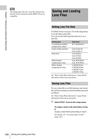
![2 Select Lens Store Mem or Lens Store To cancel the load, select [Cancel], and
SxS, and press the MENU knob. then press the MENU knob.
Chapter 7 Saving and Loading User Setting Data
Select Lens Store Mem if you want to save If you select [Execute], a list box of lens files
the data in the camcorder’s internal memory, appears. File numbers where “No File” is
and select Lens Store SxS if you want to save displayed are empty file numbers.
the data on an SxS memory card.
4 Select the desired file number, and then
3 To execute the save, select [Execute], press the MENU knob.
and then press the MENU knob. A confirmation message appears.
To cancel the save, select [Cancel], and
then press the MENU knob. 5 To execute the load, select [Execute],
If you select [Execute], a list box of lens file and then press the MENU knob.
number appears. File numbers where “No To cancel the load, select [Cancel], and
File” is displayed are empty file numbers. then press the MENU knob.
If you selected Lens Recall SxS in step 2, the
4 Select the file number under which you ACCESS lamp lights when you execute the
want to save the data, and then press the load (in blue on the right-side panel and in
MENU knob. orange in the card slot section).
A confirmation message appears. When the specified lens file has been loaded
from the SxS memory card, a completion
5 To execute the save, select [Execute], message appears and the ACCESS lamp goes
and then press the MENU knob. out.
To cancel the save, select [Cancel], and
then press the MENU knob.
If you selected Lens Store SxS in step 2, the Loading Lens Files Automatically
ACCESS lamp lights when you execute the
When you are using a lens that support serial
save (in blue on the right-side panel and in
communication, you can set up the camcorder by
orange in the card slot section).
automatically loading the lens file that
When the data has been saved to the SxS
corresponds to the lens settings (Lens Auto Recall
memory card, a completion message appears
function).
and the ACCESS lamp goes out.
To use the Lens Auto Recall function, set FILE
>Lens >Lens Auto Recall in the setup menu to
Loading Lens Files one of the following.
On: Load the lens file that corresponds to the
To load a lens file from an SxS memory card, model name.
insert the SxS memory card into a memory card Off: Do not use the Lens Auto Recall function.
slot, and then proceed as follows. Serial Number: Load the lens file that
See “Basic Setup Menu Operations” (page 96) for corresponds to the model name and serial
information about menu operations. number (when the lens supports
communication of the serial number).
1 Select FILE >Lens in the setup menu. If the lens does not support communication of the
serial number, both settings load the lens file that
2 Select Lens Recall Mem or Lens Recall corresponds to the model name.
SxS, and press the MENU knob.
Select Lens Recall Mem if you want to load
the file from the camcorder’s internal
memory, and select Lens Recall SxS if you
want to load the file from an SxS memory
card.
3 To execute the load, select [Execute],
and then press the MENU knob.
Saving and Loading Lens Files 145](https://image.slidesharecdn.com/pmw-320lenk-120216080013-phpapp02/85/Sony-PMW-320K-Operation-Manual-145-320.jpg)
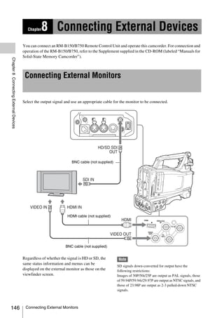
![HD/SD SDI OUT connector (BNC) i.LINK (HDV/DV) connector
The HD/SD SDI OUT connector can be used to The i.LINK (HDV/DV) connector supports HDV
connect a device that supports SDI. The device and DV input/output. However, DV streams
type can be a monitor, switcher, or VTR or other cannot be recorded on this camcorder.
recording device. This connector can be used to connect a device
The output from this connector can be turned on that supports i.LINK (HDV). The device type can
and off with OPERATION >Input/Output >SDI be a monitor, read/write device such as VTR or
Chapter 8 Connecting External Devices
Output in the setup menu (see page 100). HDD, or computer.
For connection, use a BNC cable (not supplied).
To input/output HDV signals
HDV input/output is supported when the video
HDMI connector format is an HDV compatible format (SP 1440/
The HDMI connector can be used to connect a 59.94i, SP 1440/50i, or SP 1440/23.98P), Input/
device that supports HDMI. The device type can Output >Output&i.LINK in the OPERATION
be a monitor or VTR or other recording device. menu is set to [HD&HDV] or [SD&HDV], and
The output from this connector can be turned on Input/Output >i.LINK I/O is set to [Enable].
and off with OPERATION >Input/Output When the video format is SP 1440/23.98P, a
>HDMI Output in the setup menu (see page 100). 59.94i HDV signal subjected to 2-3 pulldown
For connection, use an HDMI cable (not processing is output.
supplied). To input/output DV signals
DV input/output is supported under either of the
VIDEO OUT connector following conditions.
The VIDEO OUT connector can be used to • Input/Output >i.LINK I/O in the OPERATION
connect a device that supports analog composite menu is set to [Enable] on SD mode.
signal. The device type can be a monitor or VTR • On HD mode, the video format is other than DV
or other recording device. incompatible formats (HQ 1920/23.98P, HQ
The analog composite signal output from this 1440/23.98P, and HQ 1280/23.98P), Input/
connector is the same as the NTSC or PAL Output >Output&i.LINK is set to [SD&DV],
encoded signal that is output from the HD/SD and Input/Output >i.LINK I/O is set to
SDI OUT connector when the setting of output is [Enable].
SD signal (you can switch between NTSC and
PAL with OPERATION >Format >Country in
the setup menu (see page 98)).
To input the VIDEO OUT connector output
signal to an external analog composite device, it
may be necessary to change the input signal
setting of that external device to be matched with
the analog composite signal setting for the
VIDEO OUT connector.
To input camcorder output audio to an external
device such as a monitor or VTR or other
recording device, connect the audio output of the
AUDIO OUT connector to the audio input of that
external device.
For connection, use a BNC cable (not supplied).
Connecting External Monitors 147](https://image.slidesharecdn.com/pmw-320lenk-120216080013-phpapp02/85/Sony-PMW-320K-Operation-Manual-147-320.jpg)
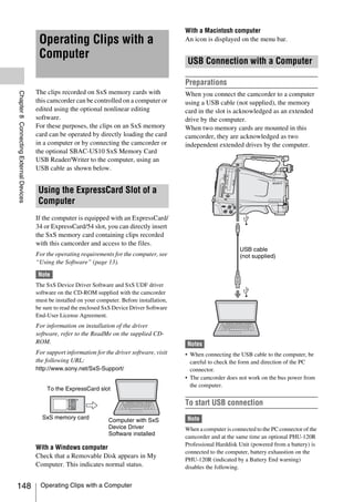
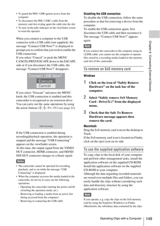
![may not be maintained. To avoid such a problem, use the
application software.
Connecting an External
For the operating requirements, see “Camcorder
system configuration” (page 12), and for installation Device (i.LINK
and operations, refer to the “XDCAM EX web sites”
(page 12) or User’s Guide contained in the CD- Connection)
ROM.
For support information on the application software,
Chapter 8 Connecting External Devices
You can record the same images as those
visit the web sites shown in “XDCAM EX web sites”
recorded on the memory card in this camcorder
(page 12) or the web sites shown in “Camcorder
on an external device connected to the i.LINK
system configuration” (page 12) or on the cover
(HDV/DV) connector, or record the playback
page of the supplied CD-ROM.
picture of the external device on the memory card
in the camcorder.
To use a nonlinear editing system When you connect the camcorder to a non-linear
For a nonlinear editing system, optional editing editing system that supports HDV format, you
software that corresponds to the recording can edit the images recorded on the memory card
formats used with this camcorder is required. in the camcorder.
Store the clips to be edited on the HDD of your
Notes
computer in advance, using the supplied
application software. • When you set OPERATION >Input/Output
Some editing software may not operate properly. >Output&i.LINK in the setup menu to [480P (570P)],
no signal is output from the HD/SD SDI OUT
Be sure to confirm before use that it conforms to
connector.
the recording formats used with this camcorder.
• Use the i.LINK (HDV/DV) connector only for one-to-
one i.LINK connection.
• When you change a setting which affects output
signals from the i.LINK (HDV/DV) connector, such as
HD/SD, HD System Line, System Frequency, and Rec
Format under OPERATION >Format in the setup
menu or i.LINK I/O and Down Converter under
OPERATION >Input/Output in the setup menu,
disconnect the i.LINK cable and change the setting.
Changing such a setting with the i.LINK cable
connected may cause improper operation of the
connected i.LINK device.
• The external signal input via the i.LINK connection
that can be recorded on the camcorder is HDV streams
only. You cannot record DV streams via the i.LINK
connection.
Recording the Camera Picture on
an External Device
The picture being shot with this camcorder is
output as an HDV or DV stream via the i.LINK
(HDV/DV) connector. It can be recorded on a
connected HDV or DVCAM recorder in
synchronization with a recording start/stop
operation on this camcorder.
1 Perform the preparatory settings of the
camcorder.
150 Connecting an External Device (i.LINK Connection)](https://image.slidesharecdn.com/pmw-320lenk-120216080013-phpapp02/85/Sony-PMW-320K-Operation-Manual-150-320.jpg)
![• Set OPERATION >Input/Output >Output
& i.LINK in the setup menu (see Nonlinear Editing
page 100) to “HD & HDV” or “SD &
HDV”. You can transfer an HDV stream to a nonlinear
HD & HDV or SD & HDV: To output an editing system connected via the i.LINK (HDV/
HDV stream in HD mode when the DV) connector.
video format is set to an HDV Notes
compatible format (SP 1440/59.94i,
Chapter 8 Connecting External Devices
• The i.LINK (HDV/DV) connector of this camcorder is
SP 1440/50i, or SP 1440/23.94P) a 6-pin connector. Check the number of pins of the
SD & DV: To output a DV stream i.LINK connector on your computer and use an
• Set OPERATION >Input/Output >i.LINK appropriate i.LINK cable.
I/O in the setup menu to [Enable]. • In searching pictures of this camcorder on the
• Set MAINTENANCE >Trigger Mode computer, it may take some time until the display is
>i.LINK Trigger Mode in the setup menu reflected on the computer.
(see page 129) to [Both] or [External]. • If the playback clip is short or the playback starting
Both: To perform recording both on the point is near the end of the clip, the i.LINK signal may
be interrupted between the clip and the next clip. When
memory card in this camcorder and on
you try to capture such a signal using the nonlinear
the external device
editing system, a malfunction may occur, depending
External: To perform recording only on on the nonlinear editing software in use.
the external device • If you specify a search speed other than 4, 15, or 24
times normal with the nonlinear editing system, no
2 Set the external device to recording i.LINK signal is fed out. In such a case, the picture on
standby status. the viewfinder monitor may stay frozen.
For operations of the external device, refer to • High-speed playback picture may not be displayed on
the operation manual of that device. the computer screen, depending on the nonlinear
editing software in use.
3 Start recording. Setting on this camcorder
The external device starts recording in Set OPERATION >Input/Output >i.LINK I/O in
synchronization. the setup menu to [Enable].
For operations of the nonlinear editing software,
The status of the external device is displayed in refer to the operation manual of the software.
the i.LINK status indication area (see page 31) on
the viewfinder screen.
Indication Status of the external device Recording External Input Signals
STBY HDV In HDV recording standby
The HDV stream input from a device connected
zREC HDV In HDV recording via the i.LINK (HDV/DV) connector can be
STBY DV In DV recording standby recorded on an SxS memory card in this
In DV recording camcorder.
zREC DV
The timecodes superimposed on the i.LINK input
are recorded regardless of the settings of the
Notes
camcorder.
• Operation may be different depending on the type of
external device. Note
• When you execute the operation to make a recording DV stream cannot be recorded.
on the recording media loaded in the camcorder while
HDV signals are output from the i.LINK (HDV/DV) 1 Set the external signal to a format that
connector, HDV signal output stops for about one can be recorded on the camcorder.
second before the recording starts, and then it resumes.
Select an HDV compatible format (SP 1440/
• While you can record shot marks on the memory card
59.94i, SP 1440/50i, or SP 1440/23.94P) for
during recording, they are not added to the pictures
recorded on the external device. the video format.
Connecting an External Device (i.LINK Connection) 151](https://image.slidesharecdn.com/pmw-320lenk-120216080013-phpapp02/85/Sony-PMW-320K-Operation-Manual-151-320.jpg)
![2 Make the following settings with
OPERATION >Input/Output in the Configuring a Shooting
setup menu (see page 100).
• Set Output&i.LINK to [HD&HDV] or and Recording System
[SD&HDV].
• Set i.LINK I/O to [Enable].
• Set Source Select to [i.LINK]. If you install the optional CBK-CE01 on this
The input video is displayed on the camcorder, you can attach the XDCA-55 HD
Chapter 8 Connecting External Devices
viewfinder screen or the monitor connected Camera Adaptor and connect the XDCU-50 HD
to the VIDEO OUT connector. Camera Extension Unit.
Audio signals are output through the built-in This allows you to configure a shooting and
speaker, the headphones connected to the recording system consisting of multiple
EARPHONE connector, and the speaker of camcorders with camera extension units
the monitor connected to the VIDEO OUT connected to a remote control unit. For more
connector. information about the XDCA-55 and XDCU-50,
refer to their respective operation manuals.
3 Start the recording. Note
Notes When using the camcorder in this system, do not connect
• An error is generated in the following cases. In such a a video light to the camcorder.
case, cancel Recording mode.
- The video format of input signal does not match that
specified on the camcorder.
- A copy-protected stream is being fed in.
• If the input to the camcorder becomes no signal during
recording, the TALLY indicators, the tally indicator on
the front of the viewfinder, and the REC indication
(zREC) on the viewfinder screen flash, indicating that
no signal is being recorded on the SxS memory card.
When an input signal is resumed, recording is
restarted, incrementing the clip number on the memory
card.
152 Configuring a Shooting and Recording System](https://image.slidesharecdn.com/pmw-320lenk-120216080013-phpapp02/85/Sony-PMW-320K-Operation-Manual-152-320.jpg)
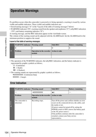
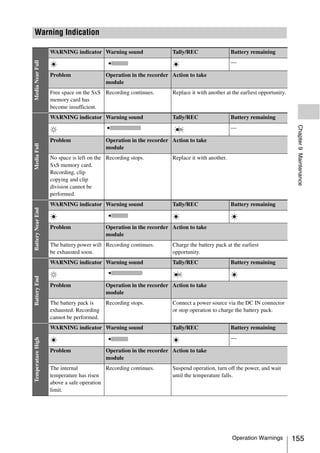
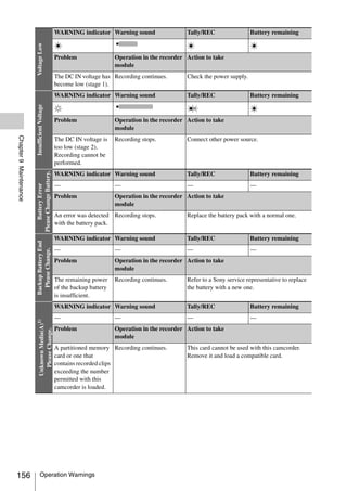
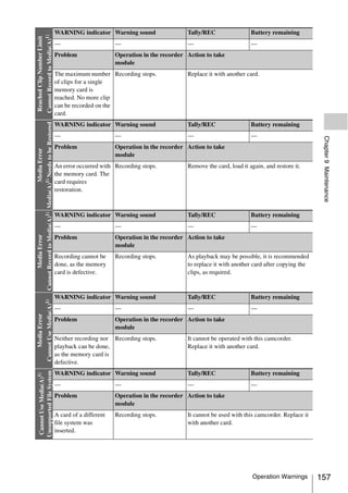
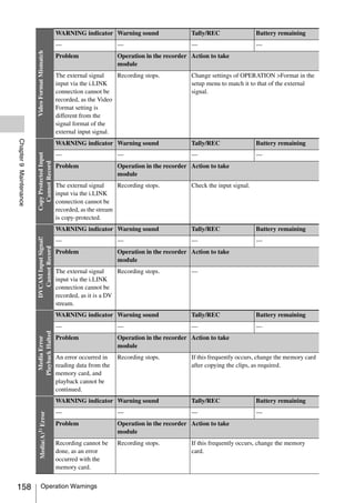
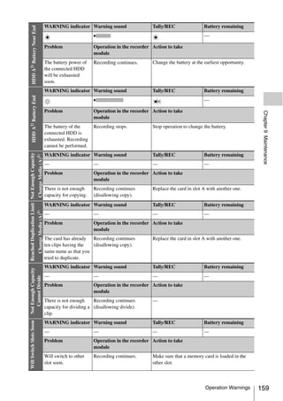
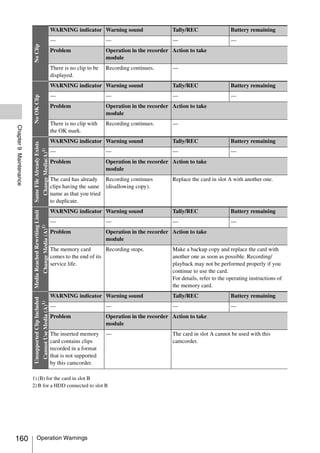
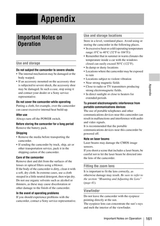
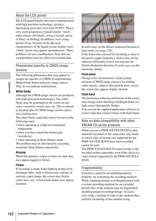
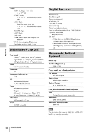
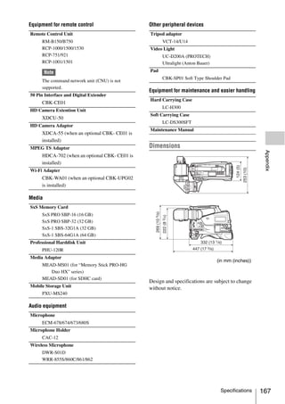
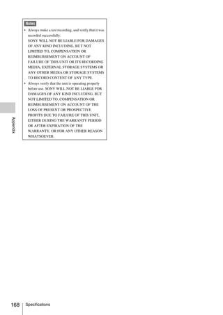
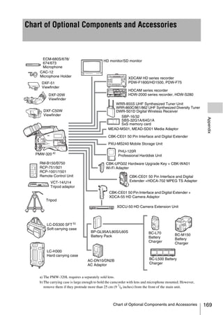
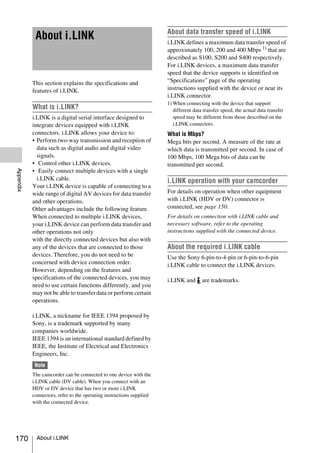
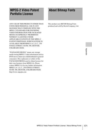
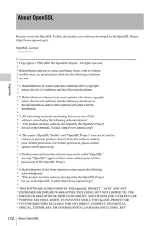
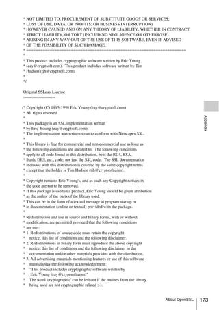
![* 4. If you include any Windows specific code (or a derivative thereof) from
* the apps directory (application code) you must include an acknowledgement:
* "This product includes software written by Tim Hudson (tjh@cryptsoft.com)"
*
* THIS SOFTWARE IS PROVIDED BY ERIC YOUNG ``AS IS'' AND
* ANY EXPRESS OR IMPLIED WARRANTIES, INCLUDING, BUT NOT LIMITED TO, THE
* IMPLIED WARRANTIES OF MERCHANTABILITY AND FITNESS FOR A PARTICULAR PURPOSE
* ARE DISCLAIMED. IN NO EVENT SHALL THE AUTHOR OR CONTRIBUTORS BE LIABLE
* FOR ANY DIRECT, INDIRECT, INCIDENTAL, SPECIAL, EXEMPLARY, OR CONSEQUENTIAL
* DAMAGES (INCLUDING, BUT NOT LIMITED TO, PROCUREMENT OF SUBSTITUTE GOODS
* OR SERVICES; LOSS OF USE, DATA, OR PROFITS; OR BUSINESS INTERRUPTION)
* HOWEVER CAUSED AND ON ANY THEORY OF LIABILITY, WHETHER IN CONTRACT, STRICT
* LIABILITY, OR TORT (INCLUDING NEGLIGENCE OR OTHERWISE) ARISING IN ANY WAY
* OUT OF THE USE OF THIS SOFTWARE, EVEN IF ADVISED OF THE POSSIBILITY OF
* SUCH DAMAGE.
*
* The licence and distribution terms for any publically available version or
* derivative of this code cannot be changed. i.e. this code cannot simply be
* copied and put under another distribution licence
Appendix
* [including the GNU Public Licence.]
*/
174 About OpenSSL](https://image.slidesharecdn.com/pmw-320lenk-120216080013-phpapp02/85/Sony-PMW-320K-Operation-Manual-174-320.jpg)


The PMW-320K/320L is a shoulder-mount HD memory camcorder that supports multi-format recording including 1080/59.94i, 1080/50i, 1080/29.97P, 1080/23.98P, 720/59.94P, 720/29.97P, 720/23.98P, 1080/25P, 720/50P, and 720/25P. It has three 1/2-type full-HD CMOS image sensors and a 1/2-type bayonet mount. The camcorder can also record and play back SD signals in DVCAM-AVI format and output HD signals down-converted to SD.