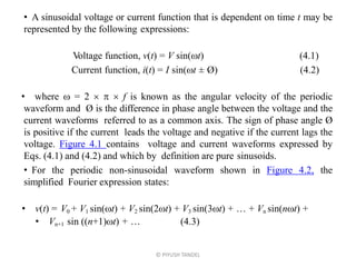
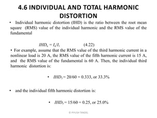
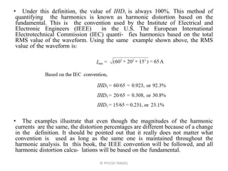
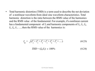
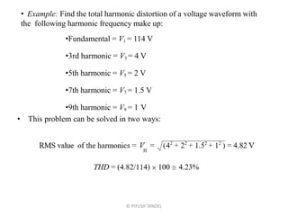
SlideShare a Scribd company logo
1 of 59
POWER QUALITY
Prof. Piyush N. Tandel
Electrical Engineering
MGITER, Navsari
Chapter . 4
Harmonics
© PIYUSH TANDEL
DEFINITION OF HARMONICS
• Webster’s New World Dictionary defines harmonics as pure tones making
up a composite tone in music. A pure tone is a musical sound of a single
frequency, and a combination of many pure tones makes up a composite
sound. Sound waves are electromagnetic waves traveling through space as a
periodic function of time. Can the principle behind pure music tones apply to
other functions or quantities that are time dependent? In the early 1800s,
French mathematician, Jean Baptiste Fourier formulated that a periodic non-
sinusoidal function of a fundamental frequency f may be expressed as the
sum of sinusoidal functions of frequencies which are multiples of the
fundamental frequency. In our discussions here, we are mainly concerned
with periodic functions of voltage and current due to their importance in the
field of power quality. In other applications, the periodic function might refer
to radio frequency transmission, heat flow through a medium, vibrations of a
mechanical structure, or the motions of a pendulum in a clock.
© PIYUSH TANDEL
• A sinusoidal voltage or current function that is dependent on time t may be
represented by the following expressions:
Voltage function, v(t) = V sin(t) (4.1)
Current function, i(t) = I sin(t ± Ø) (4.2)
• where  = 2    f is known as the angular velocity of the periodic
waveform and Ø is the difference in phase angle between the voltage and the
current waveforms referred to as a common axis. The sign of phase angle Ø
is positive if the current leads the voltage and negative if the current lags the
voltage. Figure 4.1 contains voltage and current waveforms expressed by
Eqs. (4.1) and (4.2) and which by definition are pure sinusoids.
• For the periodic non-sinusoidal waveform shown in Figure 4.2, the
simplified Fourier expression states:
• v(t) = V0 + V1 sin(t) + V2 sin(2t) + V3 sin(3t) + … + Vn sin(nt) +
• Vn+1 sin ((n+1)t) + … (4.3)
© PIYUSH TANDEL
© PIYUSH TANDEL
© PIYUSH TANDEL
• The Fourier expression is an infinite series. In this equation, V0 represents
the constant or the DC component of the waveform. V1, V2, V3, …, Vn are the
peak values of the successive terms of the expression. The terms are known
as the harmonics of the periodic waveform. The fundamental (or first
harmonic) frequency has a frequency of f, the second harmonic has a
frequency of 2  f, the third harmonic has a frequency of 3  f, and the nth
harmonic has a frequency of n  f. If the fundamental frequency is 60 Hz (as
in the U.S.), the second harmonic frequency is 120 Hz, and the third
harmonic frequency is 180 Hz.
• The significance of harmonic frequencies can be seen in Figure 4.3. The
second harmonic undergoes two complete cycles during one cycle of the
fundamental frequency, and the third harmonic traverses three complete cycles
during one cycle of the fundamental frequency. V1, V2, and V3 are the peak
values of the harmonic components that comprise the composite waveform,
which also has a frequency of f.
© PIYUSH TANDEL
© PIYUSH TANDEL
• The ability to express a nonsinusoidal waveform as a sum of sinusoidal waves
allows us to use the more common mathematical expressions and formulas to solve
power system problems. In order to find the effect of a nonsinusoidal voltage or
current on a piece of equipment, we only need to determine the effect of the
individual harmonics and then vectorially sum the results to derive the net effect.
Figure 4.4 illustrates how individual harmonics that are sinusoidal can be added to
form a nonsinusoidal wave- form.
• The Fourier expression in Eq. (4.3) has been simplified to clarify the concept
behind harmonic frequency components in a nonlinear periodic function. For the
purist, the following more precise expression is offered. For a periodic voltage
wave with fundamental frequency of  = 2f,
• where ak and bk are the coefficients of the individual harmonic terms or
components. Under certain conditions, the cosine or sine terms can vanish, giving
us a simpler expression. If the function is an even function, meaning f (–t) = f (t),
then the sine terms vanish from the expression. If the function is odd, with f (–t) =
–f (t), then the cosine terms disappear. For our analysis, we will use the simplified
expression involving sine terms only. It should be noted that having both sine and
cosine terms affects only the displacement angle of the harmonic components and
the shape of the nonlinear wave and does not alter the principle behind application
of the Fourier series.
© PIYUSH TANDEL
v (t) = V0 +  (ak cos kt + bk sin k t) (for k = 1 to )
• The coefficients of the harmonic terms of a function f (t) contained in Eq.
(4.4) are determined by:
• The coefficients represent the peak values of the individual harmonic
frequency terms of the nonlinear periodic function represented by f (t). It is
not the intent of this book to explore the intricacies of the Fourier series.
Several books in mathematics are available for the reader who wants to
develop a deeper understanding of this very essential tool for solving
power quality problems related to harmonics.
© PIYUSH TANDEL
HARMONIC NUMBER (h )
• Harmonic number (h) refers to the individual frequency elements that comprise
a composite waveform. For example, h = 5 refers to the fifth harmonic
component with a frequency equal to five times the fundamental frequency. If
the fundamental frequency is 60 Hz, then the fifth harmonic frequency is 5 
60, or 300 Hz. The harmonic number 6 is a component with a frequency of 360
Hz. Dealing with harmonic numbers and not with harmonic frequencies is
done for two reasons. The fundamental frequency varies among individual
countries and applications. The fundamental frequency in the U.S. is 60 Hz,
whereas in Europe and many Asian countries it is 50 Hz. Also, some
applications use frequencies other than 50 or 60 Hz; for example, 400 Hz is a
common frequency in the aerospace industry, while some AC systems for
electric traction use 25 Hz as the frequency. The inverter part of an AC
adjustable speed drive can operate at any frequency between zero and its full
rated maximum frequency, and the fundamental frequency then becomes the
frequency at which the motor is operating. The use of harmonic numbers allows
us to simplify how we express harmonics. The second reason for using
harmonic numbers is the simplification realized in performing mathematical
operations involving harmonics.
© PIYUSH TANDEL
3. ODD AND EVEN ORDER HARMONICS
• As their names imply, odd harmonics have odd numbers (e.g., 3, 5, 7, 9,
11), and even harmonics have even numbers (e.g., 2, 4, 6, 8, 10). Harmonic
number 1 is assigned to the fundamental frequency component of the periodic
wave. Harmonic number 0 represents the constant or DC component of the
waveform. The DC component is the net difference between the positive and
negative halves of one complete waveform cycle. Figure 4.5 shows a periodic
waveform with net DC content. The DC component of a waveform has
undesirable effects, particularly on transformers, due to the phenomenon of
core saturation. Saturation of the core is caused by operating the core at
magnetic field levels above the knee of the magnetization curve. Transformers
are designed to operate below the knee portion of the curve. When DC
voltages or currents are applied to the transformer winding, large DC
magnetic fields are set up in the transformer core. The sum of the AC and the
DC magnetic fields can shift the transformer operation into regions past the
knee of the saturation curve. Operation in the saturation region places large
excitation power requirements on the power system. The transformer losses
are substantially increased, causing excessive temperature rise. Core vibration
becomes more pronounced as a result of operation in the saturation region.
© PIYUSH TANDEL
© PIYUSH TANDEL
• We usually look at harmonics as integers, but some applications produce
harmonic voltages and currents that are not integers. Electric arc furnaces are
examples of loads that generate non-integer harmonics. Arc welders can also
generate non- integer harmonics. In both cases, once the arc stabilizes, the
non-integer harmonics mostly disappear, leaving only the integer harmonics.
• The majority of nonlinear loads produce harmonics that are odd multiples
of the fundamental frequency. Certain conditions need to exist for production
of even harmonics. Uneven current draw between the positive and negative
halves of one cycle of operation can generate even harmonics. The uneven
operation may be due to the nature of the application or could indicate
problems with the load circuitry. Transformer magnetizing currents contain
appreciable levels of even harmonic components and so do arc furnaces during
startup.
• Subharmonics have frequencies below the fundamental frequency and are
rare in power systems. When subharmonics are present, the underlying cause is
resonance between the harmonic currents or voltages with the power system
capacitance and inductance. Subharmonics may be generated when a system is
highly inductive (such as an arc furnace during startup) or if the power system
also contains large capacitor banks for power factor correction or filtering.
Such conditions produce slow oscillations that are relatively undamped,
resulting in voltage sags and light flicker.
© PIYUSH TANDEL
4.4 HARMONIC PHASE ROTATION AND PHASE
ANGLE RELATIONSHIP
• So far we have treated harmonics as stand-alone entities working to produce
wave- form distortion in AC voltages and currents. This approach is valid if we
are looking at single-phase voltages or currents; however, in a three-phase
power system, the harmonics of one phase have a rotational and phase angle
relationship with the harmonics of the other phases. In power system studies
involving harmonics, this relationship is important.
• In a balanced three-phase electrical system, the voltages and currents have a
positional relationship as shown in Figure 4.6. The three voltages are 120˚ apart
and so are the three currents. The normal phase rotation or sequence is a–b–c,
which is counterclockwise and designated as the positive-phase sequence in this
book. For harmonic analyses, these relationships are still applicable, but the
fundamental components of voltages and currents are used as reference. All other
harmonics use the fundamental frequency as the reference. The fundamental
frequencies have a positive-phase sequence. The angle between the fundamental
voltage and the fundamental current is the displacement power factor angle.
© PIYUSH TANDEL
© PIYUSH TANDEL
• So how do the harmonics fit into this space–time picture? For a clearer
understanding, let us look only at the current harmonic phasors. We can
further simplify the picture by limiting the discussion to odd harmonics
only, which under normal and balanced conditions are the most prevalent.
The following relationships are true for the fundamental frequency
current components in a three-phase power system:
• The negative displacement angles indicate that the fundamental phasors ib1
and ic1 trail the ia1 phasor by the indicated angle. Figure 4.7a shows the
fundamental current phasors.
© PIYUSH TANDEL
• The expressions for the third harmonic currents are:
• The expressions for the third harmonics show that they are in phase and
have zero displacement angle between them. Figure 4.7b shows the third
harmonic phasors. The third harmonic currents are known as zero
sequence harmonics due to the zero displacement angle between the three
phasors.
© PIYUSH TANDEL
© PIYUSH TANDEL
• The expressions for the fifth harmonic currents are:
• Figure 4.7d shows the seventh harmonic current phasors. The seventh
harmonics have the same phase sequence as the fundamental and are
positive sequence harmonics. So far, we have not included even harmonics
in the discussion; doing so is left to the reader as an exercise. Table 4.1
categorizes the harmonics in terms of their respective sequence orders.
© PIYUSH TANDEL
• The expressions shown so far for harmonics have zero phase shifts with
respect to the fundamental. It is not uncommon for the harmonics to have a
phase-angle shift with respect to the fundamental. Figure 4.8 depicts a fifth
harmonic current waveform with and without phase shift from the
fundamental. Expressions for the fifth harmonics with a phase-shift angle
of  degrees are:
• While the phase-shift angle has the effect of altering the shape of the
composite waveform, the phase sequence order of the harmonics is not
affected.
© PIYUSH TANDEL
© PIYUSH TANDEL
4.5 CAUSES OF VOLTAGE AND CURRENT
HARMONICS
• A pure sinusoidal waveform with zero harmonic distortion is a hypothetical
quantity and not a practical one. The voltage waveform, even at the point of
generation, contains a small amount of distortion due to non-uniformity in the
excitation magnetic field and discrete spatial distribution of coils around the
generator stator slots. The distortion at the point of generation is usually very
low, typically less than 1.0%. The generated voltage is transmitted many
hundreds of miles, transformed to several levels, and ultimately distributed to
the power user. The user equipment generates currents that are rich in
harmonic frequency components, especially in large commercial or industrial
installations. As harmonic currents travel to the power source, the current
distortion results in additional voltage distortion due to impedance volt- ages
associated with the various power distribution equipment, such as transmission
and distribution lines, transformers, cables, buses, and so on. Figure 4.9
illustrates how current distortion is transformed into voltage distortion. Not all
voltage distortion, however, is due to the flow of distorted current through the
power system impedance.
© PIYUSH TANDEL
© PIYUSH TANDEL
• For instance, static uninterruptible power source (UPS) systems can
generate appreciable voltage distortion due to the nature of their operation.
Normal AC voltage is converted to DC and then reconverted to AC in the
inverter section of the UPS. Unless waveform shaping circuitry is provided,
the voltage waveforms generated in UPS units tend to be distorted.
• As nonlinear loads are propagated into the power system, voltage
distortions are introduced which become greater moving from the source to
the load because of the circuit impedances. Current distortions for the most
part are caused by loads. Even loads that are linear will generate nonlinear
currents if the supply voltage waveform is significantly distorted. When
several power users share a common power line, the voltage distortion
produced by harmonic current injection of one user can affect the other users.
This is why standards are being issued that will limit the amount of harmonic
currents that individual power users can feed into the source (an issue that we
will examine later in this chapter). The major causes of current distortion are
nonlinear loads due to adjustable speed drives, fluorescent lighting, rectifier
banks, computer and data-processing loads, arc furnaces, and so on. One can
easily visualize an environment where a wide spectrum of harmonic
frequencies are generated and transmitted to other loads or other power users,
thereby producing undesirable results throughout the system.
© PIYUSH TANDEL
4.6 INDIVIDUAL AND TOTAL HARMONIC
DISTORTION
• Individual harmonic distortion (IHD) is the ratio between the root mean
square (RMS) value of the individual harmonic and the RMS value of the
fundamental
IHDn = In/I1 (4.22)
• For example, assume that the RMS value of the third harmonic current in a
nonlinear load is 20 A, the RMS value of the fifth harmonic current is 15 A,
and the RMS value of the fundamental is 60 A. Then, the individual third
harmonic distortion is:
• IHD3 = 20/60 = 0.333, or 33.3%
• and the individual fifth harmonic distortion is:
• IHD5 = 15/60 = 0.25, or 25.0%
© PIYUSH TANDEL
• Under this definition, the value of IHD1 is always 100%. This method of
quantifying the harmonics is known as harmonic distortion based on the
fundamental. This is the convention used by the Institute of Electrical and
Electronic Engineers (IEEE) in the U.S. The European International
Electrotechnical Commission (IEC) quanti- fies harmonics based on the total
RMS value of the waveform. Using the same example shown above, the RMS
value of the waveform is:
• The examples illustrate that even though the magnitudes of the harmonic
currents are the same, the distortion percentages are different because of a change
in the definition. It should be pointed out that it really does not matter what
convention is used as long as the same one is maintained throughout the
harmonic analysis. In this book, the IEEE convention will be followed, and all
harmonic distortion calcu- lations will be based on the fundamental.
© PIYUSH TANDEL
• Total harmonic distortion (THD) is a term used to describe the net deviation
of a nonlinear waveform from ideal sine waveform characteristics. Total
harmonic distortion is the ratio between the RMS value of the harmonics
and the RMS value of the fundamental. For example, if a nonlinear current
has a fundamental component of I1 and harmonic components of I2, I3, I4,
I5, I6, I7, …, then the RMS value of the harmonics is:
© PIYUSH TANDEL
© PIYUSH TANDEL
• Example: Find the total harmonic distortion of a voltage waveform with
the following harmonic frequency make up:
•Fundamental = V1 = 114 V
•3rd harmonic = V3 = 4 V
•5th harmonic = V5 = 2 V
•7th harmonic = V7 = 1.5 V
•9th harmonic = V9 = 1 V
• This problem can be solved in two ways:
• or find the individual harmonic distortions:
• IHD3 = 4/114 = 3.51%
• IHD5 = 2/114 = 1.75%
• IHD7 = 1.5/114 = 1.32%
• IHD9 = 1/114 = 0.88%
• By definition, IHD1 = 100%, so
• The results are not altered by using either the magnitude of the RMS quantities or
the individual harmonic distortion values.
• The individual harmonic distortion indicates the contribution of each harmonic
frequency to the distorted waveform, and the total harmonic distortion describes the
net deviation due to all the harmonics. These are both important parameters. In order
to solve harmonic problems, we require information on the composition of the
individual distortions so that any treatment may be tailored to suit the problem. The
total harmonic distortion, while conveying no information on the harmonic makeup,
is used to describe the degree of pollution of the power system as far as harmonics
are concerned. Defining the individual and total harmonic distortions will be helpful
as we look at some typical nonlinear waveforms and their harmonic frequency
characteristics.
© PIYUSH TANDEL
HARMONIC SIGNATURES
• Many of the loads installed in present-day power systems are harmonic
current generators. Combined with the impedance of the electrical system,
the loads also produce harmonic voltages. The nonlinear loads may
therefore be viewed as both harmonic current generators and harmonic
voltage generators. Prior to the 1970s, speed control of AC motors was
primarily achieved using belts and pulleys. Now, adjustable speed drives
(ASDs) perform speed control functions very efficiently. ASDs are
generators of large harmonic currents. Fluorescent lights use less electrical
energy for the same light output as incandescent lighting but produce
substantial harmonic currents in the process. The explosion of personal
computer use has resulted in harmonic current proliferation in commercial
buildings. This section is devoted to describing, in no particular order, a
few of the more common nonlinear loads that surround us in our everyday
life.
© PIYUSH TANDEL
1. FLUORESCENT LIGHTING
• Figure 4.10 shows a current waveform at a distribution panel supplying
exclusively fluorescent lights. The waveform is primarily comprised of the
third and the fifth harmonic frequencies. The individual current harmonic
distortion makeup is pro- vided in Table 4.2. The waveform also contains
slight traces of even harmonics, especially of the higher frequency order. The
current waveform is flat topped due to initiation of arc within the gas tube,
which causes the voltage across the tube and the current to become essentially
unchanged for a portion of each half of a cycle.
© PIYUSH TANDEL
© PIYUSH TANDEL
2. ADJUSTABLE SPEED DRIVES
• While several technologies exist for creating a variable voltage and variable
frequency power source for the speed control of AC motors, the pulse-width
modulation (PWM) drive technology is currently the most widely used.
Figures 4.11 and 4.12 show current graphs at the ASD input lines with a
motor operating at 60 and 45 Hz, respectively. The characteristic double hump
for each half cycle of the AC waveform is due to conduction of the input
rectifier modules for a duration of two 60˚ periods for each half cycle. As the
operating frequency is reduced, the humps become pronounced with a large
increase in the total harmonic distortion. The THD of 74.2% for 45-Hz
operation is excessive and can produce many deletrious effects, as will be
shown in later sections of this chapter.
• Figure 4.13 is the waveform of the voltage at the ASD input power lines. It
was stated earlier that large current distortions can produce significant voltage
distortions. In this particular case, the voltage THD is 8.3%, which is higher
than levels typically found in most industrial installations. High levels of
voltage THD also produce unwanted results
• Figure 4.14 is the current waveform of an ASD of smaller horsepower. This
drive contains line side inductors which, along with the higher inductance of
the motor, produce a current waveform with less distortion.
© PIYUSH TANDEL
© PIYUSH TANDEL
© PIYUSH TANDEL
© PIYUSH TANDEL
FIGURE 4.13 Adjustable speed drive input voltage with motor operating at 60 Hz.
© PIYUSH TANDEL
3 PERSONAL COMPUTER AND MONITOR
• Figures 4.15 and 4.16 show the nonlinear current characteristics of a
personal computer and a computer monitor, respectively. The current THD for
both devices exceeds 100%, as the result of high levels of individual
distortions introduced by the third and fifth harmonics. The total current
drawn by a personal computer and its monitor is less than 2 A, but a typical
high-rise building can contain several hundred computers and monitors. The
net effect of this on the total current harmonic distortion of a facility is not
difficult to visualize.
• So far we have examined some of the more common harmonic current
generators. The examples illustrate that a wide spectrum of harmonic currents
is generated. Depending on the size of the power source and the harmonic
current makeup, the composite harmonic picture will be different from
facility to facility.
© PIYUSH TANDEL
© PIYUSH TANDEL
EFFECT OF HARMONICS ON
POWER SYSTEM DEVICES
• We are interested in the subject of harmonics because of the harmful effects
they have on power system devices. What makes harmonics so insidious is
that very often the effects of harmonics are not known until failure occurs.
Insight into how harmonics can interact within a power system and how
they can affect power system components is important for preventing
failures. In this section, we will look at the effect of harmonics on some
common power system devices.
© PIYUSH TANDEL
TRANSFORMERS
• Harmonics can affect transformers primarily in two ways. Voltage
harmonics pro- duce additional losses in the transformer core as the higher
frequency harmonic voltages set up hysteresis loops, which superimpose
on the fundamental loop. Each loop represents higher magnetization power
requirements and higher core losses. A second and a more serious effect of
harmonics is due to harmonic frequency currents in the transformer
windings. The harmonic currents increase the net RMS current flowing in
the transformer windings which results in additional I2R losses. Winding
eddy current losses are also increased. Winding eddy currents are circulating
currents induced in the conductors by the leakage magnetic flux. Eddy
current concentrations are higher at the ends of the windings due to the
crowding effect of the leakage magnetic field at the coil extremities. The
winding eddy current losses increase as the square of the harmonic current
and the square of the frequency of the current.
© PIYUSH TANDEL
• Thus, the eddy loss (EC) is proportional to I 2  h2, where I is the RMS
value of the harmonic current of order h, and h is the harmonic frequency
order or number. Eddy currents due to harmonics can significantly increase
the transformer winding temperature. Transformers that are required to
supply large nonlinear loads must be derated to handle the harmonics. This
derating factor is based on the percentage of the harmonic currents in the
load and the rated winding eddy current losses.
• One method by which transformers may be rated for suitability to handle
harmonic loads is by k factor ratings. The k factor is equal to the sum of the
square of the harmonic frequency currents (expressed as a ratio of the total
RMS current) multiplied by the square of the harmonic frequency numbers:
k = I 2
12
+ I 2
22
+ I 2
32
+ I 2
42
+  + I 2
n2
(4.25)• 1 2 3 4 n
• where
I1 is the ratio between the fundamental current and the total RMS current.
I2 is the ratio between the second harmonic current and the total RMS current.
I3 is the ratio between the third harmonic current and the total RMS current.
© PIYUSH TANDEL
2. AC MOTORS
• Application of distorted voltage to a motor results in additional losses in the
magnetic core of the motor. Hysteresis and eddy current losses in the core
increase as higher frequency harmonic voltages are impressed on the motor
windings. Hysteresis losses increase with frequency and eddy current losses
increase as the square of the frequency. Also, harmonic currents produce
additional I2R losses in the motor windings which must be accounted for.
• Another effect, and perhaps a more serious one, is torsional oscillations due to
harmonics. Table 4.1 classified harmonics into one of three categories. Two of the
more prominent harmonics found in a typical power system are the fifth and
seventh harmonics. The fifth harmonic is a negative sequence harmonic, and the
resulting magnetic field revolves in a direction opposite to that of the
fundamental field at a speed five times the fundamental. The seventh harmonic is
a positive sequence harmonic with a resulting magnetic field revolving in the
same direction as the fundamental field at a speed seven times the fundamental.
The net effect is a magnetic field that revolves at a relative speed of six times the
speed of the rotor. This induces currents in the rotor bars at a frequency of six
times the fundamental frequency. The resulting interaction between the magnetic
fields and the rotor-induced currents produces torsional oscillations of the motor
shaft. If the frequency of the oscillation coincides with the natural frequency of
the motor rotating members, severe damage to the motor can result. Excessive
vibration and noise in a motor operating in a harmonic environment should be
investigated to prevent failures.
© PIYUSH TANDEL
3 CAPACITOR BANKS
• Capacitor banks are commonly found in commercial and industrial power
systems to correct for low power factor conditions. Capacitor banks are
designed to operate at a maximum voltage of 110% of their rated voltages and
at 135% of their rated kVARS. When large levels of voltage and current
harmonics are present, the ratings are quite often exceeded, resulting in
failures. Because the reactance of a capacitor bank is inversely proportional to
frequency, harmonic currents can find their way into a capacitor bank. The
capacitor bank acts as a sink, absorbing stray harmonic currents and causing
overloads and subsequent failure of the bank.
• A more serious condition with potential for substantial damage occurs due to a
phenomenon called harmonic resonance. Resonance conditions are created
when the inductive and capacitive reactances become equal at one of the
harmonic frequencies. The two types of resonances are series and parallel. In
general, series resonance produces voltage amplification and parallel resonance
results in current multiplication. Resonance will not be analyzed in this book,
but many textbooks on electrical circuit theory are available that can be
consulted for further explanation. In a harmonic-rich environment, both series
and parallel resonance may be present. If a high level of harmonic voltage or
current corresponding to the resonance frequency exists in a power system,
considerable damage to the capacitor bank as well as other power system
devices can result. The following example might help to illustrate power
system resonance due to capacitor banks.
© PIYUSH TANDEL
CABLES
• Current flowing in a cable produces I2R losses. When the load current contains
harmonic content, additional losses are introduced. To compound the problem,
the effective resistance of the cable increases with frequency because of the
phenomenon known as skin effect. Skin effect is due to unequal flux linkage
across the cross section of the conductor which causes AC currents to flow only
on the outer periphery of the conductor. This has the effect of increasing the
resistance of the conductor for AC currents. The higher the frequency of the
current, the greater the tendency of the current to crowd at the outer periphery of
the conductor and the greater the effective resistance for that frequency.
• The capacity of a cable to carry nonlinear loads may be determined as follows.
The skin effect factor is calculated first. The skin effect factor depends on the
skin depth, which is an indicator of the penetration of the current in a conductor.
Skin depth () is inversely proportional to the square root of the frequency:
 = S f
• where S is a proportionality constant based on the physical characteristics of
the cable and its magnetic permeability and f is the frequency of the current.
© PIYUSH TANDEL
5. BUSWAYS
• Most commercial multistory installations contain busways that serve as the
primary source of electrical power to various floors. Busways that
incorporate sandwiched bus-bars are susceptible to nonlinear loading,
especially if the neutral bus carries large levels of triplen harmonic currents
(third, ninth, etc.). Under the worst possible conditions, the neutral bus
may be forced to carry a current equal to 173% of the phase currents. In
cases where substantial neutral currents are expected, the busways must be
suitably derated.
© PIYUSH TANDEL
PROTECTIVE DEVICES
• Harmonic currents influence the operation of protective devices. Fuses and
motor thermal overload devices are prone to nuisance operation when
subjected to nonlinear currents. This factor should be given due
consideration when sizing protective devices for use in a harmonic
environment. Electromechanical relays are also affected by harmonics.
Depending on the design, an electromechanical relay may operate faster or
slower than the expected times for operation at the fundamental frequency
alone. Such factors should be carefully considered prior to placing the
relays in service.
© PIYUSH TANDEL
GUIDELINES FOR HARMONIC VOLTAGE AND
CURRENT LIMITATION
• So far we have discussed the adverse effects of harmonics on power system operation. It
is important, therefore, that attempts be made to limit the harmonic distortion that a facility
might produce. There are two reasons for this. First, the lower the harmonic currents
produced in an electrical system, the better the equipment within the confinement of the
system will perform. Also, lower harmonic currents produce less of an impact on other
power users sharing the same power lines of the harmonic generating power system. The
IEEE 519 standard provides guidelines for harmonic current limits at the point of common
coupling (PCC) between the facility and the utility. The rationale behind the use of the PCC
as the reference location is simple. It is a given fact that within a particular power use
environment, harmonic currents will be generated and propagated. Harmonic current
injection at the PCC determines how one facility might affect other power users and the
utility that supplies the power. Table 4.11 (per IEEE 519) lists harmonic current limits based
on the size of the power user. As the ratio between the maximum available short circuit
current at the PCC and the maximum demand load current increases, the percentage of the
harmonic currents that are allowed also increases. This means that larger power users are
allowed to inject into the system only a minimal amount of harmonic current (as a
percentage of the fundamental current). Such a scheme tends to equalize the amounts of
harmonic currents that large and small users of power are allowed to inject into the power
system at the PCC.
© PIYUSH TANDEL
• IEEE 519 also provides guidelines for maximum voltage distortion at the
PCC (see Table 4.12). Limiting the voltage distortion at the PCC is the
concern of the utility. It can be expected that as long as a facility’s harmonic
current contribution is within the IEEE 519 limits the voltage distortion at the
PCC will also be within the specified limits.
• When the IEEE 519 harmonic limits are used as guidelines within a facility,
the PCC is the common junction between the harmonic generating loads
and other electrical equipment in the power system. It is expected that
applying IEEE guide- lines renders power system operation more reliable.
In the future, more and more utilities might require facilities to limit their
harmonic current injection to levels stipulated by IEEE 519. The following
section contains information on how har- monic mitigation might be
achieved.
© PIYUSH TANDEL
© PIYUSH TANDEL
HARMONIC CURRENT MITIGATION
• The use of electronic power devices is steadily increasing. It is estimated that
more than 70% of the loading of a facility by year 2010 will be due to nonlinear
loads, thus demand is increasing for product manufacturers to produce devices that
generate lower distortion. The importance of equipment design in minimizing
harmonic current production has taken on greater importance, as reflected by
technological improvements in fluorescent lamp ballasts, adjustable speed drives,
battery chargers, and uninterruptible power source (UPS) units. Computers and
similar data-process- ing devices contain switching mode power supplies that
generate a substantial amount of harmonic currents, as seen earlier. Designing
power supplies for electronic equipment adds considerably to the cost of the units
and can also make the equipment heavier. At this time, when computer prices are
extremely competitive, attempts to engineer power supplies that draw low
harmonic currents are not a priority.
• Adjustable speed drive (ASD) technology is evolving steadily, with greater
emphasis being placed on a reduction in harmonic currents. Older generation
ASDs using current source inverter (CSI) and voltage source inverter (VSI)
technologies produced considerable harmonic frequency currents. The significant
harmonic fre- quency currents generated in power conversion equipment can be
stated as:
© PIYUSH TANDEL
1. EQUIPMENT DESIGN
n = kq ± 1
• where n is the significant harmonic frequency, k is any positive integer (1, 2, 3,
etc.), and q is the pulse number of the power conversion equipment which is the
number of power pulses that are in one complete sequence of power conversion.
For example, a three-phase full wave bridge rectifier has six power pulses and
therefore has a pulse number of 6. With six-pulse-power conversion equipment,
the following significant harmonics may be generated:
For k =1, n = (1  6) ± 1 = 5th and 7th harmonics. For k =2, n = (2
 6) ± 1 = 11th and 13th harmonics.
• With six-pulse-power conversion equipment, harmonics below the 5th
harmonic are insignificant. Also, as the harmonic number increases, the
individual harmonic distortions become lower due to increasing impedance
presented to higher frequency components by the power system inductive
reactance. So, typically, for six-pulse- power conversion equipment, the 5th
harmonic current would be the highest, the 7th would be lower than the 5th, the
11th would be lower than the 7th, and so on, as shown below:
I13 < I11< I7< I5
• We can deduce that, when using 12-pulse-power conversion equipment,
harmonics below the 11th harmonic can be made insignificant. The total harmonic
distortion is also considerably reduced. Twelve-pulse-power conversion
equipment costs more than six-pulse-power equipment. Where harmonic currents
are the primary concern, 24-pulse-power conversion equipment may be
considered. © PIYUSH TANDEL
2. HARMONIC CURRENT CANCELLATION
• Transformer connections employing phase shift are sometimes used to effect
cancellation of harmonic currents in a power system. Triplen harmonic (3rd, 9th,
15th, etc.) currents are a set of currents that can be effectively trapped using a
special transformer configuration called the zigzag connection. In power
systems, triplen harmonics add in the neutral circuit, as these currents are in
phase. Using a zigzag connection, the triplens can be effectively kept away from
the source. Figure 4.20 illustrates how this is accomplished.
• The transformer phase-shifting principle is also used to achieve cancellation of
the 5th and the 7th harmonic currents. Using a – and a –Y transformer to
supply harmonic producing loads in parallel as shown in Figure 4.21, the 5th and
the 7th harmonics are canceled at the point of common connection. This is due to
the 30˚ phase shift between the two transformer connections. As the result of this,
the source does not see any significant amount of the 5th and 7th harmonics. If
the nonlinear loads supplied by the two transformers are identical, then
maximum harmonic current cancellation takes place; otherwise, some 5th and
7th harmonic currents would still be present. Other phase-shifting methods may
be used to cancel higher harmonics if they are found to be a problem. Some
transformer manufacturers offer multiple phase-shifting connections in a single
package which saves cost and space compared to using individual transformers.
© PIYUSH TANDEL
© PIYUSH TANDEL
© PIYUSH TANDEL
3.HARMONIC FILTERS
• Nonlinear loads produce harmonic currents that can travel to other locations in
the power system and eventually back to the source. As we saw earlier, harmonic
currents can produce a variety of effects that are harmful to the power system.
Harmonic currents are a result of the characteristics of particular loads. As long as
we choose to employ those loads, we must deal with the reality that harmonic
currents will exist to a degree dependent upon the loads. One means of ensuring
that harmonic currents produced by a nonlinear current source will not unduly
interfere with the rest of the power system is to filter out the harmonics.
Application of harmonic filters helps to accomplish this.
• Harmonic filters are broadly classified into passive and active filters. Passive
filters, as the name implies, use passive components such as resistors, inductors,
and capacitors. A combination of passive components is tuned to the harmonic
frequency that is to be filtered. Figure 4.22 is a typical series-tuned filter. Here the
values of the inductor and the capacitor are chosen to present a low impedance to
the harmonic frequency that is to be filtered out. Due to the lower impedance of
the filter in comparison to the impedance of the source, the harmonic frequency
current will circulate between the load and the filter. This keeps the harmonic
current of the desired frequency away from the source and other loads in the
power system. If other harmonic frequencies are to be filtered out, additional
tuned filters are applied in parallel. Applications such as arc furnaces require
multiple harmonic filters, as they generate large quantities of harmonic currents at
several frequencies.
© PIYUSH TANDEL
• Applying harmonic filters requires careful consideration. Series-tuned filters appear
to be of low impedance to harmonic currents but they also form a parallel
resonance circuit with the source impedance. In some instances, a situation can be
created that is worse than the condition being corrected. It is imperative that
computer simulations of the entire power system be performed prior to applying
harmonic filters. As a first step in the computer simulation, the power system is
modeled to indicate the locations of the harmonic sources, then hypothetical
harmonic filters are placed in the model and the response of the power system to the
filter is examined. If unacceptable results are obtained, the location and values of
the filter parameters are changed until the results are satisfactory. When applying
harmonic filters, the units are almost never tuned to the exact harmonic frequency.
For example, the 5th harmonic frequency may be designed for resonance at the
4.7th harmonic frequency.
© PIYUSH TANDEL
• By not creating a resonance circuit at precisely the 5th harmonic frequency,
we can minimize the possibility of the filter resonating with other loads or the
source, thus forming a parallel resonance circuit at the 5th harmonic. The
4.7th harmonic filter would still be effective in filtering out the 5th harmonic
currents. This is evident from the series-tuned frequency vs. impedance curve
shown in Figure 4.22.
• Sometimes, tuned filters are configured to provide power factor correction
for a facility as well as harmonic current filtering. In such cases the filter
would be designed to carry the resonant harmonic frequency current and also
the normal frequency current at the fundamental frequency. In either case, a
power system harmonic study is paramount to ensure that no ill effects would
be produced by the application of the power factor correction/filter circuit.
© PIYUSH TANDEL
End of Chapter 4
© PIYUSH TANDEL

More Related Content

What's hot

Identification and minimization of Harmonics
Identification and minimization of HarmonicsIdentification and minimization of Harmonics
Identification and minimization of HarmonicsMayur Hiwale
 
harmonic distortion ppt
harmonic distortion pptharmonic distortion ppt
harmonic distortion pptAditi Tiwari
 
Harmonics in power system
Harmonics in power systemHarmonics in power system
Harmonics in power systemMinh Anh Nguyen
 
Harmonic presentation 11 6-2018
Harmonic presentation 11 6-2018Harmonic presentation 11 6-2018
Harmonic presentation 11 6-2018WN4UUY
 
POWER HARMONICS- SOURCES, ISSUES AND MITIGATION
POWER HARMONICS- SOURCES, ISSUES AND MITIGATIONPOWER HARMONICS- SOURCES, ISSUES AND MITIGATION
POWER HARMONICS- SOURCES, ISSUES AND MITIGATIONASHIKS842
 
Harmonics Effects in Power System
Harmonics Effects in Power SystemHarmonics Effects in Power System
Harmonics Effects in Power SystemIJERA Editor
 
Harmonics and mitigation techniques
Harmonics and mitigation techniquesHarmonics and mitigation techniques
Harmonics and mitigation techniquesrifat maryum
 
Transformer Harmonics
Transformer HarmonicsTransformer Harmonics
Transformer HarmonicsAcme Electric
 
Harmonic mitigating transformer
Harmonic mitigating transformerHarmonic mitigating transformer
Harmonic mitigating transformerBiswajit Pratihari
 
Analysis of harmonic at different level on distribution system ,its effect a...
Analysis of harmonic at different level on distribution system ,its effect  a...Analysis of harmonic at different level on distribution system ,its effect  a...
Analysis of harmonic at different level on distribution system ,its effect a...Anuj Arora
 
Harmonics mitigation solutions
Harmonics mitigation solutionsHarmonics mitigation solutions
Harmonics mitigation solutionsFahad Shaikh
 

What's hot (20)

Identification and minimization of Harmonics
Identification and minimization of HarmonicsIdentification and minimization of Harmonics
Identification and minimization of Harmonics
 
harmonic distortion ppt
harmonic distortion pptharmonic distortion ppt
harmonic distortion ppt
 
Harmonic reduction
Harmonic reductionHarmonic reduction
Harmonic reduction
 
Harmonics
HarmonicsHarmonics
Harmonics
 
Harmonics in power system
Harmonics in power systemHarmonics in power system
Harmonics in power system
 
Harmonic presentation 11 6-2018
Harmonic presentation 11 6-2018Harmonic presentation 11 6-2018
Harmonic presentation 11 6-2018
 
Mill harmonics r1
Mill harmonics r1Mill harmonics r1
Mill harmonics r1
 
Hormonics impact and_mitigation
Hormonics impact and_mitigationHormonics impact and_mitigation
Hormonics impact and_mitigation
 
Vivek harmonics
Vivek harmonicsVivek harmonics
Vivek harmonics
 
POWER HARMONICS- SOURCES, ISSUES AND MITIGATION
POWER HARMONICS- SOURCES, ISSUES AND MITIGATIONPOWER HARMONICS- SOURCES, ISSUES AND MITIGATION
POWER HARMONICS- SOURCES, ISSUES AND MITIGATION
 
MAJOE PROJECT PPT
MAJOE PROJECT PPTMAJOE PROJECT PPT
MAJOE PROJECT PPT
 
Harmonics Effects in Power System
Harmonics Effects in Power SystemHarmonics Effects in Power System
Harmonics Effects in Power System
 
Ps harmonics
Ps harmonicsPs harmonics
Ps harmonics
 
Harmonics and mitigation techniques
Harmonics and mitigation techniquesHarmonics and mitigation techniques
Harmonics and mitigation techniques
 
Transformer Harmonics
Transformer HarmonicsTransformer Harmonics
Transformer Harmonics
 
Harmonic mitigating transformer
Harmonic mitigating transformerHarmonic mitigating transformer
Harmonic mitigating transformer
 
Harmonics
HarmonicsHarmonics
Harmonics
 
Harmonics
HarmonicsHarmonics
Harmonics
 
Analysis of harmonic at different level on distribution system ,its effect a...
Analysis of harmonic at different level on distribution system ,its effect  a...Analysis of harmonic at different level on distribution system ,its effect  a...
Analysis of harmonic at different level on distribution system ,its effect a...
 
Harmonics mitigation solutions
Harmonics mitigation solutionsHarmonics mitigation solutions
Harmonics mitigation solutions
 

Similar to Chep 04 Harmonics

Are Harmonics Still a Problem in Data Centers ?
Are Harmonics Still a Problem in Data Centers ?Are Harmonics Still a Problem in Data Centers ?
Are Harmonics Still a Problem in Data Centers ?Edarat Group
 
Single phase AC circuit
Single phase AC  circuit  Single phase AC  circuit
Single phase AC circuit MuhammadAli2362
 
Ac circuits notes
Ac circuits   notesAc circuits   notes
Ac circuits notesmadhu1729
 
International Journal of Computational Engineering Research(IJCER)
International Journal of Computational Engineering Research(IJCER)International Journal of Computational Engineering Research(IJCER)
International Journal of Computational Engineering Research(IJCER)ijceronline
 
3.Frequency Domain Representation of Signals and Systems
3.Frequency Domain Representation of Signals and Systems3.Frequency Domain Representation of Signals and Systems
3.Frequency Domain Representation of Signals and SystemsINDIAN NAVY
 
02 Cap 1 - power-system-harmonics-2015.pdf
02 Cap 1 - power-system-harmonics-2015.pdf02 Cap 1 - power-system-harmonics-2015.pdf
02 Cap 1 - power-system-harmonics-2015.pdfROCIOMAMANIALATA1
 
Ece320 notes-part1
Ece320 notes-part1Ece320 notes-part1
Ece320 notes-part1Memo Love
 
1400383104 lecture 1 to 4 word file
1400383104 lecture 1 to 4 word file1400383104 lecture 1 to 4 word file
1400383104 lecture 1 to 4 word fileDeepthi Shibuz
 
Ac waveform and ac circuit theory of sinusoids
Ac waveform and ac circuit theory of sinusoidsAc waveform and ac circuit theory of sinusoids
Ac waveform and ac circuit theory of sinusoidsSoham Gajjar
 
Page 1 of 4 FARADAY’S LAW Introduction I.docx
Page 1 of 4 FARADAY’S LAW  Introduction  I.docxPage 1 of 4 FARADAY’S LAW  Introduction  I.docx
Page 1 of 4 FARADAY’S LAW Introduction I.docxalfred4lewis58146
 
International Refereed Journal of Engineering and Science (IRJES)
International Refereed Journal of Engineering and Science (IRJES)International Refereed Journal of Engineering and Science (IRJES)
International Refereed Journal of Engineering and Science (IRJES)irjes
 
1.1 Generation of alternating voltage, phasor representation of sinusoidal qu...
1.1 Generation of alternating voltage, phasor representation of sinusoidal qu...1.1 Generation of alternating voltage, phasor representation of sinusoidal qu...
1.1 Generation of alternating voltage, phasor representation of sinusoidal qu...KrishnaKorankar
 
38_286_Study_on_Mitigation_of_Harmonics_by_Using_Passive_Filter_and_Active_Fi...
38_286_Study_on_Mitigation_of_Harmonics_by_Using_Passive_Filter_and_Active_Fi...38_286_Study_on_Mitigation_of_Harmonics_by_Using_Passive_Filter_and_Active_Fi...
38_286_Study_on_Mitigation_of_Harmonics_by_Using_Passive_Filter_and_Active_Fi...ssuser5b27192
 

Similar to Chep 04 Harmonics (20)

Are Harmonics Still a Problem in Data Centers ?
Are Harmonics Still a Problem in Data Centers ?Are Harmonics Still a Problem in Data Centers ?
Are Harmonics Still a Problem in Data Centers ?
 
Single phase AC circuit
Single phase AC  circuit  Single phase AC  circuit
Single phase AC circuit
 
Ac circuits notes
Ac circuits   notesAc circuits   notes
Ac circuits notes
 
International Journal of Computational Engineering Research(IJCER)
International Journal of Computational Engineering Research(IJCER)International Journal of Computational Engineering Research(IJCER)
International Journal of Computational Engineering Research(IJCER)
 
3.Frequency Domain Representation of Signals and Systems
3.Frequency Domain Representation of Signals and Systems3.Frequency Domain Representation of Signals and Systems
3.Frequency Domain Representation of Signals and Systems
 
ECE131 Unit 1 lecture 9.pptx
ECE131 Unit 1 lecture 9.pptxECE131 Unit 1 lecture 9.pptx
ECE131 Unit 1 lecture 9.pptx
 
signal.ppt
signal.pptsignal.ppt
signal.ppt
 
02 Cap 1 - power-system-harmonics-2015.pdf
02 Cap 1 - power-system-harmonics-2015.pdf02 Cap 1 - power-system-harmonics-2015.pdf
02 Cap 1 - power-system-harmonics-2015.pdf
 
Ece320 notes-part1
Ece320 notes-part1Ece320 notes-part1
Ece320 notes-part1
 
electrical machines
electrical machineselectrical machines
electrical machines
 
1400383104 lecture 1 to 4 word file
1400383104 lecture 1 to 4 word file1400383104 lecture 1 to 4 word file
1400383104 lecture 1 to 4 word file
 
Ac waveform and ac circuit theory of sinusoids
Ac waveform and ac circuit theory of sinusoidsAc waveform and ac circuit theory of sinusoids
Ac waveform and ac circuit theory of sinusoids
 
Ece320 notes-part1
Ece320 notes-part1Ece320 notes-part1
Ece320 notes-part1
 
Ece320 notes-part1 2
Ece320 notes-part1 2Ece320 notes-part1 2
Ece320 notes-part1 2
 
Page 1 of 4 FARADAY’S LAW Introduction I.docx
Page 1 of 4 FARADAY’S LAW  Introduction  I.docxPage 1 of 4 FARADAY’S LAW  Introduction  I.docx
Page 1 of 4 FARADAY’S LAW Introduction I.docx
 
International Refereed Journal of Engineering and Science (IRJES)
International Refereed Journal of Engineering and Science (IRJES)International Refereed Journal of Engineering and Science (IRJES)
International Refereed Journal of Engineering and Science (IRJES)
 
1.1 Generation of alternating voltage, phasor representation of sinusoidal qu...
1.1 Generation of alternating voltage, phasor representation of sinusoidal qu...1.1 Generation of alternating voltage, phasor representation of sinusoidal qu...
1.1 Generation of alternating voltage, phasor representation of sinusoidal qu...
 
What is Harmonics ?
What is Harmonics ?What is Harmonics ?
What is Harmonics ?
 
38_286_Study_on_Mitigation_of_Harmonics_by_Using_Passive_Filter_and_Active_Fi...
38_286_Study_on_Mitigation_of_Harmonics_by_Using_Passive_Filter_and_Active_Fi...38_286_Study_on_Mitigation_of_Harmonics_by_Using_Passive_Filter_and_Active_Fi...
38_286_Study_on_Mitigation_of_Harmonics_by_Using_Passive_Filter_and_Active_Fi...
 
Inverter 2003
Inverter 2003Inverter 2003
Inverter 2003
 

Recently uploaded

ONLINE FOOD ORDER SYSTEM PROJECT REPORT.pdf
ONLINE FOOD ORDER SYSTEM PROJECT REPORT.pdfONLINE FOOD ORDER SYSTEM PROJECT REPORT.pdf
ONLINE FOOD ORDER SYSTEM PROJECT REPORT.pdfKamal Acharya
 
College Call Girls Nashik Nehal 7001305949 Independent Escort Service Nashik
College Call Girls Nashik Nehal 7001305949 Independent Escort Service NashikCollege Call Girls Nashik Nehal 7001305949 Independent Escort Service Nashik
College Call Girls Nashik Nehal 7001305949 Independent Escort Service NashikCall Girls in Nagpur High Profile
 
Call Girls Service Nashik Vaishnavi 7001305949 Independent Escort Service Nashik
Call Girls Service Nashik Vaishnavi 7001305949 Independent Escort Service NashikCall Girls Service Nashik Vaishnavi 7001305949 Independent Escort Service Nashik
Call Girls Service Nashik Vaishnavi 7001305949 Independent Escort Service NashikCall Girls in Nagpur High Profile
 
Structural Analysis and Design of Foundations: A Comprehensive Handbook for S...
Structural Analysis and Design of Foundations: A Comprehensive Handbook for S...Structural Analysis and Design of Foundations: A Comprehensive Handbook for S...
Structural Analysis and Design of Foundations: A Comprehensive Handbook for S...Dr.Costas Sachpazis
 
Call Girls in Nagpur Suman Call 7001035870 Meet With Nagpur Escorts
Call Girls in Nagpur Suman Call 7001035870 Meet With Nagpur EscortsCall Girls in Nagpur Suman Call 7001035870 Meet With Nagpur Escorts
Call Girls in Nagpur Suman Call 7001035870 Meet With Nagpur EscortsCall Girls in Nagpur High Profile
 
AKTU Computer Networks notes --- Unit 3.pdf
AKTU Computer Networks notes ---  Unit 3.pdfAKTU Computer Networks notes ---  Unit 3.pdf
AKTU Computer Networks notes --- Unit 3.pdfankushspencer015
 
KubeKraft presentation @CloudNativeHooghly
KubeKraft presentation @CloudNativeHooghlyKubeKraft presentation @CloudNativeHooghly
KubeKraft presentation @CloudNativeHooghlysanyuktamishra911
 
MANUFACTURING PROCESS-II UNIT-2 LATHE MACHINE
MANUFACTURING PROCESS-II UNIT-2 LATHE MACHINEMANUFACTURING PROCESS-II UNIT-2 LATHE MACHINE
MANUFACTURING PROCESS-II UNIT-2 LATHE MACHINESIVASHANKAR N
 
(PRIYA) Rajgurunagar Call Girls Just Call 7001035870 [ Cash on Delivery ] Pun...
(PRIYA) Rajgurunagar Call Girls Just Call 7001035870 [ Cash on Delivery ] Pun...(PRIYA) Rajgurunagar Call Girls Just Call 7001035870 [ Cash on Delivery ] Pun...
(PRIYA) Rajgurunagar Call Girls Just Call 7001035870 [ Cash on Delivery ] Pun...ranjana rawat
 
Russian Call Girls in Nagpur Grishma Call 7001035870 Meet With Nagpur Escorts
Russian Call Girls in Nagpur Grishma Call 7001035870 Meet With Nagpur EscortsRussian Call Girls in Nagpur Grishma Call 7001035870 Meet With Nagpur Escorts
Russian Call Girls in Nagpur Grishma Call 7001035870 Meet With Nagpur EscortsCall Girls in Nagpur High Profile
 
CCS335 _ Neural Networks and Deep Learning Laboratory_Lab Complete Record
CCS335 _ Neural Networks and Deep Learning Laboratory_Lab Complete RecordCCS335 _ Neural Networks and Deep Learning Laboratory_Lab Complete Record
CCS335 _ Neural Networks and Deep Learning Laboratory_Lab Complete RecordAsst.prof M.Gokilavani
 
Booking open Available Pune Call Girls Koregaon Park 6297143586 Call Hot Ind...
Booking open Available Pune Call Girls Koregaon Park  6297143586 Call Hot Ind...Booking open Available Pune Call Girls Koregaon Park  6297143586 Call Hot Ind...
Booking open Available Pune Call Girls Koregaon Park 6297143586 Call Hot Ind...Call Girls in Nagpur High Profile
 
BSides Seattle 2024 - Stopping Ethan Hunt From Taking Your Data.pptx
BSides Seattle 2024 - Stopping Ethan Hunt From Taking Your Data.pptxBSides Seattle 2024 - Stopping Ethan Hunt From Taking Your Data.pptx
BSides Seattle 2024 - Stopping Ethan Hunt From Taking Your Data.pptxfenichawla
 
Extrusion Processes and Their Limitations
Extrusion Processes and Their LimitationsExtrusion Processes and Their Limitations
Extrusion Processes and Their Limitations120cr0395
 
High Profile Call Girls Nagpur Isha Call 7001035870 Meet With Nagpur Escorts
High Profile Call Girls Nagpur Isha Call 7001035870 Meet With Nagpur EscortsHigh Profile Call Girls Nagpur Isha Call 7001035870 Meet With Nagpur Escorts
High Profile Call Girls Nagpur Isha Call 7001035870 Meet With Nagpur Escortsranjana rawat
 
Top Rated Pune Call Girls Budhwar Peth ⟟ 6297143586 ⟟ Call Me For Genuine Se...
Top Rated  Pune Call Girls Budhwar Peth ⟟ 6297143586 ⟟ Call Me For Genuine Se...Top Rated  Pune Call Girls Budhwar Peth ⟟ 6297143586 ⟟ Call Me For Genuine Se...
Top Rated Pune Call Girls Budhwar Peth ⟟ 6297143586 ⟟ Call Me For Genuine Se...Call Girls in Nagpur High Profile
 
UNIT - IV - Air Compressors and its Performance
UNIT - IV - Air Compressors and its PerformanceUNIT - IV - Air Compressors and its Performance
UNIT - IV - Air Compressors and its Performancesivaprakash250
 

Recently uploaded (20)

ONLINE FOOD ORDER SYSTEM PROJECT REPORT.pdf
ONLINE FOOD ORDER SYSTEM PROJECT REPORT.pdfONLINE FOOD ORDER SYSTEM PROJECT REPORT.pdf
ONLINE FOOD ORDER SYSTEM PROJECT REPORT.pdf
 
College Call Girls Nashik Nehal 7001305949 Independent Escort Service Nashik
College Call Girls Nashik Nehal 7001305949 Independent Escort Service NashikCollege Call Girls Nashik Nehal 7001305949 Independent Escort Service Nashik
College Call Girls Nashik Nehal 7001305949 Independent Escort Service Nashik
 
Call Girls Service Nashik Vaishnavi 7001305949 Independent Escort Service Nashik
Call Girls Service Nashik Vaishnavi 7001305949 Independent Escort Service NashikCall Girls Service Nashik Vaishnavi 7001305949 Independent Escort Service Nashik
Call Girls Service Nashik Vaishnavi 7001305949 Independent Escort Service Nashik
 
Structural Analysis and Design of Foundations: A Comprehensive Handbook for S...
Structural Analysis and Design of Foundations: A Comprehensive Handbook for S...Structural Analysis and Design of Foundations: A Comprehensive Handbook for S...
Structural Analysis and Design of Foundations: A Comprehensive Handbook for S...
 
DJARUM4D - SLOT GACOR ONLINE | SLOT DEMO ONLINE
DJARUM4D - SLOT GACOR ONLINE | SLOT DEMO ONLINEDJARUM4D - SLOT GACOR ONLINE | SLOT DEMO ONLINE
DJARUM4D - SLOT GACOR ONLINE | SLOT DEMO ONLINE
 
Call Girls in Nagpur Suman Call 7001035870 Meet With Nagpur Escorts
Call Girls in Nagpur Suman Call 7001035870 Meet With Nagpur EscortsCall Girls in Nagpur Suman Call 7001035870 Meet With Nagpur Escorts
Call Girls in Nagpur Suman Call 7001035870 Meet With Nagpur Escorts
 
(INDIRA) Call Girl Aurangabad Call Now 8617697112 Aurangabad Escorts 24x7
(INDIRA) Call Girl Aurangabad Call Now 8617697112 Aurangabad Escorts 24x7(INDIRA) Call Girl Aurangabad Call Now 8617697112 Aurangabad Escorts 24x7
(INDIRA) Call Girl Aurangabad Call Now 8617697112 Aurangabad Escorts 24x7
 
AKTU Computer Networks notes --- Unit 3.pdf
AKTU Computer Networks notes ---  Unit 3.pdfAKTU Computer Networks notes ---  Unit 3.pdf
AKTU Computer Networks notes --- Unit 3.pdf
 
KubeKraft presentation @CloudNativeHooghly
KubeKraft presentation @CloudNativeHooghlyKubeKraft presentation @CloudNativeHooghly
KubeKraft presentation @CloudNativeHooghly
 
MANUFACTURING PROCESS-II UNIT-2 LATHE MACHINE
MANUFACTURING PROCESS-II UNIT-2 LATHE MACHINEMANUFACTURING PROCESS-II UNIT-2 LATHE MACHINE
MANUFACTURING PROCESS-II UNIT-2 LATHE MACHINE
 
(PRIYA) Rajgurunagar Call Girls Just Call 7001035870 [ Cash on Delivery ] Pun...
(PRIYA) Rajgurunagar Call Girls Just Call 7001035870 [ Cash on Delivery ] Pun...(PRIYA) Rajgurunagar Call Girls Just Call 7001035870 [ Cash on Delivery ] Pun...
(PRIYA) Rajgurunagar Call Girls Just Call 7001035870 [ Cash on Delivery ] Pun...
 
Russian Call Girls in Nagpur Grishma Call 7001035870 Meet With Nagpur Escorts
Russian Call Girls in Nagpur Grishma Call 7001035870 Meet With Nagpur EscortsRussian Call Girls in Nagpur Grishma Call 7001035870 Meet With Nagpur Escorts
Russian Call Girls in Nagpur Grishma Call 7001035870 Meet With Nagpur Escorts
 
CCS335 _ Neural Networks and Deep Learning Laboratory_Lab Complete Record
CCS335 _ Neural Networks and Deep Learning Laboratory_Lab Complete RecordCCS335 _ Neural Networks and Deep Learning Laboratory_Lab Complete Record
CCS335 _ Neural Networks and Deep Learning Laboratory_Lab Complete Record
 
Water Industry Process Automation & Control Monthly - April 2024
Water Industry Process Automation & Control Monthly - April 2024Water Industry Process Automation & Control Monthly - April 2024
Water Industry Process Automation & Control Monthly - April 2024
 
Booking open Available Pune Call Girls Koregaon Park 6297143586 Call Hot Ind...
Booking open Available Pune Call Girls Koregaon Park  6297143586 Call Hot Ind...Booking open Available Pune Call Girls Koregaon Park  6297143586 Call Hot Ind...
Booking open Available Pune Call Girls Koregaon Park 6297143586 Call Hot Ind...
 
BSides Seattle 2024 - Stopping Ethan Hunt From Taking Your Data.pptx
BSides Seattle 2024 - Stopping Ethan Hunt From Taking Your Data.pptxBSides Seattle 2024 - Stopping Ethan Hunt From Taking Your Data.pptx
BSides Seattle 2024 - Stopping Ethan Hunt From Taking Your Data.pptx
 
Extrusion Processes and Their Limitations
Extrusion Processes and Their LimitationsExtrusion Processes and Their Limitations
Extrusion Processes and Their Limitations
 
High Profile Call Girls Nagpur Isha Call 7001035870 Meet With Nagpur Escorts
High Profile Call Girls Nagpur Isha Call 7001035870 Meet With Nagpur EscortsHigh Profile Call Girls Nagpur Isha Call 7001035870 Meet With Nagpur Escorts
High Profile Call Girls Nagpur Isha Call 7001035870 Meet With Nagpur Escorts
 
Top Rated Pune Call Girls Budhwar Peth ⟟ 6297143586 ⟟ Call Me For Genuine Se...
Top Rated  Pune Call Girls Budhwar Peth ⟟ 6297143586 ⟟ Call Me For Genuine Se...Top Rated  Pune Call Girls Budhwar Peth ⟟ 6297143586 ⟟ Call Me For Genuine Se...
Top Rated Pune Call Girls Budhwar Peth ⟟ 6297143586 ⟟ Call Me For Genuine Se...
 
UNIT - IV - Air Compressors and its Performance
UNIT - IV - Air Compressors and its PerformanceUNIT - IV - Air Compressors and its Performance
UNIT - IV - Air Compressors and its Performance
 

Chep 04 Harmonics

  • 1. POWER QUALITY Prof. Piyush N. Tandel Electrical Engineering MGITER, Navsari Chapter . 4 Harmonics © PIYUSH TANDEL
  • 2. DEFINITION OF HARMONICS • Webster’s New World Dictionary defines harmonics as pure tones making up a composite tone in music. A pure tone is a musical sound of a single frequency, and a combination of many pure tones makes up a composite sound. Sound waves are electromagnetic waves traveling through space as a periodic function of time. Can the principle behind pure music tones apply to other functions or quantities that are time dependent? In the early 1800s, French mathematician, Jean Baptiste Fourier formulated that a periodic non- sinusoidal function of a fundamental frequency f may be expressed as the sum of sinusoidal functions of frequencies which are multiples of the fundamental frequency. In our discussions here, we are mainly concerned with periodic functions of voltage and current due to their importance in the field of power quality. In other applications, the periodic function might refer to radio frequency transmission, heat flow through a medium, vibrations of a mechanical structure, or the motions of a pendulum in a clock. © PIYUSH TANDEL
  • 3. • A sinusoidal voltage or current function that is dependent on time t may be represented by the following expressions: Voltage function, v(t) = V sin(t) (4.1) Current function, i(t) = I sin(t ± Ø) (4.2) • where  = 2    f is known as the angular velocity of the periodic waveform and Ø is the difference in phase angle between the voltage and the current waveforms referred to as a common axis. The sign of phase angle Ø is positive if the current leads the voltage and negative if the current lags the voltage. Figure 4.1 contains voltage and current waveforms expressed by Eqs. (4.1) and (4.2) and which by definition are pure sinusoids. • For the periodic non-sinusoidal waveform shown in Figure 4.2, the simplified Fourier expression states: • v(t) = V0 + V1 sin(t) + V2 sin(2t) + V3 sin(3t) + … + Vn sin(nt) + • Vn+1 sin ((n+1)t) + … (4.3) © PIYUSH TANDEL
  • 6. • The Fourier expression is an infinite series. In this equation, V0 represents the constant or the DC component of the waveform. V1, V2, V3, …, Vn are the peak values of the successive terms of the expression. The terms are known as the harmonics of the periodic waveform. The fundamental (or first harmonic) frequency has a frequency of f, the second harmonic has a frequency of 2  f, the third harmonic has a frequency of 3  f, and the nth harmonic has a frequency of n  f. If the fundamental frequency is 60 Hz (as in the U.S.), the second harmonic frequency is 120 Hz, and the third harmonic frequency is 180 Hz. • The significance of harmonic frequencies can be seen in Figure 4.3. The second harmonic undergoes two complete cycles during one cycle of the fundamental frequency, and the third harmonic traverses three complete cycles during one cycle of the fundamental frequency. V1, V2, and V3 are the peak values of the harmonic components that comprise the composite waveform, which also has a frequency of f. © PIYUSH TANDEL
  • 8. • The ability to express a nonsinusoidal waveform as a sum of sinusoidal waves allows us to use the more common mathematical expressions and formulas to solve power system problems. In order to find the effect of a nonsinusoidal voltage or current on a piece of equipment, we only need to determine the effect of the individual harmonics and then vectorially sum the results to derive the net effect. Figure 4.4 illustrates how individual harmonics that are sinusoidal can be added to form a nonsinusoidal wave- form. • The Fourier expression in Eq. (4.3) has been simplified to clarify the concept behind harmonic frequency components in a nonlinear periodic function. For the purist, the following more precise expression is offered. For a periodic voltage wave with fundamental frequency of  = 2f, • where ak and bk are the coefficients of the individual harmonic terms or components. Under certain conditions, the cosine or sine terms can vanish, giving us a simpler expression. If the function is an even function, meaning f (–t) = f (t), then the sine terms vanish from the expression. If the function is odd, with f (–t) = –f (t), then the cosine terms disappear. For our analysis, we will use the simplified expression involving sine terms only. It should be noted that having both sine and cosine terms affects only the displacement angle of the harmonic components and the shape of the nonlinear wave and does not alter the principle behind application of the Fourier series. © PIYUSH TANDEL v (t) = V0 +  (ak cos kt + bk sin k t) (for k = 1 to )
  • 9. • The coefficients of the harmonic terms of a function f (t) contained in Eq. (4.4) are determined by: • The coefficients represent the peak values of the individual harmonic frequency terms of the nonlinear periodic function represented by f (t). It is not the intent of this book to explore the intricacies of the Fourier series. Several books in mathematics are available for the reader who wants to develop a deeper understanding of this very essential tool for solving power quality problems related to harmonics. © PIYUSH TANDEL
  • 10. HARMONIC NUMBER (h ) • Harmonic number (h) refers to the individual frequency elements that comprise a composite waveform. For example, h = 5 refers to the fifth harmonic component with a frequency equal to five times the fundamental frequency. If the fundamental frequency is 60 Hz, then the fifth harmonic frequency is 5  60, or 300 Hz. The harmonic number 6 is a component with a frequency of 360 Hz. Dealing with harmonic numbers and not with harmonic frequencies is done for two reasons. The fundamental frequency varies among individual countries and applications. The fundamental frequency in the U.S. is 60 Hz, whereas in Europe and many Asian countries it is 50 Hz. Also, some applications use frequencies other than 50 or 60 Hz; for example, 400 Hz is a common frequency in the aerospace industry, while some AC systems for electric traction use 25 Hz as the frequency. The inverter part of an AC adjustable speed drive can operate at any frequency between zero and its full rated maximum frequency, and the fundamental frequency then becomes the frequency at which the motor is operating. The use of harmonic numbers allows us to simplify how we express harmonics. The second reason for using harmonic numbers is the simplification realized in performing mathematical operations involving harmonics. © PIYUSH TANDEL
  • 11. 3. ODD AND EVEN ORDER HARMONICS • As their names imply, odd harmonics have odd numbers (e.g., 3, 5, 7, 9, 11), and even harmonics have even numbers (e.g., 2, 4, 6, 8, 10). Harmonic number 1 is assigned to the fundamental frequency component of the periodic wave. Harmonic number 0 represents the constant or DC component of the waveform. The DC component is the net difference between the positive and negative halves of one complete waveform cycle. Figure 4.5 shows a periodic waveform with net DC content. The DC component of a waveform has undesirable effects, particularly on transformers, due to the phenomenon of core saturation. Saturation of the core is caused by operating the core at magnetic field levels above the knee of the magnetization curve. Transformers are designed to operate below the knee portion of the curve. When DC voltages or currents are applied to the transformer winding, large DC magnetic fields are set up in the transformer core. The sum of the AC and the DC magnetic fields can shift the transformer operation into regions past the knee of the saturation curve. Operation in the saturation region places large excitation power requirements on the power system. The transformer losses are substantially increased, causing excessive temperature rise. Core vibration becomes more pronounced as a result of operation in the saturation region. © PIYUSH TANDEL
  • 13. • We usually look at harmonics as integers, but some applications produce harmonic voltages and currents that are not integers. Electric arc furnaces are examples of loads that generate non-integer harmonics. Arc welders can also generate non- integer harmonics. In both cases, once the arc stabilizes, the non-integer harmonics mostly disappear, leaving only the integer harmonics. • The majority of nonlinear loads produce harmonics that are odd multiples of the fundamental frequency. Certain conditions need to exist for production of even harmonics. Uneven current draw between the positive and negative halves of one cycle of operation can generate even harmonics. The uneven operation may be due to the nature of the application or could indicate problems with the load circuitry. Transformer magnetizing currents contain appreciable levels of even harmonic components and so do arc furnaces during startup. • Subharmonics have frequencies below the fundamental frequency and are rare in power systems. When subharmonics are present, the underlying cause is resonance between the harmonic currents or voltages with the power system capacitance and inductance. Subharmonics may be generated when a system is highly inductive (such as an arc furnace during startup) or if the power system also contains large capacitor banks for power factor correction or filtering. Such conditions produce slow oscillations that are relatively undamped, resulting in voltage sags and light flicker. © PIYUSH TANDEL
  • 14. 4.4 HARMONIC PHASE ROTATION AND PHASE ANGLE RELATIONSHIP • So far we have treated harmonics as stand-alone entities working to produce wave- form distortion in AC voltages and currents. This approach is valid if we are looking at single-phase voltages or currents; however, in a three-phase power system, the harmonics of one phase have a rotational and phase angle relationship with the harmonics of the other phases. In power system studies involving harmonics, this relationship is important. • In a balanced three-phase electrical system, the voltages and currents have a positional relationship as shown in Figure 4.6. The three voltages are 120˚ apart and so are the three currents. The normal phase rotation or sequence is a–b–c, which is counterclockwise and designated as the positive-phase sequence in this book. For harmonic analyses, these relationships are still applicable, but the fundamental components of voltages and currents are used as reference. All other harmonics use the fundamental frequency as the reference. The fundamental frequencies have a positive-phase sequence. The angle between the fundamental voltage and the fundamental current is the displacement power factor angle. © PIYUSH TANDEL
  • 16. • So how do the harmonics fit into this space–time picture? For a clearer understanding, let us look only at the current harmonic phasors. We can further simplify the picture by limiting the discussion to odd harmonics only, which under normal and balanced conditions are the most prevalent. The following relationships are true for the fundamental frequency current components in a three-phase power system: • The negative displacement angles indicate that the fundamental phasors ib1 and ic1 trail the ia1 phasor by the indicated angle. Figure 4.7a shows the fundamental current phasors. © PIYUSH TANDEL
  • 17. • The expressions for the third harmonic currents are: • The expressions for the third harmonics show that they are in phase and have zero displacement angle between them. Figure 4.7b shows the third harmonic phasors. The third harmonic currents are known as zero sequence harmonics due to the zero displacement angle between the three phasors. © PIYUSH TANDEL
  • 19. • The expressions for the fifth harmonic currents are: • Figure 4.7d shows the seventh harmonic current phasors. The seventh harmonics have the same phase sequence as the fundamental and are positive sequence harmonics. So far, we have not included even harmonics in the discussion; doing so is left to the reader as an exercise. Table 4.1 categorizes the harmonics in terms of their respective sequence orders. © PIYUSH TANDEL
  • 20. • The expressions shown so far for harmonics have zero phase shifts with respect to the fundamental. It is not uncommon for the harmonics to have a phase-angle shift with respect to the fundamental. Figure 4.8 depicts a fifth harmonic current waveform with and without phase shift from the fundamental. Expressions for the fifth harmonics with a phase-shift angle of  degrees are: • While the phase-shift angle has the effect of altering the shape of the composite waveform, the phase sequence order of the harmonics is not affected. © PIYUSH TANDEL
  • 22. 4.5 CAUSES OF VOLTAGE AND CURRENT HARMONICS • A pure sinusoidal waveform with zero harmonic distortion is a hypothetical quantity and not a practical one. The voltage waveform, even at the point of generation, contains a small amount of distortion due to non-uniformity in the excitation magnetic field and discrete spatial distribution of coils around the generator stator slots. The distortion at the point of generation is usually very low, typically less than 1.0%. The generated voltage is transmitted many hundreds of miles, transformed to several levels, and ultimately distributed to the power user. The user equipment generates currents that are rich in harmonic frequency components, especially in large commercial or industrial installations. As harmonic currents travel to the power source, the current distortion results in additional voltage distortion due to impedance volt- ages associated with the various power distribution equipment, such as transmission and distribution lines, transformers, cables, buses, and so on. Figure 4.9 illustrates how current distortion is transformed into voltage distortion. Not all voltage distortion, however, is due to the flow of distorted current through the power system impedance. © PIYUSH TANDEL
  • 24. • For instance, static uninterruptible power source (UPS) systems can generate appreciable voltage distortion due to the nature of their operation. Normal AC voltage is converted to DC and then reconverted to AC in the inverter section of the UPS. Unless waveform shaping circuitry is provided, the voltage waveforms generated in UPS units tend to be distorted. • As nonlinear loads are propagated into the power system, voltage distortions are introduced which become greater moving from the source to the load because of the circuit impedances. Current distortions for the most part are caused by loads. Even loads that are linear will generate nonlinear currents if the supply voltage waveform is significantly distorted. When several power users share a common power line, the voltage distortion produced by harmonic current injection of one user can affect the other users. This is why standards are being issued that will limit the amount of harmonic currents that individual power users can feed into the source (an issue that we will examine later in this chapter). The major causes of current distortion are nonlinear loads due to adjustable speed drives, fluorescent lighting, rectifier banks, computer and data-processing loads, arc furnaces, and so on. One can easily visualize an environment where a wide spectrum of harmonic frequencies are generated and transmitted to other loads or other power users, thereby producing undesirable results throughout the system. © PIYUSH TANDEL
  • 25. 4.6 INDIVIDUAL AND TOTAL HARMONIC DISTORTION • Individual harmonic distortion (IHD) is the ratio between the root mean square (RMS) value of the individual harmonic and the RMS value of the fundamental IHDn = In/I1 (4.22) • For example, assume that the RMS value of the third harmonic current in a nonlinear load is 20 A, the RMS value of the fifth harmonic current is 15 A, and the RMS value of the fundamental is 60 A. Then, the individual third harmonic distortion is: • IHD3 = 20/60 = 0.333, or 33.3% • and the individual fifth harmonic distortion is: • IHD5 = 15/60 = 0.25, or 25.0% © PIYUSH TANDEL
  • 26. • Under this definition, the value of IHD1 is always 100%. This method of quantifying the harmonics is known as harmonic distortion based on the fundamental. This is the convention used by the Institute of Electrical and Electronic Engineers (IEEE) in the U.S. The European International Electrotechnical Commission (IEC) quanti- fies harmonics based on the total RMS value of the waveform. Using the same example shown above, the RMS value of the waveform is: • The examples illustrate that even though the magnitudes of the harmonic currents are the same, the distortion percentages are different because of a change in the definition. It should be pointed out that it really does not matter what convention is used as long as the same one is maintained throughout the harmonic analysis. In this book, the IEEE convention will be followed, and all harmonic distortion calcu- lations will be based on the fundamental. © PIYUSH TANDEL
  • 27. • Total harmonic distortion (THD) is a term used to describe the net deviation of a nonlinear waveform from ideal sine waveform characteristics. Total harmonic distortion is the ratio between the RMS value of the harmonics and the RMS value of the fundamental. For example, if a nonlinear current has a fundamental component of I1 and harmonic components of I2, I3, I4, I5, I6, I7, …, then the RMS value of the harmonics is: © PIYUSH TANDEL
  • 28. © PIYUSH TANDEL • Example: Find the total harmonic distortion of a voltage waveform with the following harmonic frequency make up: •Fundamental = V1 = 114 V •3rd harmonic = V3 = 4 V •5th harmonic = V5 = 2 V •7th harmonic = V7 = 1.5 V •9th harmonic = V9 = 1 V • This problem can be solved in two ways:
  • 29. • or find the individual harmonic distortions: • IHD3 = 4/114 = 3.51% • IHD5 = 2/114 = 1.75% • IHD7 = 1.5/114 = 1.32% • IHD9 = 1/114 = 0.88% • By definition, IHD1 = 100%, so • The results are not altered by using either the magnitude of the RMS quantities or the individual harmonic distortion values. • The individual harmonic distortion indicates the contribution of each harmonic frequency to the distorted waveform, and the total harmonic distortion describes the net deviation due to all the harmonics. These are both important parameters. In order to solve harmonic problems, we require information on the composition of the individual distortions so that any treatment may be tailored to suit the problem. The total harmonic distortion, while conveying no information on the harmonic makeup, is used to describe the degree of pollution of the power system as far as harmonics are concerned. Defining the individual and total harmonic distortions will be helpful as we look at some typical nonlinear waveforms and their harmonic frequency characteristics. © PIYUSH TANDEL
  • 30. HARMONIC SIGNATURES • Many of the loads installed in present-day power systems are harmonic current generators. Combined with the impedance of the electrical system, the loads also produce harmonic voltages. The nonlinear loads may therefore be viewed as both harmonic current generators and harmonic voltage generators. Prior to the 1970s, speed control of AC motors was primarily achieved using belts and pulleys. Now, adjustable speed drives (ASDs) perform speed control functions very efficiently. ASDs are generators of large harmonic currents. Fluorescent lights use less electrical energy for the same light output as incandescent lighting but produce substantial harmonic currents in the process. The explosion of personal computer use has resulted in harmonic current proliferation in commercial buildings. This section is devoted to describing, in no particular order, a few of the more common nonlinear loads that surround us in our everyday life. © PIYUSH TANDEL
  • 31. 1. FLUORESCENT LIGHTING • Figure 4.10 shows a current waveform at a distribution panel supplying exclusively fluorescent lights. The waveform is primarily comprised of the third and the fifth harmonic frequencies. The individual current harmonic distortion makeup is pro- vided in Table 4.2. The waveform also contains slight traces of even harmonics, especially of the higher frequency order. The current waveform is flat topped due to initiation of arc within the gas tube, which causes the voltage across the tube and the current to become essentially unchanged for a portion of each half of a cycle. © PIYUSH TANDEL
  • 33. 2. ADJUSTABLE SPEED DRIVES • While several technologies exist for creating a variable voltage and variable frequency power source for the speed control of AC motors, the pulse-width modulation (PWM) drive technology is currently the most widely used. Figures 4.11 and 4.12 show current graphs at the ASD input lines with a motor operating at 60 and 45 Hz, respectively. The characteristic double hump for each half cycle of the AC waveform is due to conduction of the input rectifier modules for a duration of two 60˚ periods for each half cycle. As the operating frequency is reduced, the humps become pronounced with a large increase in the total harmonic distortion. The THD of 74.2% for 45-Hz operation is excessive and can produce many deletrious effects, as will be shown in later sections of this chapter. • Figure 4.13 is the waveform of the voltage at the ASD input power lines. It was stated earlier that large current distortions can produce significant voltage distortions. In this particular case, the voltage THD is 8.3%, which is higher than levels typically found in most industrial installations. High levels of voltage THD also produce unwanted results • Figure 4.14 is the current waveform of an ASD of smaller horsepower. This drive contains line side inductors which, along with the higher inductance of the motor, produce a current waveform with less distortion. © PIYUSH TANDEL
  • 36. © PIYUSH TANDEL FIGURE 4.13 Adjustable speed drive input voltage with motor operating at 60 Hz.
  • 38. 3 PERSONAL COMPUTER AND MONITOR • Figures 4.15 and 4.16 show the nonlinear current characteristics of a personal computer and a computer monitor, respectively. The current THD for both devices exceeds 100%, as the result of high levels of individual distortions introduced by the third and fifth harmonics. The total current drawn by a personal computer and its monitor is less than 2 A, but a typical high-rise building can contain several hundred computers and monitors. The net effect of this on the total current harmonic distortion of a facility is not difficult to visualize. • So far we have examined some of the more common harmonic current generators. The examples illustrate that a wide spectrum of harmonic currents is generated. Depending on the size of the power source and the harmonic current makeup, the composite harmonic picture will be different from facility to facility. © PIYUSH TANDEL
  • 40. EFFECT OF HARMONICS ON POWER SYSTEM DEVICES • We are interested in the subject of harmonics because of the harmful effects they have on power system devices. What makes harmonics so insidious is that very often the effects of harmonics are not known until failure occurs. Insight into how harmonics can interact within a power system and how they can affect power system components is important for preventing failures. In this section, we will look at the effect of harmonics on some common power system devices. © PIYUSH TANDEL
  • 41. TRANSFORMERS • Harmonics can affect transformers primarily in two ways. Voltage harmonics pro- duce additional losses in the transformer core as the higher frequency harmonic voltages set up hysteresis loops, which superimpose on the fundamental loop. Each loop represents higher magnetization power requirements and higher core losses. A second and a more serious effect of harmonics is due to harmonic frequency currents in the transformer windings. The harmonic currents increase the net RMS current flowing in the transformer windings which results in additional I2R losses. Winding eddy current losses are also increased. Winding eddy currents are circulating currents induced in the conductors by the leakage magnetic flux. Eddy current concentrations are higher at the ends of the windings due to the crowding effect of the leakage magnetic field at the coil extremities. The winding eddy current losses increase as the square of the harmonic current and the square of the frequency of the current. © PIYUSH TANDEL
  • 42. • Thus, the eddy loss (EC) is proportional to I 2  h2, where I is the RMS value of the harmonic current of order h, and h is the harmonic frequency order or number. Eddy currents due to harmonics can significantly increase the transformer winding temperature. Transformers that are required to supply large nonlinear loads must be derated to handle the harmonics. This derating factor is based on the percentage of the harmonic currents in the load and the rated winding eddy current losses. • One method by which transformers may be rated for suitability to handle harmonic loads is by k factor ratings. The k factor is equal to the sum of the square of the harmonic frequency currents (expressed as a ratio of the total RMS current) multiplied by the square of the harmonic frequency numbers: k = I 2 12 + I 2 22 + I 2 32 + I 2 42 +  + I 2 n2 (4.25)• 1 2 3 4 n • where I1 is the ratio between the fundamental current and the total RMS current. I2 is the ratio between the second harmonic current and the total RMS current. I3 is the ratio between the third harmonic current and the total RMS current. © PIYUSH TANDEL
  • 43. 2. AC MOTORS • Application of distorted voltage to a motor results in additional losses in the magnetic core of the motor. Hysteresis and eddy current losses in the core increase as higher frequency harmonic voltages are impressed on the motor windings. Hysteresis losses increase with frequency and eddy current losses increase as the square of the frequency. Also, harmonic currents produce additional I2R losses in the motor windings which must be accounted for. • Another effect, and perhaps a more serious one, is torsional oscillations due to harmonics. Table 4.1 classified harmonics into one of three categories. Two of the more prominent harmonics found in a typical power system are the fifth and seventh harmonics. The fifth harmonic is a negative sequence harmonic, and the resulting magnetic field revolves in a direction opposite to that of the fundamental field at a speed five times the fundamental. The seventh harmonic is a positive sequence harmonic with a resulting magnetic field revolving in the same direction as the fundamental field at a speed seven times the fundamental. The net effect is a magnetic field that revolves at a relative speed of six times the speed of the rotor. This induces currents in the rotor bars at a frequency of six times the fundamental frequency. The resulting interaction between the magnetic fields and the rotor-induced currents produces torsional oscillations of the motor shaft. If the frequency of the oscillation coincides with the natural frequency of the motor rotating members, severe damage to the motor can result. Excessive vibration and noise in a motor operating in a harmonic environment should be investigated to prevent failures. © PIYUSH TANDEL
  • 44. 3 CAPACITOR BANKS • Capacitor banks are commonly found in commercial and industrial power systems to correct for low power factor conditions. Capacitor banks are designed to operate at a maximum voltage of 110% of their rated voltages and at 135% of their rated kVARS. When large levels of voltage and current harmonics are present, the ratings are quite often exceeded, resulting in failures. Because the reactance of a capacitor bank is inversely proportional to frequency, harmonic currents can find their way into a capacitor bank. The capacitor bank acts as a sink, absorbing stray harmonic currents and causing overloads and subsequent failure of the bank. • A more serious condition with potential for substantial damage occurs due to a phenomenon called harmonic resonance. Resonance conditions are created when the inductive and capacitive reactances become equal at one of the harmonic frequencies. The two types of resonances are series and parallel. In general, series resonance produces voltage amplification and parallel resonance results in current multiplication. Resonance will not be analyzed in this book, but many textbooks on electrical circuit theory are available that can be consulted for further explanation. In a harmonic-rich environment, both series and parallel resonance may be present. If a high level of harmonic voltage or current corresponding to the resonance frequency exists in a power system, considerable damage to the capacitor bank as well as other power system devices can result. The following example might help to illustrate power system resonance due to capacitor banks. © PIYUSH TANDEL
  • 45. CABLES • Current flowing in a cable produces I2R losses. When the load current contains harmonic content, additional losses are introduced. To compound the problem, the effective resistance of the cable increases with frequency because of the phenomenon known as skin effect. Skin effect is due to unequal flux linkage across the cross section of the conductor which causes AC currents to flow only on the outer periphery of the conductor. This has the effect of increasing the resistance of the conductor for AC currents. The higher the frequency of the current, the greater the tendency of the current to crowd at the outer periphery of the conductor and the greater the effective resistance for that frequency. • The capacity of a cable to carry nonlinear loads may be determined as follows. The skin effect factor is calculated first. The skin effect factor depends on the skin depth, which is an indicator of the penetration of the current in a conductor. Skin depth () is inversely proportional to the square root of the frequency:  = S f • where S is a proportionality constant based on the physical characteristics of the cable and its magnetic permeability and f is the frequency of the current. © PIYUSH TANDEL
  • 46. 5. BUSWAYS • Most commercial multistory installations contain busways that serve as the primary source of electrical power to various floors. Busways that incorporate sandwiched bus-bars are susceptible to nonlinear loading, especially if the neutral bus carries large levels of triplen harmonic currents (third, ninth, etc.). Under the worst possible conditions, the neutral bus may be forced to carry a current equal to 173% of the phase currents. In cases where substantial neutral currents are expected, the busways must be suitably derated. © PIYUSH TANDEL
  • 47. PROTECTIVE DEVICES • Harmonic currents influence the operation of protective devices. Fuses and motor thermal overload devices are prone to nuisance operation when subjected to nonlinear currents. This factor should be given due consideration when sizing protective devices for use in a harmonic environment. Electromechanical relays are also affected by harmonics. Depending on the design, an electromechanical relay may operate faster or slower than the expected times for operation at the fundamental frequency alone. Such factors should be carefully considered prior to placing the relays in service. © PIYUSH TANDEL
  • 48. GUIDELINES FOR HARMONIC VOLTAGE AND CURRENT LIMITATION • So far we have discussed the adverse effects of harmonics on power system operation. It is important, therefore, that attempts be made to limit the harmonic distortion that a facility might produce. There are two reasons for this. First, the lower the harmonic currents produced in an electrical system, the better the equipment within the confinement of the system will perform. Also, lower harmonic currents produce less of an impact on other power users sharing the same power lines of the harmonic generating power system. The IEEE 519 standard provides guidelines for harmonic current limits at the point of common coupling (PCC) between the facility and the utility. The rationale behind the use of the PCC as the reference location is simple. It is a given fact that within a particular power use environment, harmonic currents will be generated and propagated. Harmonic current injection at the PCC determines how one facility might affect other power users and the utility that supplies the power. Table 4.11 (per IEEE 519) lists harmonic current limits based on the size of the power user. As the ratio between the maximum available short circuit current at the PCC and the maximum demand load current increases, the percentage of the harmonic currents that are allowed also increases. This means that larger power users are allowed to inject into the system only a minimal amount of harmonic current (as a percentage of the fundamental current). Such a scheme tends to equalize the amounts of harmonic currents that large and small users of power are allowed to inject into the power system at the PCC. © PIYUSH TANDEL
  • 49. • IEEE 519 also provides guidelines for maximum voltage distortion at the PCC (see Table 4.12). Limiting the voltage distortion at the PCC is the concern of the utility. It can be expected that as long as a facility’s harmonic current contribution is within the IEEE 519 limits the voltage distortion at the PCC will also be within the specified limits. • When the IEEE 519 harmonic limits are used as guidelines within a facility, the PCC is the common junction between the harmonic generating loads and other electrical equipment in the power system. It is expected that applying IEEE guide- lines renders power system operation more reliable. In the future, more and more utilities might require facilities to limit their harmonic current injection to levels stipulated by IEEE 519. The following section contains information on how har- monic mitigation might be achieved. © PIYUSH TANDEL
  • 51. HARMONIC CURRENT MITIGATION • The use of electronic power devices is steadily increasing. It is estimated that more than 70% of the loading of a facility by year 2010 will be due to nonlinear loads, thus demand is increasing for product manufacturers to produce devices that generate lower distortion. The importance of equipment design in minimizing harmonic current production has taken on greater importance, as reflected by technological improvements in fluorescent lamp ballasts, adjustable speed drives, battery chargers, and uninterruptible power source (UPS) units. Computers and similar data-process- ing devices contain switching mode power supplies that generate a substantial amount of harmonic currents, as seen earlier. Designing power supplies for electronic equipment adds considerably to the cost of the units and can also make the equipment heavier. At this time, when computer prices are extremely competitive, attempts to engineer power supplies that draw low harmonic currents are not a priority. • Adjustable speed drive (ASD) technology is evolving steadily, with greater emphasis being placed on a reduction in harmonic currents. Older generation ASDs using current source inverter (CSI) and voltage source inverter (VSI) technologies produced considerable harmonic frequency currents. The significant harmonic fre- quency currents generated in power conversion equipment can be stated as: © PIYUSH TANDEL 1. EQUIPMENT DESIGN
  • 52. n = kq ± 1 • where n is the significant harmonic frequency, k is any positive integer (1, 2, 3, etc.), and q is the pulse number of the power conversion equipment which is the number of power pulses that are in one complete sequence of power conversion. For example, a three-phase full wave bridge rectifier has six power pulses and therefore has a pulse number of 6. With six-pulse-power conversion equipment, the following significant harmonics may be generated: For k =1, n = (1  6) ± 1 = 5th and 7th harmonics. For k =2, n = (2  6) ± 1 = 11th and 13th harmonics. • With six-pulse-power conversion equipment, harmonics below the 5th harmonic are insignificant. Also, as the harmonic number increases, the individual harmonic distortions become lower due to increasing impedance presented to higher frequency components by the power system inductive reactance. So, typically, for six-pulse- power conversion equipment, the 5th harmonic current would be the highest, the 7th would be lower than the 5th, the 11th would be lower than the 7th, and so on, as shown below: I13 < I11< I7< I5 • We can deduce that, when using 12-pulse-power conversion equipment, harmonics below the 11th harmonic can be made insignificant. The total harmonic distortion is also considerably reduced. Twelve-pulse-power conversion equipment costs more than six-pulse-power equipment. Where harmonic currents are the primary concern, 24-pulse-power conversion equipment may be considered. © PIYUSH TANDEL
  • 53. 2. HARMONIC CURRENT CANCELLATION • Transformer connections employing phase shift are sometimes used to effect cancellation of harmonic currents in a power system. Triplen harmonic (3rd, 9th, 15th, etc.) currents are a set of currents that can be effectively trapped using a special transformer configuration called the zigzag connection. In power systems, triplen harmonics add in the neutral circuit, as these currents are in phase. Using a zigzag connection, the triplens can be effectively kept away from the source. Figure 4.20 illustrates how this is accomplished. • The transformer phase-shifting principle is also used to achieve cancellation of the 5th and the 7th harmonic currents. Using a – and a –Y transformer to supply harmonic producing loads in parallel as shown in Figure 4.21, the 5th and the 7th harmonics are canceled at the point of common connection. This is due to the 30˚ phase shift between the two transformer connections. As the result of this, the source does not see any significant amount of the 5th and 7th harmonics. If the nonlinear loads supplied by the two transformers are identical, then maximum harmonic current cancellation takes place; otherwise, some 5th and 7th harmonic currents would still be present. Other phase-shifting methods may be used to cancel higher harmonics if they are found to be a problem. Some transformer manufacturers offer multiple phase-shifting connections in a single package which saves cost and space compared to using individual transformers. © PIYUSH TANDEL
  • 56. 3.HARMONIC FILTERS • Nonlinear loads produce harmonic currents that can travel to other locations in the power system and eventually back to the source. As we saw earlier, harmonic currents can produce a variety of effects that are harmful to the power system. Harmonic currents are a result of the characteristics of particular loads. As long as we choose to employ those loads, we must deal with the reality that harmonic currents will exist to a degree dependent upon the loads. One means of ensuring that harmonic currents produced by a nonlinear current source will not unduly interfere with the rest of the power system is to filter out the harmonics. Application of harmonic filters helps to accomplish this. • Harmonic filters are broadly classified into passive and active filters. Passive filters, as the name implies, use passive components such as resistors, inductors, and capacitors. A combination of passive components is tuned to the harmonic frequency that is to be filtered. Figure 4.22 is a typical series-tuned filter. Here the values of the inductor and the capacitor are chosen to present a low impedance to the harmonic frequency that is to be filtered out. Due to the lower impedance of the filter in comparison to the impedance of the source, the harmonic frequency current will circulate between the load and the filter. This keeps the harmonic current of the desired frequency away from the source and other loads in the power system. If other harmonic frequencies are to be filtered out, additional tuned filters are applied in parallel. Applications such as arc furnaces require multiple harmonic filters, as they generate large quantities of harmonic currents at several frequencies. © PIYUSH TANDEL
  • 57. • Applying harmonic filters requires careful consideration. Series-tuned filters appear to be of low impedance to harmonic currents but they also form a parallel resonance circuit with the source impedance. In some instances, a situation can be created that is worse than the condition being corrected. It is imperative that computer simulations of the entire power system be performed prior to applying harmonic filters. As a first step in the computer simulation, the power system is modeled to indicate the locations of the harmonic sources, then hypothetical harmonic filters are placed in the model and the response of the power system to the filter is examined. If unacceptable results are obtained, the location and values of the filter parameters are changed until the results are satisfactory. When applying harmonic filters, the units are almost never tuned to the exact harmonic frequency. For example, the 5th harmonic frequency may be designed for resonance at the 4.7th harmonic frequency. © PIYUSH TANDEL
  • 58. • By not creating a resonance circuit at precisely the 5th harmonic frequency, we can minimize the possibility of the filter resonating with other loads or the source, thus forming a parallel resonance circuit at the 5th harmonic. The 4.7th harmonic filter would still be effective in filtering out the 5th harmonic currents. This is evident from the series-tuned frequency vs. impedance curve shown in Figure 4.22. • Sometimes, tuned filters are configured to provide power factor correction for a facility as well as harmonic current filtering. In such cases the filter would be designed to carry the resonant harmonic frequency current and also the normal frequency current at the fundamental frequency. In either case, a power system harmonic study is paramount to ensure that no ill effects would be produced by the application of the power factor correction/filter circuit. © PIYUSH TANDEL
  • 59. End of Chapter 4 © PIYUSH TANDEL