Downloaded 569 times
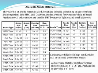
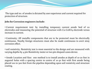
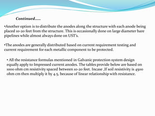
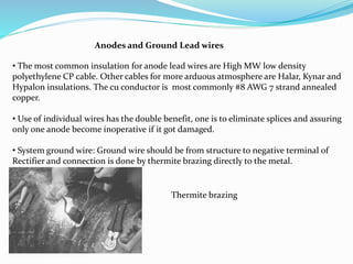
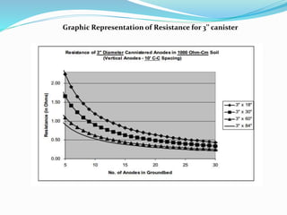
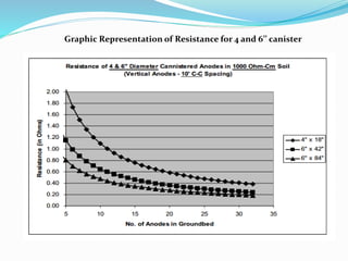
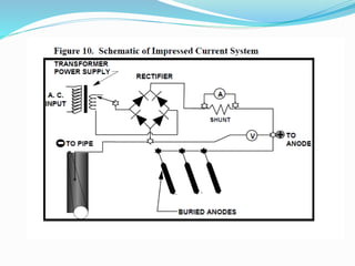


The document discusses impressed current cathodic protection systems which use an external DC power source to provide corrosion protection for large structures like pipelines and storage tanks. It describes the system components including anodes, cables, rectifiers and how they work together. Factors that influence design include current requirements, soil resistivity testing and anode placement. Graphs show representative resistance values for different anode types.


